EP1431481A2 - Schloss - Google Patents
Schloss Download PDFInfo
- Publication number
- EP1431481A2 EP1431481A2 EP03026357A EP03026357A EP1431481A2 EP 1431481 A2 EP1431481 A2 EP 1431481A2 EP 03026357 A EP03026357 A EP 03026357A EP 03026357 A EP03026357 A EP 03026357A EP 1431481 A2 EP1431481 A2 EP 1431481A2
- Authority
- EP
- European Patent Office
- Prior art keywords
- latch
- lock
- bolt
- elements
- auxiliary
- Prior art date
- Legal status (The legal status is an assumption and is not a legal conclusion. Google has not performed a legal analysis and makes no representation as to the accuracy of the status listed.)
- Granted
Links
Images



Classifications
-
- E—FIXED CONSTRUCTIONS
- E05—LOCKS; KEYS; WINDOW OR DOOR FITTINGS; SAFES
- E05B—LOCKS; ACCESSORIES THEREFOR; HANDCUFFS
- E05B63/00—Locks or fastenings with special structural characteristics
- E05B63/18—Locks or fastenings with special structural characteristics with arrangements independent of the locking mechanism for retaining the bolt or latch in the retracted position
- E05B63/20—Locks or fastenings with special structural characteristics with arrangements independent of the locking mechanism for retaining the bolt or latch in the retracted position released automatically when the wing is closed
-
- E—FIXED CONSTRUCTIONS
- E05—LOCKS; KEYS; WINDOW OR DOOR FITTINGS; SAFES
- E05B—LOCKS; ACCESSORIES THEREFOR; HANDCUFFS
- E05B47/00—Operating or controlling locks or other fastening devices by electric or magnetic means
- E05B47/0001—Operating or controlling locks or other fastening devices by electric or magnetic means with electric actuators; Constructional features thereof
- E05B2047/0014—Constructional features of actuators or power transmissions therefor
- E05B2047/0018—Details of actuator transmissions
- E05B2047/002—Geared transmissions
-
- E—FIXED CONSTRUCTIONS
- E05—LOCKS; KEYS; WINDOW OR DOOR FITTINGS; SAFES
- E05B—LOCKS; ACCESSORIES THEREFOR; HANDCUFFS
- E05B47/00—Operating or controlling locks or other fastening devices by electric or magnetic means
- E05B2047/0094—Mechanical aspects of remotely controlled locks
-
- E—FIXED CONSTRUCTIONS
- E05—LOCKS; KEYS; WINDOW OR DOOR FITTINGS; SAFES
- E05B—LOCKS; ACCESSORIES THEREFOR; HANDCUFFS
- E05B47/00—Operating or controlling locks or other fastening devices by electric or magnetic means
- E05B47/0001—Operating or controlling locks or other fastening devices by electric or magnetic means with electric actuators; Constructional features thereof
- E05B47/0012—Operating or controlling locks or other fastening devices by electric or magnetic means with electric actuators; Constructional features thereof with rotary electromotors
-
- E—FIXED CONSTRUCTIONS
- E05—LOCKS; KEYS; WINDOW OR DOOR FITTINGS; SAFES
- E05B—LOCKS; ACCESSORIES THEREFOR; HANDCUFFS
- E05B47/00—Operating or controlling locks or other fastening devices by electric or magnetic means
- E05B47/06—Controlling mechanically-operated bolts by electro-magnetically-operated detents
- E05B47/0676—Controlling mechanically-operated bolts by electro-magnetically-operated detents by disconnecting the handle
-
- E—FIXED CONSTRUCTIONS
- E05—LOCKS; KEYS; WINDOW OR DOOR FITTINGS; SAFES
- E05B—LOCKS; ACCESSORIES THEREFOR; HANDCUFFS
- E05B53/00—Operation or control of locks by mechanical transmissions, e.g. from a distance
- E05B53/003—Operation or control of locks by mechanical transmissions, e.g. from a distance flexible
-
- E—FIXED CONSTRUCTIONS
- E05—LOCKS; KEYS; WINDOW OR DOOR FITTINGS; SAFES
- E05B—LOCKS; ACCESSORIES THEREFOR; HANDCUFFS
- E05B63/00—Locks or fastenings with special structural characteristics
- E05B63/0065—Operating modes; Transformable to different operating modes
-
- E—FIXED CONSTRUCTIONS
- E05—LOCKS; KEYS; WINDOW OR DOOR FITTINGS; SAFES
- E05B—LOCKS; ACCESSORIES THEREFOR; HANDCUFFS
- E05B65/00—Locks or fastenings for special use
- E05B65/10—Locks or fastenings for special use for panic or emergency doors
- E05B65/1086—Locks with panic function, e.g. allowing opening from the inside without a ley even when locked from the outside
Definitions
- the invention relates to a self-locking lock according to the preamble of Claim 1.
- the disadvantage here is that the mortise lock, due to its dimensions, only for Doors with a long lock pocket is suitable, as it has metal doors.
- the lock cannot be inserted into the lock pocket of a wooden door because these doors have shorter but deeper lock pockets.
- Furthermore can when the door is open, by manually actuating the control section, for example by playing Children who triggered the bolt lock, causing the door to fail lets close more. This is particularly disadvantageous if the door with a Door drive is provided or is controlled from a control center.
- DE 197 01 761 C1 shows a self-locking lock with a bolt, a lock latch, an auxiliary latch and a slide plate, in which the bolt and exclude the lock latch spring-loaded and when locked Door and locked position are locked, and in which the bolt with the door open and in the fully retracted position through the auxiliary latch is locked over the slide plate.
- the lock is not universally different Lock pockets can be used. Because the closed position the door is only caught on one side by the lock latch, it can The bolt lock comes against the striking plate and the bolt closes the door not safe. The additional trap widening arranged in the trap the trap part may be susceptible and could jam.
- the invention has for its object to form a lock in one Can be used in the lock pockets of metal doors and wooden doors is secured against accidental release of the bolt, and that a safe one The latch engages in the striking plate.
- Self-locking locks are often used to lock external doors ensure that a building is locked to prevent burglary.
- Locks are also designed as self-locking panic locks Escape and rescue routes are used. Through the panic function by pressing the lever handle the latch and bolt into the lock withdrawn, whereby the previously closed door can be opened immediately.
- Locks are usually made in different versions, because, for example, metal doors have a different lock pocket to hold of the castle have as metal doors. Wooden doors have deep lock pockets with a lower height, in contrast metal doors leave only a small one Installation depth, but a greater overall height.
- the lock according to the invention is dimensioned so that it fits into the lock pockets of metal and Wooden doors fit in equally because of its special construction the smaller size of the lock pockets is executed. This is special Advantage because only one lock is required for different door types.
- a lock works with one arranged on the door frame Striking plate together, which has one or more recesses in which a latch and a latch can intervene.
- the well-known cross traps exist from two immediately adjacent trap elements, which are made of swivel the faceplate of the lock out and into the recess of the Strike plate can intervene.
- the latch elements swivel out of the faceplate into the recess in the striking plate that the latch elements are each on one of the Support the opposite inside of the recess.
- auxiliary latch is provided on such locks, which when closing the door can be operated by the striking plate and the bolt lock release.
- the auxiliary trap can also be played by children, for example operated, which triggers the bolt lock and thus the door can no longer be closed.
- the lock according to the invention therefore has a safety device which does not trigger a bolt lock until the auxiliary latch and at the same time the Trap elements were actuated, and then the trap elements again from the Have reached the swung-out position.
- This process corresponds to that Closing process of the door, the auxiliary latch and the latch elements working together be pivoted with the striking plate.
- the auxiliary latch remains activated and the latch elements engage the recess of the striking plate and get into their swung out Status. Only then will the bolt exclusion be triggered.
- the bolt loaded by a spring is arranged in a slide Led scenery. Only by releasing the sliding movement of the slide the bolt can change its position and the spring over the faceplate be led out of the lock case.
- the slide To release the sliding movement of the slide, on the one hand, the actuation the auxiliary trap required and the actuation of the trap elements.
- the slide also has another lock by a Swing lever on, which only when the latch elements are fully swung out again is released. Only this sequence releases the slide and the spring-loaded latches can rule out, ensuring that the door is closed and the bolt through the latch elements in the recess in Strike plate is centered and can therefore exclude freely. The door will be safe locked.
- the lock can be designed as a purely mechanical, self-locking lock and be equipped with a panic function, the lock of one Side can be unlocked at any time by pressing a button.
- the lock is usually only opened by one Lock cylinder possible because only a door knob is installed instead of a handle to prevent unauthorized access.
- the lock can also be equipped with a split follower, which can be actuated electromagnetically, for example.
- a split follower which can be actuated electromagnetically, for example. This enables to decouple the handle on one side of the lock from the opening mechanism, which can be used to control access to a secure area. This can be done by an access control, whether by a gatekeeper or by an electronic one Access control system such as chip card, code entry or fingerprint.
- the two halves of the handle nut - through triggered the electromagnet - coupled together and the lock can also be operated using the outer handle.
- the state of the castle can be detected via switch elements and a controller or Notification device are supplied.
- the lock can also be designed as a motor lock. It can be an engine Actuate an actuating element via a toothed belt, with several actuating positions what different functions of the lock are conceivable cause. The state of the lock and the actuator is over Switch elements detectable.
- Different day and night positions or permanent open positions are possible, wherein the actuator is required by the motor in the respective Position is brought.
- the position for controlling the motor can be over the switching elements are detected.
- Access to the door quickly can be dispensed with will exclude the bolt.
- the latch elements can be locked effect and take over a door release function. Are the trap elements locked, the door cannot be opened, but is immediately after release whether through an electronic access control system or a gate, accessible because the Can swing in latch elements immediately after release.
- a motor The bolt feed which always takes a certain amount of time, is eliminated, which means that access can be quicker than with conventional motor locks.
- the actuator can be moved to a further position, whereby the Latch is excluded.
- the actuating element that the bolt is pulled back into the lock case. After the door is subsequently closed, the deadbolt can be automatically excluded for a secure locking of the door.
- a self-locking lock 1 with a faceplate 2 for assembly the lock 1 in a lock pocket not shown here Door shown, with a lock case 3, which is in the lock pocket of the door is recorded.
- the lock case 3 is designed in its dimensions so that lock 1 in the lock pockets of metal and wooden doors alike fits. This is of particular advantage because for different Door types only one lock 1 is required. Wooden doors have deep lock pockets with a lower height. In contrast, metal doors leave little Installation depth, but a greater overall height. The castle 1 is through its special construction to the smaller size of the lock pockets.
- the faceplate 2 of the lock 1 shown in plan view in FIG. 2 is interchangeable, making it easy to adapt to different door designs is possible.
- a lock 1 acts with one arranged in the frame Striking plate together, which has one or more recesses 28, in which a latch and a latch 6 can engage.
- the dashed in Fig. 2 Lines sketched recess 28 of the striking plate not shown illustrates the optimal centering of bolt 6.
- the well-known cross latches consist of two immediately adjacent latch elements 4, 5, which can swivel into the plane of the faceplate 2, and swung out Condition in the recess 28 of the striking plate arranged on the door frame intervention.
- the split arrangement of the cross latch, with an upper latch element 4 above and a lower latch element 5 below the bolt 6, allows one Centering the lock 1 relative to the striking plate and thus a secure one Exclude and engage the bolt 6 in the recess 28 of the striking plate.
- the latch elements 4, 5 thus pivot out of the faceplate 2 into the Recess 28 in the striking plate that the latch elements 4, 5 in each case support one of the opposite inner sides of the recess 28.
- a possibly existing inclination of the striking plate opposite the lock 1, for example by warping the door, can be due to the distance between the upper case element 4 and the lower case element 5 nevertheless be centered.
- auxiliary latch 11 is provided on such known locks 1, which is actuated when the door is closed by the striking plate and the bolt lock releases.
- the auxiliary trap 11 could also be used, for example playing children are actuated, which triggers the bolt exclusion and the door can no longer be closed.
- the lock 1 has a drainage protection, which one Bolt exclusion only triggers when the auxiliary latch 11 and at the same time the Trap elements 4, 5 were actuated and then the trap elements 4, 5 again have reached position swung out of faceplate 2.
- This process corresponds the closing process of the door, the auxiliary latch 11 and the latch elements 4, 5 can be pivoted by cooperation with the striking plate.
- the auxiliary latch 11 remains activated, the latch elements 4, 5, however, engage in the recess of the striking plate and enter their swung out state. Only then will the bolt exclusion be triggered.
- the bolt 6 loaded by the spring 15 is arranged in the slide 7 Set 8 guided, as shown in Figures 1 and 3.
- the bolt 6 can change its position, and by the spring 15 beyond the faceplate 2 out of the lock case 3 be performed.
- Farther is the locking bolt arranged on the rocker 21 of the lower latch element 5 9 engages with the latch catch 10.
- the locking pin 9 only gives the slider 7 then free when the latch elements 4, 5 are pivoted out.
- the trap elements 4,5 are operatively connected to each other via the rockers 21 and can only work together be pivoted, as can be seen from Fig.
- the lock 1 can be designed as a purely mechanical, self-locking lock and be equipped with a panic function, the lock 1 by a Side can be unlocked at any time by pressing a button. From the other side, the lock is usually only opened via the Lock cylinder 16 possible because only a door knob is installed instead of a handle becomes.
- a split follower 14 which can be actuated electromagnetically. This makes it possible to press the pusher one Decouple the lock side from the opening mechanism, which gives access in a secured area can be controlled. This can be done through an access control, whether through a gatekeeper or through an electronic access control system, such as chip card, code entry or fingerprint. If justified The two halves of the follower 14 are accessed by the electromagnet triggered - coupled with each other, and the lock 1 can also via the outer pusher. The state of the lock 1 can over Switch elements 19 detected and fed to a controller or signaling device become.
- FIG. 1 Another embodiment of the lock 1 is a motor-operated, which can be seen from Figures 3 to 5.
- a motor 17 can have a toothed belt 18 actuate an actuating element 20.
- the State of the lock 1 and the actuating element 20 is on the Switch elements 19 detectable.
- a different day and night position is conceivable, with the actuating element 20 brought into the required position by the motor 17 , the position for controlling the motor 17 via the switching elements 19 is detected.
- the latch can be dispensed with 6 to rule out, since the latch elements 4, 5 cause a lock and can take over a door release function. If the latch elements 4, 5 are locked, the door cannot be opened, but is immediately after release, whether through an electronic access control system or a gate, accessible because of the trap elements 4, 5 swing in immediately.
- a motorized bolt feed which Always takes a certain amount of time, which makes access faster than can be done with conventional motor locks.
- the bolt 6 excludes and secures the door to prevent burglary. This can be done by a motor Moving the actuating element 20 into a further position, the bolt 6 is excluded via the backdrop 8 in the slide 6. For authorized access is given to the bolt 6 along the backdrop 8 by the actuating element 20 retracted into the lock case 3. After the following When the door is closed, the bolt is automatically excluded for securely locking the door.
Landscapes
- Engineering & Computer Science (AREA)
- Structural Engineering (AREA)
- Lock And Its Accessories (AREA)
- Pharmaceuticals Containing Other Organic And Inorganic Compounds (AREA)
- Hydrogenated Pyridines (AREA)
- Vehicle Step Arrangements And Article Storage (AREA)
Abstract
Description
- Fig. 1
- ein Schloss mit geteilter Kreuzfalle und Ablaufsicherung, geöffnet in der Seitenansicht;
- Fig. 2
- das Schloss nach Fig. 1, in der Ansicht auf die Stulp;
- Fig. 3
- das Schloss nach Fig. 1, als Motorschloss ausgebildet.
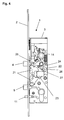
- Fig. 4
- das Schloss nach Fig. 3, in teilweise demontiertem Zustand, mit der Darstellung der Blockierung des Riegels bei ausgeschwenkten Fallenelementen.
- Fig. 5
- das Schloss nach Fig. 4, jedoch mit eingeschwenkten Fallenelementen.
- 1
- Schloss
- 2
- Stulp
- 3
- Schlosskasten
- 4
- oberes Fallenelement
- 5
- unteres Fallenelement
- 6
- Riegel
- 7
- Schieber
- 8
- Kulisse
- 9
- Sperrbolzen
- 10
- Fallenraste
- 11
- Hilfsfalle
- 12
- Sperre
- 13
- Hilfsfallenraste
- 14
- Drückernuss
- 15
- Feder
- 16
- Schließzylinder
- 17
- Motor
- 18
- Zahnriemen
- 19
- Schalterelemente
- 20
- Betätigungselement
- 21
- Wippe
- 22
- Rückholelement
- 23
- Fallensperre
- 24
- Übersetzer
- 25
- Schieberbolzen
- 26
- Rückhaltebolzen
- 27
- Rückhaltenocken
- 28
- Aussparung des Schließblechs
Claims (9)
- Schloss, mit einem Schlosskasten, einer Stulp, mit einem im Schlosskasten angeordneten, federbeaufschlagten Riegel, einer Hilfsfalle und einer Kreuzfalle, wobei die Kreuzfalle ein oberes und ein unteres Fallenelement aufweist, mit einem mit einer Kulisse und mit Rasten versehenen Schieber, wobei Sperren zur Steuerung des Riegelausschlusses in die Rasten eingreifen, mit einer über einen Türdrücker betätigbaren Drückernuss zur Betätigung des Schlosses,
dadurch gekennzeichnet, dass das obere Fallenelement (4) der Kreuzfalle oberhalb des Riegels (6) und das untere Fallenelement (5) unterhalb des Riegels (6) angeordnet ist, und diese mit der Hilfsfalle (11) derart wirkverbunden sind, dass der Riegelausschluss nur dann ausgelöst wird, wenn nach gleichzeitiger Betätigung der Fallenelemente (5, 6) und der Hilfsfalle (11) die Fallenelemente (5, 6) der Kreuzfalle in ihre über die Stulp (2) aus dem Schlosskasten (3) ausgeschwenkte Stellung gelangt sind, wobei die Hilfsfalle (11) betätigt bleibt. - Schloss nach Anspruch 1,
dadurch gekennzeichnet, dass das obere Fallenelement (4) und das untere Fallenelement (5) bei geschlossenem Flügel und unbetätigter Drückernuss (14) versteift sind. - Schloss nach Anspruch 2,
dadurch gekennzeichnet, dass die versteiften Fallenelemente (4, 5) das Schloss (1) gegenüber einem Schließblech zentrieren und der Riegel (6) frei in eine Aussparung (28) des Schließblechs ausschließen kann. - Schloss nach Anspruch 1,
dadurch gekennzeichnet, dass der Riegelausschluss des Riegels (6) durch Führung des Riegels (6) in einer Kulisse (8) des Schiebers (7) gesteuert ist. - Schloss nach Anspruch 1,
dadurch gekennzeichnet, dass die Drückernuss (14) eine geteilte Drückernuss ist und elektromagnetisch koppelbar ist. - Schloss nach Anspruch 1,
dadurch gekennzeichnet, dass das Schloss (1) ein Betätigungselement (20) aufweist, womit die Fallenelemente (4, 5) und der Riegel (6) betätigbar sind. - Schloss nach Anspruch 6,
dadurch gekennzeichnet, dass das Betätigungselement (20) durch einen Motor (17) betätigt wird. - Schloss nach Anspruch 6,
dadurch gekennzeichnet, dass die Kreuzfalle eine Türöffnerfunktion erfüllt, wobei das Betätigungselement (20) den Schieber (7) in eine Zwischenstellung führt. - Schloss nach Anspruch 1,
dadurch gekennzeichnet,dassdasSchloss(1)zurSteuerung und Zustandsrückmeldung Schalterelemente (19) aufweist.
Applications Claiming Priority (2)
| Application Number | Priority Date | Filing Date | Title |
|---|---|---|---|
| DE2002161129 DE10261129B4 (de) | 2002-12-20 | 2002-12-20 | Selbstverriegelndes Schloss |
| DE10261129 | 2002-12-20 |
Publications (3)
| Publication Number | Publication Date |
|---|---|
| EP1431481A2 true EP1431481A2 (de) | 2004-06-23 |
| EP1431481A3 EP1431481A3 (de) | 2008-04-02 |
| EP1431481B1 EP1431481B1 (de) | 2010-06-02 |
Family
ID=32336607
Family Applications (1)
| Application Number | Title | Priority Date | Filing Date |
|---|---|---|---|
| EP03026357A Expired - Lifetime EP1431481B1 (de) | 2002-12-20 | 2003-11-18 | Schloss |
Country Status (6)
| Country | Link |
|---|---|
| EP (1) | EP1431481B1 (de) |
| AT (1) | ATE470036T1 (de) |
| DE (2) | DE10261129B4 (de) |
| DK (1) | DK1431481T3 (de) |
| ES (1) | ES2344688T3 (de) |
| PT (1) | PT1431481E (de) |
Cited By (13)
| Publication number | Priority date | Publication date | Assignee | Title |
|---|---|---|---|---|
| WO2006070025A1 (es) * | 2004-12-23 | 2006-07-06 | Talleres De Escoriaza, S.A. | Una cerradura de embutir con salida automatica de palanca |
| WO2006070062A1 (en) * | 2004-12-31 | 2006-07-06 | Roca Finland Oy | Lock |
| EP1777361A2 (de) | 2005-10-24 | 2007-04-25 | Sitech-Sicherheitstechnik GmbH | Schloss, insbesondere Einstemmschloss |
| US7526933B2 (en) | 2006-10-18 | 2009-05-05 | Master Lock Company Llc | Multipoint door lock |
| EP2151536A3 (de) * | 2008-08-06 | 2010-09-08 | ISEO SERRATURE S.p.A. | Schloss mit mehreren automatischen Schließpunkten |
| EP1990487A3 (de) * | 2007-05-11 | 2011-03-09 | Grundmann Beschlagtechnik GmbH | Türschloss |
| CN102191890A (zh) * | 2010-03-04 | 2011-09-21 | 模帝乐技术有限公司 | 具有可选择的功能的插锁 |
| EP3111964A1 (de) * | 2015-07-03 | 2017-01-04 | Ermis Medizintechnik e.K. | Verschlussmechanismus und siebkorb mit einem deckel, der den verschlussmechanismus umfasst |
| EP3135842A1 (de) * | 2015-08-28 | 2017-03-01 | YKK AP Inc. | Schlossvorrichtung mit öffnungsunterstützungsmechanismus und schiebetür mit schlossvorrichtung mit öffnungsunterstützungsmechanismus |
| EP2543802A3 (de) * | 2011-07-06 | 2017-06-14 | MACO Technologie GmbH | Schloss |
| EP3619382B1 (de) | 2017-05-04 | 2021-07-07 | ERA Home Security Limited | Sperranordnung |
| EP3299552B1 (de) | 2016-09-26 | 2024-07-31 | ASSA ABLOY (Schweiz) AG | Modulares schloss |
| US12428874B2 (en) | 2021-12-17 | 2025-09-30 | Assa Abloy Americas Residential Inc. | Electronic lock with mortise insert |
Families Citing this family (12)
| Publication number | Priority date | Publication date | Assignee | Title |
|---|---|---|---|---|
| RU2334070C2 (ru) * | 2004-12-22 | 2008-09-20 | Гезе Гмбх | Замок |
| DE502006001129D1 (de) | 2006-02-02 | 2008-08-28 | Geze Gmbh | Schloss |
| DE102008016698B4 (de) * | 2008-03-31 | 2021-03-04 | Dormakaba Deutschland Gmbh | Schloss mit einem Selektorelement zur Umstellung der Funktionseigenschaften des Schlosses |
| DE102010032639A1 (de) | 2010-07-16 | 2012-01-19 | Hörmann KG Eckelhausen | Tür mit manuell betätigbarem Drücker |
| DE102012101658A1 (de) | 2012-02-29 | 2013-08-29 | Dorma Gmbh + Co. Kg | Schloss |
| DE102014104129A1 (de) * | 2014-03-25 | 2015-10-01 | Assa Abloy Nederland B.V. | Schloss für Tür oder Fenster |
| JP6534805B2 (ja) * | 2014-11-05 | 2019-06-26 | 不二サッシ株式会社 | ハンドルの誤動作防止装置および開き窓 |
| DE102015210948A1 (de) * | 2015-06-15 | 2016-12-15 | Geze Gmbh | Schloss |
| DE102016207937C5 (de) * | 2016-05-09 | 2023-12-07 | Geze Gmbh | Schloss mit mehreren Verriegelungselementen |
| DE102016207939B4 (de) | 2016-05-09 | 2020-05-28 | Geze Gmbh | Schloss für einen schwenkbaren Flügel |
| DE102016207938A1 (de) | 2016-05-09 | 2017-11-09 | Geze Gmbh | Schloss für einen schwenkbaren Flügel |
| DE102017208731A1 (de) | 2017-05-23 | 2018-11-29 | Geze Gmbh | Druckernussanordnung für einen beweglichen Flügel |
Family Cites Families (5)
| Publication number | Priority date | Publication date | Assignee | Title |
|---|---|---|---|---|
| DE8704036U1 (de) * | 1987-03-18 | 1987-07-02 | BKS GmbH, 5620 Velbert | Türschloß mit Verriegelungselement und Hilfsfalle |
| DE4337969A1 (de) * | 1993-10-15 | 1995-04-20 | Theodor Krachten | Selbstverriegelndes Sicherheitstürschloß |
| US6217087B1 (en) * | 1994-12-07 | 2001-04-17 | Mark Weston Fuller | Lock mechanism |
| DE19626752C2 (de) * | 1996-07-03 | 1998-07-30 | Dorma Gmbh & Co Kg | Selbstverriegelndes Einsteckschloß |
| DE19701761C1 (de) * | 1997-01-20 | 1998-04-16 | Fuss Fritz Gmbh & Co | Selbstverriegelndes Schloß |
-
2002
- 2002-12-20 DE DE2002161129 patent/DE10261129B4/de not_active Expired - Lifetime
-
2003
- 2003-11-18 EP EP03026357A patent/EP1431481B1/de not_active Expired - Lifetime
- 2003-11-18 AT AT03026357T patent/ATE470036T1/de active
- 2003-11-18 DE DE50312760T patent/DE50312760D1/de not_active Expired - Lifetime
- 2003-11-18 ES ES03026357T patent/ES2344688T3/es not_active Expired - Lifetime
- 2003-11-18 DK DK03026357.8T patent/DK1431481T3/da active
- 2003-11-18 PT PT03026357T patent/PT1431481E/pt unknown
Cited By (17)
| Publication number | Priority date | Publication date | Assignee | Title |
|---|---|---|---|---|
| WO2006070025A1 (es) * | 2004-12-23 | 2006-07-06 | Talleres De Escoriaza, S.A. | Una cerradura de embutir con salida automatica de palanca |
| WO2006070062A1 (en) * | 2004-12-31 | 2006-07-06 | Roca Finland Oy | Lock |
| EP1777361A2 (de) | 2005-10-24 | 2007-04-25 | Sitech-Sicherheitstechnik GmbH | Schloss, insbesondere Einstemmschloss |
| EP1777361A3 (de) * | 2005-10-24 | 2008-10-01 | Sitech-Sicherheitstechnik GmbH | Schloss, insbesondere Einstemmschloss |
| US7526933B2 (en) | 2006-10-18 | 2009-05-05 | Master Lock Company Llc | Multipoint door lock |
| EP1990487A3 (de) * | 2007-05-11 | 2011-03-09 | Grundmann Beschlagtechnik GmbH | Türschloss |
| EP2151536A3 (de) * | 2008-08-06 | 2010-09-08 | ISEO SERRATURE S.p.A. | Schloss mit mehreren automatischen Schließpunkten |
| WO2011109573A3 (en) * | 2010-03-04 | 2012-04-26 | Mul-T-Lock Technologies Ltd. | Mortise lock with selectable functions |
| CN102191890A (zh) * | 2010-03-04 | 2011-09-21 | 模帝乐技术有限公司 | 具有可选择的功能的插锁 |
| CN102191890B (zh) * | 2010-03-04 | 2015-09-23 | 模帝乐技术有限公司 | 具有可选择的功能的插锁 |
| EP2543802A3 (de) * | 2011-07-06 | 2017-06-14 | MACO Technologie GmbH | Schloss |
| EP2543802B1 (de) | 2011-07-06 | 2018-09-12 | MACO Technologie GmbH | Schloss |
| EP3111964A1 (de) * | 2015-07-03 | 2017-01-04 | Ermis Medizintechnik e.K. | Verschlussmechanismus und siebkorb mit einem deckel, der den verschlussmechanismus umfasst |
| EP3135842A1 (de) * | 2015-08-28 | 2017-03-01 | YKK AP Inc. | Schlossvorrichtung mit öffnungsunterstützungsmechanismus und schiebetür mit schlossvorrichtung mit öffnungsunterstützungsmechanismus |
| EP3299552B1 (de) | 2016-09-26 | 2024-07-31 | ASSA ABLOY (Schweiz) AG | Modulares schloss |
| EP3619382B1 (de) | 2017-05-04 | 2021-07-07 | ERA Home Security Limited | Sperranordnung |
| US12428874B2 (en) | 2021-12-17 | 2025-09-30 | Assa Abloy Americas Residential Inc. | Electronic lock with mortise insert |
Also Published As
| Publication number | Publication date |
|---|---|
| ATE470036T1 (de) | 2010-06-15 |
| EP1431481B1 (de) | 2010-06-02 |
| DK1431481T3 (da) | 2010-10-04 |
| DE10261129A1 (de) | 2004-07-01 |
| ES2344688T3 (es) | 2010-09-03 |
| DE10261129B4 (de) | 2005-01-13 |
| EP1431481A3 (de) | 2008-04-02 |
| DE50312760D1 (de) | 2010-07-15 |
| PT1431481E (pt) | 2010-06-21 |
Similar Documents
| Publication | Publication Date | Title |
|---|---|---|
| EP1431481B1 (de) | Schloss | |
| EP3832055B1 (de) | Verriegelungseinheit für eine schliessanlage einer tür | |
| DE102006059565B4 (de) | Schließanlage für Türen, Fenster oder dergleichen, insbesondere Treibstangenschloss mit Panikfunktion und Mehrpunktverriegelung | |
| EP2543802B1 (de) | Schloss | |
| DE4337969A1 (de) | Selbstverriegelndes Sicherheitstürschloß | |
| EP0816603B1 (de) | Selbstverriegelndes Panikschloss | |
| DE3801441C2 (de) | ||
| EP0816602B1 (de) | Selbstverriegelndes Einsteckschloss | |
| DE2433322A1 (de) | Mehrfallen-panikverschluss | |
| DE19546467C1 (de) | Sicherheitsschloß | |
| DE19845515C2 (de) | Schließvorrichtung für ein Schloß | |
| EP3165696B1 (de) | Schloss mit kuppelbarer schlossnuss | |
| EP0779402A1 (de) | Sicherheitsschloss | |
| AT9709U1 (de) | Türschloss | |
| DE19613638A1 (de) | Schloß | |
| DE19546466C1 (de) | Sicherheitsschloß | |
| DE3931101A1 (de) | Automatisch verriegelndes schloss | |
| DE10125915A1 (de) | Fehlbedienungssicheres Schiebeflügel- oder Schwenkflügelschloss | |
| EP1816289B1 (de) | Schloss | |
| EP3208407B1 (de) | Schloss mit einer sicherheitsvorrichtung | |
| EP3406828A1 (de) | Schloss für einen flügel | |
| EP0439478B1 (de) | Selbsttätiges schloss | |
| EP1617018A2 (de) | Elektromechanisches Türschloss | |
| AT407066B (de) | Türfängerverschluss | |
| EP1936076B1 (de) | Selbstverriegelndes Panikschloss |
Legal Events
| Date | Code | Title | Description |
|---|---|---|---|
| PUAI | Public reference made under article 153(3) epc to a published international application that has entered the european phase |
Free format text: ORIGINAL CODE: 0009012 |
|
| AK | Designated contracting states |
Kind code of ref document: A2 Designated state(s): AT BE BG CH CY CZ DE DK EE ES FI FR GB GR HU IE IT LI LU MC NL PT RO SE SI SK TR |
|
| AX | Request for extension of the european patent |
Extension state: AL LT LV MK |
|
| PUAL | Search report despatched |
Free format text: ORIGINAL CODE: 0009013 |
|
| AK | Designated contracting states |
Kind code of ref document: A3 Designated state(s): AT BE BG CH CY CZ DE DK EE ES FI FR GB GR HU IE IT LI LU MC NL PT RO SE SI SK TR |
|
| AX | Request for extension of the european patent |
Extension state: AL LT LV MK |
|
| 17P | Request for examination filed |
Effective date: 20080911 |
|
| AKX | Designation fees paid |
Designated state(s): AT BE BG CH CY CZ DE DK EE ES FI FR GB GR HU IE IT LI LU MC NL PT RO SE SI SK TR |
|
| GRAP | Despatch of communication of intention to grant a patent |
Free format text: ORIGINAL CODE: EPIDOSNIGR1 |
|
| GRAS | Grant fee paid |
Free format text: ORIGINAL CODE: EPIDOSNIGR3 |
|
| GRAA | (expected) grant |
Free format text: ORIGINAL CODE: 0009210 |
|
| AK | Designated contracting states |
Kind code of ref document: B1 Designated state(s): AT BE BG CH CY CZ DE DK EE ES FI FR GB GR HU IE IT LI LU MC NL PT RO SE SI SK TR |
|
| REG | Reference to a national code |
Ref country code: GB Ref legal event code: FG4D Free format text: NOT ENGLISH |
|
| REG | Reference to a national code |
Ref country code: CH Ref legal event code: EP |
|
| REG | Reference to a national code |
Ref country code: PT Ref legal event code: SC4A Free format text: AVAILABILITY OF NATIONAL TRANSLATION Effective date: 20100614 |
|
| REG | Reference to a national code |
Ref country code: IE Ref legal event code: FG4D Free format text: LANGUAGE OF EP DOCUMENT: GERMAN |
|
| REF | Corresponds to: |
Ref document number: 50312760 Country of ref document: DE Date of ref document: 20100715 Kind code of ref document: P |
|
| REG | Reference to a national code |
Ref country code: NL Ref legal event code: T3 |
|
| REG | Reference to a national code |
Ref country code: ES Ref legal event code: FG2A Ref document number: 2344688 Country of ref document: ES Kind code of ref document: T3 |
|
| REG | Reference to a national code |
Ref country code: SE Ref legal event code: TRGR |
|
| REG | Reference to a national code |
Ref country code: DK Ref legal event code: T3 |
|
| PG25 | Lapsed in a contracting state [announced via postgrant information from national office to epo] |
Ref country code: SI Free format text: LAPSE BECAUSE OF FAILURE TO SUBMIT A TRANSLATION OF THE DESCRIPTION OR TO PAY THE FEE WITHIN THE PRESCRIBED TIME-LIMIT Effective date: 20100602 |
|
| PG25 | Lapsed in a contracting state [announced via postgrant information from national office to epo] |
Ref country code: GR Free format text: LAPSE BECAUSE OF FAILURE TO SUBMIT A TRANSLATION OF THE DESCRIPTION OR TO PAY THE FEE WITHIN THE PRESCRIBED TIME-LIMIT Effective date: 20100903 Ref country code: CY Free format text: LAPSE BECAUSE OF FAILURE TO SUBMIT A TRANSLATION OF THE DESCRIPTION OR TO PAY THE FEE WITHIN THE PRESCRIBED TIME-LIMIT Effective date: 20100602 |
|
| REG | Reference to a national code |
Ref country code: IE Ref legal event code: FD4D |
|
| PG25 | Lapsed in a contracting state [announced via postgrant information from national office to epo] |
Ref country code: IE Free format text: LAPSE BECAUSE OF FAILURE TO SUBMIT A TRANSLATION OF THE DESCRIPTION OR TO PAY THE FEE WITHIN THE PRESCRIBED TIME-LIMIT Effective date: 20100602 |
|
| PG25 | Lapsed in a contracting state [announced via postgrant information from national office to epo] |
Ref country code: CZ Free format text: LAPSE BECAUSE OF FAILURE TO SUBMIT A TRANSLATION OF THE DESCRIPTION OR TO PAY THE FEE WITHIN THE PRESCRIBED TIME-LIMIT Effective date: 20100602 Ref country code: SK Free format text: LAPSE BECAUSE OF FAILURE TO SUBMIT A TRANSLATION OF THE DESCRIPTION OR TO PAY THE FEE WITHIN THE PRESCRIBED TIME-LIMIT Effective date: 20100602 Ref country code: RO Free format text: LAPSE BECAUSE OF FAILURE TO SUBMIT A TRANSLATION OF THE DESCRIPTION OR TO PAY THE FEE WITHIN THE PRESCRIBED TIME-LIMIT Effective date: 20100602 |
|
| PLBE | No opposition filed within time limit |
Free format text: ORIGINAL CODE: 0009261 |
|
| STAA | Information on the status of an ep patent application or granted ep patent |
Free format text: STATUS: NO OPPOSITION FILED WITHIN TIME LIMIT |
|
| 26N | No opposition filed |
Effective date: 20110303 |
|
| REG | Reference to a national code |
Ref country code: DE Ref legal event code: R097 Ref document number: 50312760 Country of ref document: DE Effective date: 20110302 |
|
| PG25 | Lapsed in a contracting state [announced via postgrant information from national office to epo] |
Ref country code: MC Free format text: LAPSE BECAUSE OF NON-PAYMENT OF DUE FEES Effective date: 20101130 |
|
| REG | Reference to a national code |
Ref country code: CH Ref legal event code: PUE Owner name: MSL SCHLOSS- UND BESCHLAEGEFABRIK AG Free format text: GEZE GMBH#REINHOLD-VOESTER-STRASSE 21-29#71229 LEONBERG (DE) -TRANSFER TO- MSL SCHLOSS- UND BESCHLAEGEFABRIK AG#LAUFENSTRASSE 172#4245 KLEINLUETZEL (CH) Ref country code: CH Ref legal event code: NV Representative=s name: KUNO SCHWANDER |
|
| PG25 | Lapsed in a contracting state [announced via postgrant information from national office to epo] |
Ref country code: HU Free format text: LAPSE BECAUSE OF FAILURE TO SUBMIT A TRANSLATION OF THE DESCRIPTION OR TO PAY THE FEE WITHIN THE PRESCRIBED TIME-LIMIT Effective date: 20101203 Ref country code: BG Free format text: LAPSE BECAUSE OF FAILURE TO SUBMIT A TRANSLATION OF THE DESCRIPTION OR TO PAY THE FEE WITHIN THE PRESCRIBED TIME-LIMIT Effective date: 20100602 |
|
| PG25 | Lapsed in a contracting state [announced via postgrant information from national office to epo] |
Ref country code: BG Free format text: LAPSE BECAUSE OF FAILURE TO SUBMIT A TRANSLATION OF THE DESCRIPTION OR TO PAY THE FEE WITHIN THE PRESCRIBED TIME-LIMIT Effective date: 20100902 |
|
| REG | Reference to a national code |
Ref country code: FR Ref legal event code: PLFP Year of fee payment: 13 |
|
| PGFP | Annual fee paid to national office [announced via postgrant information from national office to epo] |
Ref country code: TR Payment date: 20151027 Year of fee payment: 13 |
|
| PGFP | Annual fee paid to national office [announced via postgrant information from national office to epo] |
Ref country code: PT Payment date: 20151117 Year of fee payment: 13 |
|
| REG | Reference to a national code |
Ref country code: FR Ref legal event code: PLFP Year of fee payment: 14 |
|
| PG25 | Lapsed in a contracting state [announced via postgrant information from national office to epo] |
Ref country code: PT Free format text: LAPSE BECAUSE OF NON-PAYMENT OF DUE FEES Effective date: 20170518 |
|
| REG | Reference to a national code |
Ref country code: FR Ref legal event code: PLFP Year of fee payment: 15 |
|
| PGFP | Annual fee paid to national office [announced via postgrant information from national office to epo] |
Ref country code: NL Payment date: 20201125 Year of fee payment: 18 |
|
| PGFP | Annual fee paid to national office [announced via postgrant information from national office to epo] |
Ref country code: IT Payment date: 20201124 Year of fee payment: 18 Ref country code: SE Payment date: 20201125 Year of fee payment: 18 Ref country code: EE Payment date: 20201116 Year of fee payment: 18 Ref country code: FI Payment date: 20201119 Year of fee payment: 18 Ref country code: DK Payment date: 20201123 Year of fee payment: 18 Ref country code: LU Payment date: 20201118 Year of fee payment: 18 Ref country code: FR Payment date: 20201120 Year of fee payment: 18 Ref country code: AT Payment date: 20201119 Year of fee payment: 18 Ref country code: GB Payment date: 20201120 Year of fee payment: 18 |
|
| PGFP | Annual fee paid to national office [announced via postgrant information from national office to epo] |
Ref country code: BE Payment date: 20201125 Year of fee payment: 18 |
|
| PGFP | Annual fee paid to national office [announced via postgrant information from national office to epo] |
Ref country code: ES Payment date: 20210122 Year of fee payment: 18 |
|
| REG | Reference to a national code |
Ref country code: EE Ref legal event code: MM4A Ref document number: E004600 Country of ref document: EE Effective date: 20211130 |
|
| REG | Reference to a national code |
Ref country code: DK Ref legal event code: EBP Effective date: 20211130 |
|
| PG25 | Lapsed in a contracting state [announced via postgrant information from national office to epo] |
Ref country code: TR Free format text: LAPSE BECAUSE OF NON-PAYMENT OF DUE FEES Effective date: 20161118 |
|
| REG | Reference to a national code |
Ref country code: FI Ref legal event code: MAE |
|
| REG | Reference to a national code |
Ref country code: NL Ref legal event code: MM Effective date: 20211201 |
|
| REG | Reference to a national code |
Ref country code: AT Ref legal event code: MM01 Ref document number: 470036 Country of ref document: AT Kind code of ref document: T Effective date: 20211118 |
|
| GBPC | Gb: european patent ceased through non-payment of renewal fee |
Effective date: 20211118 |
|
| PG25 | Lapsed in a contracting state [announced via postgrant information from national office to epo] |
Ref country code: SE Free format text: LAPSE BECAUSE OF NON-PAYMENT OF DUE FEES Effective date: 20211119 Ref country code: LU Free format text: LAPSE BECAUSE OF NON-PAYMENT OF DUE FEES Effective date: 20211118 Ref country code: EE Free format text: LAPSE BECAUSE OF NON-PAYMENT OF DUE FEES Effective date: 20211130 Ref country code: BE Free format text: LAPSE BECAUSE OF NON-PAYMENT OF DUE FEES Effective date: 20211130 |
|
| REG | Reference to a national code |
Ref country code: BE Ref legal event code: MM Effective date: 20211130 |
|
| PG25 | Lapsed in a contracting state [announced via postgrant information from national office to epo] |
Ref country code: FI Free format text: LAPSE BECAUSE OF NON-PAYMENT OF DUE FEES Effective date: 20211118 Ref country code: AT Free format text: LAPSE BECAUSE OF NON-PAYMENT OF DUE FEES Effective date: 20211118 |
|
| PG25 | Lapsed in a contracting state [announced via postgrant information from national office to epo] |
Ref country code: NL Free format text: LAPSE BECAUSE OF NON-PAYMENT OF DUE FEES Effective date: 20211201 |
|
| PG25 | Lapsed in a contracting state [announced via postgrant information from national office to epo] |
Ref country code: GB Free format text: LAPSE BECAUSE OF NON-PAYMENT OF DUE FEES Effective date: 20211118 Ref country code: DK Free format text: LAPSE BECAUSE OF NON-PAYMENT OF DUE FEES Effective date: 20211130 |
|
| PG25 | Lapsed in a contracting state [announced via postgrant information from national office to epo] |
Ref country code: FR Free format text: LAPSE BECAUSE OF NON-PAYMENT OF DUE FEES Effective date: 20211130 |
|
| PG25 | Lapsed in a contracting state [announced via postgrant information from national office to epo] |
Ref country code: IT Free format text: LAPSE BECAUSE OF NON-PAYMENT OF DUE FEES Effective date: 20211118 |
|
| PGFP | Annual fee paid to national office [announced via postgrant information from national office to epo] |
Ref country code: DE Payment date: 20221130 Year of fee payment: 20 |
|
| REG | Reference to a national code |
Ref country code: ES Ref legal event code: FD2A Effective date: 20230210 |
|
| PGFP | Annual fee paid to national office [announced via postgrant information from national office to epo] |
Ref country code: CH Payment date: 20221201 Year of fee payment: 20 |
|
| PG25 | Lapsed in a contracting state [announced via postgrant information from national office to epo] |
Ref country code: ES Free format text: LAPSE BECAUSE OF NON-PAYMENT OF DUE FEES Effective date: 20211119 |
|
| P01 | Opt-out of the competence of the unified patent court (upc) registered |
Effective date: 20230510 |
|
| REG | Reference to a national code |
Ref country code: DE Ref legal event code: R071 Ref document number: 50312760 Country of ref document: DE |
|
| REG | Reference to a national code |
Ref country code: CH Ref legal event code: PL |