EP1431455A1 - Bahnbehandlungsvorrichtung - Google Patents
Bahnbehandlungsvorrichtung Download PDFInfo
- Publication number
- EP1431455A1 EP1431455A1 EP03027127A EP03027127A EP1431455A1 EP 1431455 A1 EP1431455 A1 EP 1431455A1 EP 03027127 A EP03027127 A EP 03027127A EP 03027127 A EP03027127 A EP 03027127A EP 1431455 A1 EP1431455 A1 EP 1431455A1
- Authority
- EP
- European Patent Office
- Prior art keywords
- cable
- web
- arrangement
- rope
- path
- Prior art date
- Legal status (The legal status is an assumption and is not a legal conclusion. Google has not performed a legal analysis and makes no representation as to the accuracy of the status listed.)
- Granted
Links
- 238000003780 insertion Methods 0.000 claims description 8
- 230000037431 insertion Effects 0.000 claims description 8
- 238000012546 transfer Methods 0.000 claims description 2
- 238000012423 maintenance Methods 0.000 abstract 2
- 230000000694 effects Effects 0.000 description 3
- 230000005484 gravity Effects 0.000 description 3
- 230000037361 pathway Effects 0.000 description 3
- 239000000969 carrier Substances 0.000 description 2
- 238000004519 manufacturing process Methods 0.000 description 2
- 239000000463 material Substances 0.000 description 2
- 238000012545 processing Methods 0.000 description 2
- 239000011248 coating agent Substances 0.000 description 1
- 238000000576 coating method Methods 0.000 description 1
- 238000005520 cutting process Methods 0.000 description 1
- 238000013461 design Methods 0.000 description 1
- 238000006073 displacement reaction Methods 0.000 description 1
- 238000001035 drying Methods 0.000 description 1
- 238000003754 machining Methods 0.000 description 1
- 238000000034 method Methods 0.000 description 1
- 238000005096 rolling process Methods 0.000 description 1
- 238000003860 storage Methods 0.000 description 1
- 238000004804 winding Methods 0.000 description 1
Images



Classifications
-
- D—TEXTILES; PAPER
- D21—PAPER-MAKING; PRODUCTION OF CELLULOSE
- D21G—CALENDERS; ACCESSORIES FOR PAPER-MAKING MACHINES
- D21G9/00—Other accessories for paper-making machines
- D21G9/0063—Devices for threading a web tail through a paper-making machine
- D21G9/0072—Devices for threading a web tail through a paper-making machine using at least one rope
-
- D—TEXTILES; PAPER
- D21—PAPER-MAKING; PRODUCTION OF CELLULOSE
- D21G—CALENDERS; ACCESSORIES FOR PAPER-MAKING MACHINES
- D21G1/00—Calenders; Smoothing apparatus
Definitions
- the invention relates to a web treatment device with a first web insertion device that runs along a first path and a first rope arrangement which is at the beginning of the first path forms a first rope shear, and a second Web insertion device running along a second Path path runs and has a second rope arrangement, the second at the beginning of the second path Rope scissors forms.
- the invention is based on the treatment of a Paper web described. But it is the same Way also applicable to other material webs.
- a paper web producer sometimes wants different ones Can produce products for which one share part of a production line would like, but part of the production line must for a paper web to be traversed while for a different type of paper web or not on others would have to be run through.
- a paper web either so that it runs through a calender, or in other ways to bypass the calender. In practice, this was implemented in such a way that both at the right end (related to the axial direction of the Rolling) the calender a rope arrangement is arranged as well as at the left end.
- the invention has for its object in the leadership a path through the treatment device to have greater flexibility.
- This task is the treatment device type mentioned solved in that both rope arrangements on the same side of the web treatment device are arranged and each rope shear portable is trained.
- Each cable shear is preferably from a takeover position movable into a waiting position, the takeover positions are the same for both rope cutters and a rope cutter is in the waiting position, while the other rope cutter is in the takeover position located.
- the takeover position is the position the rope scissors, on which they receive the incoming paper web, fed from a previous machining section will capture.
- the waiting position is one Position in which the rope cutter is far enough from the incoming one Paper web is removed, so there is no danger there is that the paper web accidentally into the Rope scissors being pulled in.
- the positions are against each other locked, i.e. there can only be one at a time Rope scissors are in the takeover position.
- the other Cable shears are automatically removed from the takeover position moved out.
- the treatment device can are operated with great reliability that the train is either on the first train path or on the second path through the treatment device is passed through. At this point it should be noted be that for the purposes of this explanation passing through the treatment device can also mean that the web on the treatment device is driven past, the treatment device so one way or the other happens.
- the cable shears are preferably on a common one Carriers are fixed, the carrier being displaceable.
- the carrier preferably has a positioning drive on.
- the positioning drive ensures that the Takeover position with a specified accuracy can be achieved. It also makes it easier automatic operation of the treatment device.
- the two path paths preferably point at least a common section, and the rope arrangements are transverse to the web running direction in this section arranged side by side. So the rope arrangements are adjacent to each other in this section. So that carries one takes into account the fact that in one traveled section also a common train path must be set up.
- the cross to the web running direction inner cable arrangement at least in part of the section can be moved out of an area which is transverse to the web running direction next to the Section is arranged.
- the rope arrangement can cause lateral displacement disrupt the web if after a successful one Perform the web with the external rope arrangement cut to width and laterally offset to to be introduced into the treatment device. You simply avoid this problem by that the rope arrangement where it bothers out the path of movement of the train.
- a support element arrangement preferably engages under the liftable rope arrangement and is at least that Height of the support element arrangement can be raised. So that exists also no danger that the web with the support element arrangement collided. It is raised far enough to get out of the range of motion of the web respectively to come out of the strip of the web.
- the support element arrangement is cylindrical Has support elements. Through the round The corresponding cable arrangement becomes the surface of the supporting elements spared, i.e. there is no danger that a notch effect on the cable arrangement due to the supporting elements is spent, causing damage in the medium term could lead.
- the support elements are preferably rotatably mounted.
- the rotatable bearing did not measure that way be stable so that the rope arrangement in operation, i.e. at full filling speed.
- the rope arrangement that is lifted is usually at rest, because only the other rope arrangement is in operation. It is due to the rotatable mounting of the support elements but possible to accommodate small changes in length that may arise when lifting the cable assembly can.
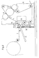
- the paper web 2 is passed through nips 6, 7 which are formed between rollers 8, 9, 10.
- the rollers 8-10 are stored in a stand 11 of the calender 1.
- To guide the paper web 2 along the first path 4 several guide rollers 12-18 are provided.
- Another treatment device is located at the end of the path 4 19, for example a reel.
- the paper web 2 along the second web path 5 is then passed past the nips 6, 7. Technically speaking, it bypasses the calender 1. Of course, it must also pass through calender 1.
- the second path 5 has guide rollers 20, 21, 15-18 on, i.e. between the guide roller 15 and the treatment device 19 there is a section 22 which is common to both pathways. Part 23 of the section 22 runs above guide rollers 16, 17. We will come back to this later.
- each path 4, 5 a rope assembly 24, 25, each rope assembly 24, 25 by a pair of ropes 26, 27 for the first Rope arrangement or 28, 29 for the second rope arrangement 25 is formed.
- the rope pair 26, 27 of the first rope arrangement 24 is guided along the first path 4.
- the second pair of cables 28, 29 of the second cable arrangement 25 is guided along the second path 5.
- the pair of cables 26, 27 forms at the beginning of the first path 4 a first cable shear 30 in which the two Ropes 26, 27 converge and the converging ones Paper web 2, which is narrow for this purpose Stripes (known, but not shown) cut is capture.
- a transport device 31 provided, in the simplest case as Is formed sliding surface, but also air nozzles or can even have a conveyor belt.
- the second cable arrangement 25 also has cable shears 32 in which the ropes 28, 29 converge, and, as can be seen from FIGS. 3 and 4, the tapering Paper web 2 can capture.
- Both rope cutters 30, 32 are on a common one Carrier 33 arranged in the direction of a double arrow 34 is displaceable on the stand 11. With the relocation the carrier 33 is also shifted two rope shears 30, 32. So the rope shears are changeable relative to the incoming paper web 2 educated.
- both cable shears 30, 32 on the common Carriers 33 are arranged, they can only be used together be moved. So it is always ensured that only one rope cutter 30 or 32 is in a position in which the incoming Paper web 2 can capture. This is the so-called "Transfer position.” 1 and 2 show that the cable cutter 30 is in the takeover position. 3 and 4 it can be seen that the cable cutter 32 is in the takeover position. In 1 and 2, the cable shear 32 is in one Waiting position in which they normally go from paper web 2 is not available. 3 and 4 is located the rope cutter is in the waiting position, i.e. it cannot be reached by the paper web 2.
- a positioning drive is used to displace the carrier 33 35 provided with which the position of the carrier 33 and thus also the positions of the rope cutters 30, 32 on the stand 11 can be set very precisely.
- the carrier 33 is lowered so that the first Cable shear 30 is in the takeover position.
- the incoming paper web 2 is supported by the Transport device 31, the cable shear 30 fed and thus automatically enters the first path 4.
- the carrier 33 is raised, so that the rope cutter 32 in the takeover position located.
- the paper web is through the Ropes 28, 29 inserted into the path 5.
- the ropes 26-29 are not shown in FIG Way from the ends of the two pathways 4, 5 that don't necessarily have to match, back again the respective beginnings. To avoid a collision avoid the ropes 26, 27 on the one hand and 28, 29 on the other hand, offset from each other in the direction of web travel, as can be seen from FIGS. 1 to 4.
- a guide roller 41 on the guide roller 14, which is only one Rope assembly 24 must take, however, only points a groove on.
- the two rope arrangements 24, 25 transversely to the direction 42 of the paper web 2 side by side arranged.
- the rope arrangement 24 of the first running path 4 is located axially (based on the Direction of guide rollers 15-18) further inward than that Cable arrangement 25 of the second path. So if the Strip of paper web 2, which is passed through the calender 1 should be, with the help of the cable assembly 24 along of the first path 4 is then the Procedure normal, i.e. the strip is in the Cable shears 30 are grasped with the aid of the cable arrangement 24 passed through the calender 1 and when it is on the other Has arrived at the end and a train can be exerted on him can, the strip is transverse to the direction 42 drawn inside into the actual processing zone. In 5, it is pulled to the left.
- the strip is along the second path of the path 5 is pulled, so with the help of the rope arrangement 25, the following effect occurs: one must assume that the strip where it is not from the rope arrangement 25 is taken under the action of gravity something hangs down. Has in the area of the guide roller 15 this does not cause any problems. The one hanging down inner edge of the strip can be under the rope arrangement 25 of the first path passed without problems become. This also applies if the cable arrangement 24 stands, i.e. does not move at web speed.
- the support elements 43, 44 are cylindrical, at least on their supporting the cable arrangement 24 Surface. This prevents the cable arrangement 24 is buckled by the support elements 43, 44.
- the Support elements 43, 44 can also be rotatable his. Here, however, storage is reduced Requirements because the cable arrangement 24 is not normally moved when raised.
- the rotatable mounting of the support elements 43, 44 serves to small changes in length caused by lifting of the first cable arrangement 24 result to compensate can.
- both rope arrangements have 24, 25 means up to that by shifting the cable shears 30, 32 due to length changes take.
- the web guide is shown in a calender.
- a the corresponding web guidance is also with other treatment devices applicable for railways, for example with coating machines, dryers or dampers or similar.
Landscapes
- Paper (AREA)
- Soil Working Implements (AREA)
- Preliminary Treatment Of Fibers (AREA)
- Replacement Of Web Rolls (AREA)
Abstract
Description
- Fig. 1
- einen Kalander mit einer Papierbahnführung entlang eines ersten Bahnpfades,
- Fig. 2
- einen vergrößerten Ausschnitt aus Fig. 1,
- Fig. 3
- den Kalander mit der Führung der Bahn entlang eines zweiten Bahnpfades,
- Fig. 4
- einen vergrößerten Ausschnitt aus Fig. 3,
- Fig. 5
- eine nähere Darstellung der Führung von Seilanordnungen beim ersten Bahnpfad und
- Fig. 6
- die Ansicht nach Fig. 5 beim zweiten Bahnpfad.
Claims (10)
- Bahnbehandlungsvorrichtung mit einer ersten Bahneinführ-Einrichtung, die entlang eines ersten Bahnpfades verläuft und eine erste Seilanordnung aufweist, die am Anfang des ersten Bahnpfades eine erste Seilschere bildet, und einer zweiten Bahneinführ-Einrichtung, die entlang eines zweiten Bahnpfades verläuft und eine zweite Seilanordnung aufweist, die am Anfang des zweiten Bahnpfades eine zweite Seilschere bildet, dadurch gekennzeichnet, daß beide Seilanordnungen (24, 25) auf der gleichen Seite der Bahnbehandlungsvorrichtung (1) angeordnet sind und jede Seilschere (32, 30) ortsveränderlich ausgebildet ist.
- Vorrichtung nach Anspruch 1, dadurch gekennzeichnet, daß jede Seilschere (32, 30) von einer Übernahmeposition in eine Warteposition bewegbar ist, wobei die Übernahmepositionen für beide Seilscheren (32, 30) gleich sind und eine Seilschere (32, 30) sich in der Warteposition befindet, während sich die andere Seilschere (32, 30) in der Übernahmeposition befindet.
- Vorrichtung nach Anspruch 1 oder 2, dadurch gekennzeichnet, daß die Seilscheren (32, 30) auf einem gemeinsamen Träger fixiert sind, wobei der Träger (33) verlagerbar ist.
- Vorrichtung nach Anspruch 3, dadurch gekennzeichnet, daß der Träger (33) einen Positionierantrieb (35) aufweist.
- Vorrichtung nach einem der Ansprüche 1 bis 4, dadurch gekennzeichnet, daß die beiden Bahnpfade (4, 5) mindestens einen gemeinsamen Abschnitt (22) aufweisen und die Seilanordnungen (24, 25) in diesem Abschnitt (22) quer zur Bahnlaufrichtung (42) nebeneinander angeordnet sind.
- Vorrichtung nach Anspruch 5, dadurch gekennzeichnet, daß die quer zur Bahnlaufrichtung (42) weiter innen liegende Seilanordnung (24) zumindest in einem Teil (23) des Abschnitts (22) aus einem Bereich heraus verlagerbar ist, der quer zur Bahnlaufrichtung (42) neben dem Abschnitt (22) angeordnet ist.
- Vorrichtung nach Anspruch 6, dadurch gekennzeichnet, daß die Seilanordnungen (24, 25) in dem Teil (23) des Abschnitts (22) oberhalb von mindestens einer Walze (16, 17) verlaufen und die innere Seilanordnung (24) anhebbar ist.
- Vorrichtung nach Anspruch 7, dadurch gekennzeichnet, daß eine Tragelementanordnung (43, 44) die anhebbare Seilanordnung (24) untergreift und mindestens um die Höhe der Tragelementanordnung (43, 44) anhebbar ist.
- Vorrichtung nach Anspruch 8, dadurch gekennzeichnet, daß die Tragelementanordnung (43, 44) zylinderförmige Tragelemente aufweist.
- Vorrichtung nach Anspruch 9, dadurch gekennzeichnet, daß die Tragelemente drehbar gelagert sind.
Applications Claiming Priority (2)
| Application Number | Priority Date | Filing Date | Title |
|---|---|---|---|
| DE10259537 | 2002-12-19 | ||
| DE10259537 | 2002-12-19 |
Publications (2)
| Publication Number | Publication Date |
|---|---|
| EP1431455A1 true EP1431455A1 (de) | 2004-06-23 |
| EP1431455B1 EP1431455B1 (de) | 2009-03-04 |
Family
ID=32336469
Family Applications (1)
| Application Number | Title | Priority Date | Filing Date |
|---|---|---|---|
| EP03027127A Expired - Lifetime EP1431455B1 (de) | 2002-12-19 | 2003-11-26 | Bahnbehandlungsvorrichtung |
Country Status (3)
| Country | Link |
|---|---|
| EP (1) | EP1431455B1 (de) |
| AT (1) | ATE424477T1 (de) |
| DE (1) | DE50311239D1 (de) |
Cited By (3)
| Publication number | Priority date | Publication date | Assignee | Title |
|---|---|---|---|---|
| DE102007011238A1 (de) | 2007-03-08 | 2008-09-11 | Voith Patent Gmbh | Vorrichtung zum Ein-bzw. Überführen einer Papier-, Karton-oder anderen Faserstoffbahn |
| DE102007014196A1 (de) | 2007-03-24 | 2008-09-25 | Voith Patent Gmbh | Seil |
| WO2025160605A1 (de) * | 2024-01-30 | 2025-08-07 | Mondi Ag | Anlage und verfahren zur herstellung von kraftpapier mit einer bypassanordnung |
Citations (3)
| Publication number | Priority date | Publication date | Assignee | Title |
|---|---|---|---|---|
| US4375188A (en) * | 1980-06-10 | 1983-03-01 | Valmet Oy | On-machine supercalender apparatus |
| EP0626478A1 (de) * | 1993-04-27 | 1994-11-30 | J.M. Voith GmbH | Einrichtung zum wahlweisen Behandeln von laufenden Bahnen |
| WO2001063046A1 (en) * | 2000-02-25 | 2001-08-30 | Metso Paper, Inc. | Method and device for manufacturing a paper or board web where the finishing device can be bypassed |
-
2003
- 2003-11-26 DE DE50311239T patent/DE50311239D1/de not_active Expired - Lifetime
- 2003-11-26 EP EP03027127A patent/EP1431455B1/de not_active Expired - Lifetime
- 2003-11-26 AT AT03027127T patent/ATE424477T1/de active
Patent Citations (3)
| Publication number | Priority date | Publication date | Assignee | Title |
|---|---|---|---|---|
| US4375188A (en) * | 1980-06-10 | 1983-03-01 | Valmet Oy | On-machine supercalender apparatus |
| EP0626478A1 (de) * | 1993-04-27 | 1994-11-30 | J.M. Voith GmbH | Einrichtung zum wahlweisen Behandeln von laufenden Bahnen |
| WO2001063046A1 (en) * | 2000-02-25 | 2001-08-30 | Metso Paper, Inc. | Method and device for manufacturing a paper or board web where the finishing device can be bypassed |
Cited By (3)
| Publication number | Priority date | Publication date | Assignee | Title |
|---|---|---|---|---|
| DE102007011238A1 (de) | 2007-03-08 | 2008-09-11 | Voith Patent Gmbh | Vorrichtung zum Ein-bzw. Überführen einer Papier-, Karton-oder anderen Faserstoffbahn |
| DE102007014196A1 (de) | 2007-03-24 | 2008-09-25 | Voith Patent Gmbh | Seil |
| WO2025160605A1 (de) * | 2024-01-30 | 2025-08-07 | Mondi Ag | Anlage und verfahren zur herstellung von kraftpapier mit einer bypassanordnung |
Also Published As
| Publication number | Publication date |
|---|---|
| DE50311239D1 (de) | 2009-04-16 |
| ATE424477T1 (de) | 2009-03-15 |
| EP1431455B1 (de) | 2009-03-04 |
Similar Documents
| Publication | Publication Date | Title |
|---|---|---|
| DE3832601C1 (en) | Winding machine for web-like material, especially paper | |
| EP3278921A1 (de) | Bearbeitungsvorrichtung | |
| DE69208592T2 (de) | Verfahren und Vorrichtung zum Öffnen eines selbstschliessenden Greifers eines Greiferförderers | |
| EP0790084A2 (de) | Haspelanlage für Bänder | |
| DE2938860C2 (de) | Schußfadenmagazin für Kettenwirkmaschinen | |
| DE3446735A1 (de) | Transport- und abstapelvorrichtung fuer blattfoermige gueter, insbesondere fuer furnierblaetter | |
| EP1431455B1 (de) | Bahnbehandlungsvorrichtung | |
| EP0481323A1 (de) | Verfahren zum Beschicken einer Bearbeitungsmaschine mit einem Feinzentrierschritt und Vorrichtung hierfür | |
| EP1431454B1 (de) | Bahnbehandlungsvorrichtung | |
| DE4441964A1 (de) | Vorrichtung zum Überführen von auf einem Endlosfördermittel angelieferten Kreuzspulen | |
| EP0737642B1 (de) | Kräuselmaschine | |
| EP1026317A2 (de) | Kalander | |
| DE202004010068U1 (de) | Wendevorrichtung zum Handhaben von Packungen aus gefalteten blattförmigen Produkten | |
| DE2830333B1 (de) | Vorrichtung zum Iagerichtigen Transport von Bandanfaengen laengsgeteilter Metallbaender | |
| DE2755813A1 (de) | Vorrichtung zur drehbaren lagerung einer grossen drahtaufnehmenden spule | |
| EP3126071B1 (de) | Vorschub- und richtvorrichtung | |
| EP2984009B1 (de) | Anlage zum zeitlich begrenzten aufbewahren von gegenständen | |
| EP1413538A2 (de) | Rollenschneider-Anordnung und Verfahren zum Betreiben einer Rollenschneider-Anordnung | |
| DE19829176A1 (de) | Einrichtung an einer Verpackungsmaschine | |
| CH635149A5 (de) | Daempfer zum behandeln einer kontinuierlich durchlaufenden textilbahn, die in ihm waehrend einer bestimmten verweilzeit der einwirkung von reaktionsmitteln ausgesetzt wird. | |
| DE2653895A1 (de) | Foerdervorrichtung zum waehlen von transportbahnen | |
| WO2017001297A1 (de) | Vorrichtung zum aufnehmen und abtransportieren von gewickelten spulen | |
| DE3809962C2 (de) | ||
| DE1256152B (de) | Vorrichtung zum Aufreihen und zum Zufuehren von Flaschen oder aehnlichen Gefaessen zu Behandlungsmaschinen, insbesondere zu Maschinen zum Beladen von Kaesten | |
| DE19820088C1 (de) | Kalander für die Behandlung einer Warenbahn |
Legal Events
| Date | Code | Title | Description |
|---|---|---|---|
| PUAI | Public reference made under article 153(3) epc to a published international application that has entered the european phase |
Free format text: ORIGINAL CODE: 0009012 |
|
| 17P | Request for examination filed |
Effective date: 20040309 |
|
| AK | Designated contracting states |
Kind code of ref document: A1 Designated state(s): AT BE BG CH CY CZ DE DK EE ES FI FR GB GR HU IE IT LI LU MC NL PT RO SE SI SK TR |
|
| AX | Request for extension of the european patent |
Extension state: AL LT LV MK |
|
| AKX | Designation fees paid |
Designated state(s): AT DE FI SE |
|
| RAP1 | Party data changed (applicant data changed or rights of an application transferred) |
Owner name: VOITH PATENT GMBH |
|
| GRAP | Despatch of communication of intention to grant a patent |
Free format text: ORIGINAL CODE: EPIDOSNIGR1 |
|
| GRAS | Grant fee paid |
Free format text: ORIGINAL CODE: EPIDOSNIGR3 |
|
| GRAA | (expected) grant |
Free format text: ORIGINAL CODE: 0009210 |
|
| AK | Designated contracting states |
Kind code of ref document: B1 Designated state(s): AT DE FI SE |
|
| REF | Corresponds to: |
Ref document number: 50311239 Country of ref document: DE Date of ref document: 20090416 Kind code of ref document: P |
|
| REG | Reference to a national code |
Ref country code: SE Ref legal event code: TRGR |
|
| PLBE | No opposition filed within time limit |
Free format text: ORIGINAL CODE: 0009261 |
|
| STAA | Information on the status of an ep patent application or granted ep patent |
Free format text: STATUS: NO OPPOSITION FILED WITHIN TIME LIMIT |
|
| 26N | No opposition filed |
Effective date: 20091207 |
|
| EUG | Se: european patent has lapsed | ||
| PG25 | Lapsed in a contracting state [announced via postgrant information from national office to epo] |
Ref country code: SE Free format text: LAPSE BECAUSE OF NON-PAYMENT OF DUE FEES Effective date: 20091127 |
|
| PGFP | Annual fee paid to national office [announced via postgrant information from national office to epo] |
Ref country code: DE Payment date: 20121121 Year of fee payment: 10 Ref country code: FI Payment date: 20121113 Year of fee payment: 10 |
|
| PGFP | Annual fee paid to national office [announced via postgrant information from national office to epo] |
Ref country code: AT Payment date: 20121113 Year of fee payment: 10 |
|
| REG | Reference to a national code |
Ref country code: AT Ref legal event code: MM01 Ref document number: 424477 Country of ref document: AT Kind code of ref document: T Effective date: 20131126 |
|
| REG | Reference to a national code |
Ref country code: DE Ref legal event code: R119 Ref document number: 50311239 Country of ref document: DE Effective date: 20140603 |
|
| PG25 | Lapsed in a contracting state [announced via postgrant information from national office to epo] |
Ref country code: AT Free format text: LAPSE BECAUSE OF NON-PAYMENT OF DUE FEES Effective date: 20131126 Ref country code: FI Free format text: LAPSE BECAUSE OF NON-PAYMENT OF DUE FEES Effective date: 20131126 Ref country code: DE Free format text: LAPSE BECAUSE OF NON-PAYMENT OF DUE FEES Effective date: 20140603 |