EP1431110A1 - Kopfstütze mit einem integrierten Längsverstellungs- und Arretierungssystem - Google Patents
Kopfstütze mit einem integrierten Längsverstellungs- und Arretierungssystem Download PDFInfo
- Publication number
- EP1431110A1 EP1431110A1 EP03293031A EP03293031A EP1431110A1 EP 1431110 A1 EP1431110 A1 EP 1431110A1 EP 03293031 A EP03293031 A EP 03293031A EP 03293031 A EP03293031 A EP 03293031A EP 1431110 A1 EP1431110 A1 EP 1431110A1
- Authority
- EP
- European Patent Office
- Prior art keywords
- translation
- casing
- housing
- rod
- blocking
- Prior art date
- Legal status (The legal status is an assumption and is not a legal conclusion. Google has not performed a legal analysis and makes no representation as to the accuracy of the status listed.)
- Withdrawn
Links
Images


Classifications
-
- B—PERFORMING OPERATIONS; TRANSPORTING
- B60—VEHICLES IN GENERAL
- B60N—SEATS SPECIALLY ADAPTED FOR VEHICLES; VEHICLE PASSENGER ACCOMMODATION NOT OTHERWISE PROVIDED FOR
- B60N2/00—Seats specially adapted for vehicles; Arrangement or mounting of seats in vehicles
- B60N2/80—Head-rests
- B60N2/806—Head-rests movable or adjustable
- B60N2/809—Head-rests movable or adjustable vertically slidable
- B60N2/812—Head-rests movable or adjustable vertically slidable characterised by their locking devices
- B60N2/815—Release mechanisms, e.g. buttons
-
- B—PERFORMING OPERATIONS; TRANSPORTING
- B60—VEHICLES IN GENERAL
- B60N—SEATS SPECIALLY ADAPTED FOR VEHICLES; VEHICLE PASSENGER ACCOMMODATION NOT OTHERWISE PROVIDED FOR
- B60N2/00—Seats specially adapted for vehicles; Arrangement or mounting of seats in vehicles
- B60N2/80—Head-rests
- B60N2/806—Head-rests movable or adjustable
- B60N2/809—Head-rests movable or adjustable vertically slidable
- B60N2/812—Head-rests movable or adjustable vertically slidable characterised by their locking devices
- B60N2/821—Head-rests movable or adjustable vertically slidable characterised by their locking devices with continuous positioning
-
- B—PERFORMING OPERATIONS; TRANSPORTING
- B60—VEHICLES IN GENERAL
- B60N—SEATS SPECIALLY ADAPTED FOR VEHICLES; VEHICLE PASSENGER ACCOMMODATION NOT OTHERWISE PROVIDED FOR
- B60N2/00—Seats specially adapted for vehicles; Arrangement or mounting of seats in vehicles
- B60N2/80—Head-rests
- B60N2/894—Head-rests with rods solidly attached to the back-rest
Definitions
- the invention relates to a headrest, in particular for a vehicle seat automobile.
- a headrest for a motor vehicle seat must meet strict security imposing that in position of use, this one is firmly held in the position in which it was adjusted by the user. Furthermore, it it is necessary that the headrest is provided with a locking system intended to prevent its translation in the Z- direction, i.e. downwards, when this is not desired by the user. Such a translation is likely occur for example in the event of inadvertent support by a rear passenger.
- Head restraints for motor vehicle seats include a frame provided with two vertical rods, and a body fixed on the frame, said body on which is arranged the support cushion, being mounted at the upper end of the rods, the other end of which goes into the seat back.
- the invention therefore proposes an improvement of the adjustment systems. integrated in the body of the headrest, this system using the principle of bracing a locking piece so as to be easy to use and inexpensive manufacturing.
- This system provides an integrated setting, lockable and continuous, thus allowing an infinite number of adjustment positions.
- this system which uses a reduced number of parts, is mounting easy inside the headrest body.
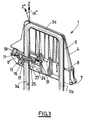
- the headrest 1 described in relation to Figures 1 to 5 is intended to be mounted on the back of a motor vehicle seat.
- This headrest 1 includes a frame 2 provided with at least one rod extending along an axis Z, that is to say in the vertical direction when the headrest 1 is mounted on the backrest seat, as well as a displacement and locking system in translation.
- the armature 2 conventionally formed in steel, includes two rods 3a, 3b linked together by a third rod 3c extending transversely in a direction perpendicular to the Z axis.
- the frame has a substantially inverted U shape, the end of the rods 3a, 3b opposite the rod 3c being intended to be inserted into the part upper part of the backrest.
- the frame 2 is intended to be fixedly mounted on the seat back.
- fixing sleeves are provided in the backrest, said sockets being arranged to receive the ends fixedly rods 3a and 3b.
- the headrest 1 also includes a casing 4 mounted movable in translation on rods 3a and 3b.
- the casing 4 is provided with orifices 5 arranged to receiving the rods 3a, 3b forming the frame.
- the housing 4 is formed of a material rigid, such as polypropylene, so as not only to form a support for the headrest support cushion, not shown, which is arranged above, but also a protective envelope for the displacement system and locking in translation of the casing 4 along the rods.
- the casing 4 is formed of two parts: a body upper 6 on which is mounted the support cushion, and a lower housing 7 intended to be placed inside said body 6 by interlocking, the housing 7 being arranged to form the lower part of the casing 4.
- the translational movement and locking system is integrated in the casing 4, and is provided, according to the embodiment shown, at the level of the rod 3a.
- the second rod 3b is housed in an orifice 8 of the casing 4 provided for this effect.
- the system comprises a rigid blocking piece 9 provided with an orifice 10 intended to receive the rod 3a.
- this rigid part 9 formed for example from a metallic material such as stainless steel, is a washer comprising an annular part provided with the orifice, a radial extension 11, as well as a wall 12 extending perpendicular to the surface of the workpiece blocking 9, and around a part of said surface.
- the locking piece 9 is arranged so that, in a locking position, the axis Z 'of the orifice 10 is inclined relative to the axis Z of a sufficient angle ⁇ to allow the blocking of the casing 4 along the rods 3a, 3b and so that, in a translation position, the axis Z 'is inclined relative to the axis Z by an angle ⁇ 'less than ⁇ to allow free translation of the housing.
- the displacement of part 9 between these two positions by bracing is made possible in particular by the rigid nature of the part 9 and by the size of the orifice 10 intended to receive the rod 3a.
- the system also includes an actuating part 13 of the blocking 9 comprising actuating means arranged to allow the reversible movement in rotation of the part 9 from the locking position towards the translation position.
- the actuating part 13 is provided with an orifice 14 intended to receive the rod 3a, and with a zone 15 of geometry arranged to receive the locking piece 9 in the position of blocking.
- the orifice 14 is of sufficient size to allow the translation of the actuating part 13 along an axis perpendicular to the Z axis, this translation being necessary for the actuation of the locking piece 9, as this will be described later.
- the actuating part 13 comprises a body provided with the orifice 14, on one of the walls of which a ramp is provided lower 16 forming means for actuating the blocking piece 9 between the two locking and translating positions.
- the actuating part 13 When mounting the system inside the casing 4, the actuating part 13 is arranged above the blocking part 9, the respective orifices 10, 14 of the two parts 9, 13 being arranged opposite one another.
- the system also includes a displacement spring 17 for displacement of the locking piece 9 between the locking position and the position of translation, said spring 17 being, in the variant shown in Figures 1 to 3, formed by a blade which is integrated into the locking piece 9. According to the variant shown in Figures 4 and 5, the spring 17 is not an integral part of the locking piece 9, but is associated with it by one of its ends 18.
- the displacement and translational locking system of the casing 4 comprises furthermore a device for controlling the actuating part 13.
- this control device comprises a button 19 manually operable by the user from outside the casing 4, said button 19 being located on a lateral face of the casing 4 for reasons of convenience.
- the casing 4 comprises a lateral opening 20 arranged to accommodate the button 19, said button 19 comprising a projection 21 coming in abutment against a face 22 of the actuating part 13.
- a washer 23 is provided around the button 19, said washer 23 being also arranged to partially penetrate into the lateral opening 20 of the casing 4.
- the displacement and translational locking system of the casing 4 comprises also a housing 24 provided in the casing 4, making it possible to receive at the minus the locking piece 9 and the actuating piece 13, the housing 24 being arranged to allow reversible actuation of the locking piece 9 from the locking position to the translation position.
- Housing 24 comprises an orifice 25 intended to receive the rod 3a and intended to be placed, during assembly of the system, opposite the orifices 10, 14 of the workpiece blocking 9 and the actuating part 13.
- the housing 24 is formed of a piece of guide 26 arranged to guide the actuating part in translation, and this by sliding an upper ramp 27 of the actuating part 13 on along the guide piece 26.
- This guide piece 26 comprises also an orifice 28 intended to receive the rod 3a, and is intended to be mounted on the lower housing 7 of the casing 4 so as to form therebetween housing 24, the guide piece 26 then being disposed above the piece actuation 13.
- the guide piece 26 comprises a part substantially flat 29 provided with the orifice 28, and feet 30 extending axially towards the lower part of the casing 4, these feet 30 being intended to be inserted by clipping into slots of complementary shape provided in the lower case 7.
- the housing 4 of the headrest comprises, from the top towards the bottom, the upper body 6 on which the support cushion is mounted, and in which is housed the control button 19, then successively the guide piece 26, the actuating part 13, the locking part 9, these three parts being arranged inside the lower housing 7, the stress spring 17 being compressed between the underside of the blocking piece 9 and a surface support of the lower housing 7. Thanks to this arrangement, the displacement and locking in translation of the casing 4 therefore has the advantage to be fully integrated in said housing.
- the actuating parts 13, guide 26 and the device control 19, 23 are conventionally made of plastic material, and can be obtained by an injection molding technique, which presents advantages in terms of costs and speed of manufacture.
- FIGS. 2 to 5 show the operation of the headrest 1 comprising such a displacement and locking system in translation of the casing 4 in the mode of embodiment considered, in relation to FIGS. 2 to 5.
- Figures 2 and 4 show the locking piece 9 in its position blocking of the casing 4
- FIGS. 3 and 5 show the blocking part 9 in the position allowing the translation of said casing 4.
- the locking piece 9 When the system is mounted as described above, the locking piece 9 is in the blocking position, in which it blocks the translation of the casing 4 by bracing. In this position, the locking piece 9 is arranged in zone 15 of the actuating part 13 provided for this purpose, so as to be inclined with respect to the perpendicular to the Z axis. The Z 'axis of the orifice 10 is then inclined at an angle ⁇ relative to the axis Z, the angle ⁇ being sufficient to secure the housing 4.
- a return spring 31 provided between the part actuator 13 and guide piece 26, and disposed around an extension 32 located on the actuating part 13, compresses against a wall of the guide piece 26.
- the lower ramp 16 of the actuating part 13 comes to bear on an outer surface of the locking piece 9, which causes the locking piece 9 to tip over and move rotation to the translation position, this displacement causing the compression of the stress spring 17.
- the part of blocking 9 is in a position substantially perpendicular to the Z axis, and the axis Z 'of the orifice 10 is inclined relative to the axis Z by an angle ⁇ ' less than ⁇ , of such that the walls of the orifice 10 no longer exert a significant force on the rod 3a.
- the translation of the casing 4 is free, in the two directions Z + and Z-. The user can then adjust the headrest 1 to the desired height.
- the system also allows the translation of the casing 4 in the direction Z +, that is to say towards the top of the vehicle, without pressing the button command 19. Indeed, the displacement of the casing 4 upwards induced, by the friction bias between the walls of the orifice 10 and the rod 3a, a decrease very low angle of bracing ⁇ , which allows the blocking piece 9 to get out of its braced position.
- the casing 4 can then be moved in translate freely upwards, in the direction Z +, to pass for example from its lowest position, shown in Figure 2a, to its lowest position high shown in Figure 2b.
- any pressure in Z- on the casing 4 exerts a pressure on the casing 4 on the washer 9 in its radial extension 11, which restores the condition of bracing.
Landscapes
- Engineering & Computer Science (AREA)
- Aviation & Aerospace Engineering (AREA)
- Transportation (AREA)
- Mechanical Engineering (AREA)
- Seats For Vehicles (AREA)
Applications Claiming Priority (2)
| Application Number | Priority Date | Filing Date | Title |
|---|---|---|---|
| FR0216392A FR2848931B1 (fr) | 2002-12-20 | 2002-12-20 | Appui-tete comprenant un systeme integre de deplacement et de blocage en translation |
| FR0216392 | 2002-12-20 |
Publications (1)
| Publication Number | Publication Date |
|---|---|
| EP1431110A1 true EP1431110A1 (de) | 2004-06-23 |
Family
ID=32338998
Family Applications (1)
| Application Number | Title | Priority Date | Filing Date |
|---|---|---|---|
| EP03293031A Withdrawn EP1431110A1 (de) | 2002-12-20 | 2003-12-04 | Kopfstütze mit einem integrierten Längsverstellungs- und Arretierungssystem |
Country Status (2)
| Country | Link |
|---|---|
| EP (1) | EP1431110A1 (de) |
| FR (1) | FR2848931B1 (de) |
Cited By (2)
| Publication number | Priority date | Publication date | Assignee | Title |
|---|---|---|---|---|
| EP3753784A1 (de) * | 2019-06-20 | 2020-12-23 | TESCA France | Kopfstütze für kraftfahrzeugsitz |
| WO2021110742A1 (de) * | 2019-12-03 | 2021-06-10 | Adient Engineering and IP GmbH | Unterbaugruppe zur stufenlosen einstellung einer kopfstütze für einen fahrzeugsitz, kopfstütze für einen fahrzeugsitz, sowie fahrzeugsitz |
Families Citing this family (3)
| Publication number | Priority date | Publication date | Assignee | Title |
|---|---|---|---|---|
| DE102013222417B4 (de) | 2013-11-05 | 2018-01-11 | Lear Corporation | Verstellbare Kopfstützenanordnung für Fahrzeugsitze |
| DE102017211720B4 (de) | 2016-07-20 | 2022-06-30 | Lear Corporation | Sitzaufbau mit einem einstellbaren Kopfstützenaufbau |
| DE102020211744A1 (de) | 2020-09-21 | 2022-03-24 | Volkswagen Aktiengesellschaft | Kopfstütze mit einer hinsichtlich eines Whiplash-Lastfalls optimierten Kopfstützen-Kontur |
Citations (10)
| Publication number | Priority date | Publication date | Assignee | Title |
|---|---|---|---|---|
| US4545618A (en) * | 1984-02-22 | 1985-10-08 | Tachikawa Spring Co., Ltd. | Head-rest device |
| FR2585648A1 (fr) * | 1985-08-02 | 1987-02-06 | Fiat Auto Spa | Appuie-tete reglable en hauteur |
| US4779929A (en) * | 1986-07-30 | 1988-10-25 | Fhs Stahlverformung Gmbh | Variable-height and variable-slant head rest with a center window for motor vehicles |
| EP0457177A2 (de) * | 1990-05-12 | 1991-11-21 | Adam Opel Aktiengesellschaft | Kopfstütze für Kraftfahrzeugsitze |
| FR2746065A1 (fr) * | 1996-03-18 | 1997-09-19 | Faure Bertrand Equipements Sa | Appui-tete pour siege de vehicule automobile |
| EP0916549A1 (de) * | 1997-11-14 | 1999-05-19 | Gestind M.B. Manifattura Di Bruzolo S.P.A | Kopfstütze für Kraftfahrzeugsitze |
| FR2803563A1 (fr) * | 2000-01-12 | 2001-07-13 | Faure Bertrand Equipements Sa | Siege de vehicule dote d'un appui-tete reglable en hauteur |
| US20020038969A1 (en) * | 2000-08-18 | 2002-04-04 | Whitmore Stuart Joseph | Seat headrest mounting |
| FR2821590A1 (fr) * | 2001-03-02 | 2002-09-06 | Cera | Dispositif de coulissement et de blocage d'une tige lisse, notamment pour le reglage d'appuis-tete pour sieges de vehicules automobiles |
| FR2833052A1 (fr) * | 2001-11-30 | 2003-06-06 | Cera | Systeme de deplacement et de blocage en translation d'une tige lisse, par arc-boutement d'une piece de blocage |
-
2002
- 2002-12-20 FR FR0216392A patent/FR2848931B1/fr not_active Expired - Fee Related
-
2003
- 2003-12-04 EP EP03293031A patent/EP1431110A1/de not_active Withdrawn
Patent Citations (10)
| Publication number | Priority date | Publication date | Assignee | Title |
|---|---|---|---|---|
| US4545618A (en) * | 1984-02-22 | 1985-10-08 | Tachikawa Spring Co., Ltd. | Head-rest device |
| FR2585648A1 (fr) * | 1985-08-02 | 1987-02-06 | Fiat Auto Spa | Appuie-tete reglable en hauteur |
| US4779929A (en) * | 1986-07-30 | 1988-10-25 | Fhs Stahlverformung Gmbh | Variable-height and variable-slant head rest with a center window for motor vehicles |
| EP0457177A2 (de) * | 1990-05-12 | 1991-11-21 | Adam Opel Aktiengesellschaft | Kopfstütze für Kraftfahrzeugsitze |
| FR2746065A1 (fr) * | 1996-03-18 | 1997-09-19 | Faure Bertrand Equipements Sa | Appui-tete pour siege de vehicule automobile |
| EP0916549A1 (de) * | 1997-11-14 | 1999-05-19 | Gestind M.B. Manifattura Di Bruzolo S.P.A | Kopfstütze für Kraftfahrzeugsitze |
| FR2803563A1 (fr) * | 2000-01-12 | 2001-07-13 | Faure Bertrand Equipements Sa | Siege de vehicule dote d'un appui-tete reglable en hauteur |
| US20020038969A1 (en) * | 2000-08-18 | 2002-04-04 | Whitmore Stuart Joseph | Seat headrest mounting |
| FR2821590A1 (fr) * | 2001-03-02 | 2002-09-06 | Cera | Dispositif de coulissement et de blocage d'une tige lisse, notamment pour le reglage d'appuis-tete pour sieges de vehicules automobiles |
| FR2833052A1 (fr) * | 2001-11-30 | 2003-06-06 | Cera | Systeme de deplacement et de blocage en translation d'une tige lisse, par arc-boutement d'une piece de blocage |
Cited By (3)
| Publication number | Priority date | Publication date | Assignee | Title |
|---|---|---|---|---|
| EP3753784A1 (de) * | 2019-06-20 | 2020-12-23 | TESCA France | Kopfstütze für kraftfahrzeugsitz |
| FR3097488A1 (fr) * | 2019-06-20 | 2020-12-25 | Tesca France | Appui-tête de siège de véhicule automobile |
| WO2021110742A1 (de) * | 2019-12-03 | 2021-06-10 | Adient Engineering and IP GmbH | Unterbaugruppe zur stufenlosen einstellung einer kopfstütze für einen fahrzeugsitz, kopfstütze für einen fahrzeugsitz, sowie fahrzeugsitz |
Also Published As
| Publication number | Publication date |
|---|---|
| FR2848931B1 (fr) | 2005-11-18 |
| FR2848931A1 (fr) | 2004-06-25 |
Similar Documents
| Publication | Publication Date | Title |
|---|---|---|
| FR2736012A1 (fr) | Mef nisme d'arret d'un appui-tete | |
| FR2849813A1 (fr) | Dispositif d'appui-tete pour siege de vehicule et siege de vehicule comportant un tel dispositif. | |
| FR2910401A1 (fr) | Appui-tete escamotable | |
| EP2953816B1 (de) | Kopfstütze für einen kraftfahrzeugsitz | |
| FR3036666A1 (fr) | Appui-tete de siege de vehicule et siege comportant un tel appui-tete | |
| FR2852066A1 (fr) | Systeme de deplacement et de blocage en translation d'une tige lisse, par arc-boutement d'une piece de blocage a l'aide d'un bouton de commande | |
| EP1431110A1 (de) | Kopfstütze mit einem integrierten Längsverstellungs- und Arretierungssystem | |
| EP0669221B1 (de) | Höhenverstellbare Armlehne für Kraftfahrzeuge | |
| EP0205379A1 (de) | Schloss, insbesondere für Sicherheitsgurte | |
| EP1316470B1 (de) | Einrichtung zur Längsverstellung und Arretierung eines glatten Stabes durch Momentensperre eines Sperrelementes | |
| FR2841510A1 (fr) | Accoudoir reglage en hauteur, notamment pour siege de vehicule automobile | |
| EP1910126A2 (de) | System zum verstellen und translatorischen arretieren eines stabs, insbesondere für eine kraftfahrzeugkopfstütze | |
| EP1473187A1 (de) | Sitz für Verkehrsmittel, insbesondere Lufttransporte | |
| EP1354756A1 (de) | Versetz- und Blockiereinrichtung der Translation einer Stütze, insbesondere für Kopfstützen in Kraftfahrzeugen | |
| FR2848932A1 (fr) | Appui-tete comprenant un systeme integre de deplacement et de blocage en rotation, et eventuellement en translation | |
| FR2886590A1 (fr) | Assemblage de siege rabattable de vehicule automobile | |
| FR2756787A1 (fr) | Dispositif de montage d'un accoudoir sur une colonne | |
| FR2823808A1 (fr) | Systeme de coulissement et de blocage d'une tige lisse au moyen d'un diaphragme, notamment pour siege de vehicule automobile | |
| FR2932430A1 (fr) | Fourreau de guidage d'appui-tete a deverrouillage securise. | |
| FR3017570A1 (fr) | Dispositif de reglage en hauteur d'un appuie-tete de siege de vehicule automobile | |
| EP2657074A1 (de) | Montagevorrichtung einer Kopfstütze auf der Rückenlehne eines Autositzes | |
| FR2877616A1 (fr) | Systeme de guidage et de blocage d'une tige crantee presentant un mecanisme simplifie | |
| FR2824115A1 (fr) | Systeme de coulissement et de blocage d'une tige lisse au moyen d'un ressort, notamment pour siege de vehicule automobile | |
| FR2986475A1 (fr) | Appui-tete de siege de vehicule automobile | |
| FR2863222A1 (fr) | Systeme de guidage et de blocage en translation d'une tige, notamment d'un appui-tete comprenant une epingle de pincement |
Legal Events
| Date | Code | Title | Description |
|---|---|---|---|
| PUAI | Public reference made under article 153(3) epc to a published international application that has entered the european phase |
Free format text: ORIGINAL CODE: 0009012 |
|
| AK | Designated contracting states |
Kind code of ref document: A1 Designated state(s): AT BE BG CH CY CZ DE DK EE ES FI FR GB GR HU IE IT LI LU MC NL PT RO SE SI SK TR |
|
| AX | Request for extension of the european patent |
Extension state: AL LT LV MK |
|
| 17P | Request for examination filed |
Effective date: 20041126 |
|
| AKX | Designation fees paid |
Designated state(s): AT BE BG CH CY CZ DE DK EE ES FI FR GB GR HU IE IT LI LU MC NL PT RO SE SI SK TR |
|
| 17Q | First examination report despatched |
Effective date: 20060727 |
|
| STAA | Information on the status of an ep patent application or granted ep patent |
Free format text: STATUS: THE APPLICATION IS DEEMED TO BE WITHDRAWN |
|
| 18D | Application deemed to be withdrawn |
Effective date: 20060701 |