EP1431110A1 - Headrest with an integrated translation movement and locking system - Google Patents
Headrest with an integrated translation movement and locking system Download PDFInfo
- Publication number
- EP1431110A1 EP1431110A1 EP03293031A EP03293031A EP1431110A1 EP 1431110 A1 EP1431110 A1 EP 1431110A1 EP 03293031 A EP03293031 A EP 03293031A EP 03293031 A EP03293031 A EP 03293031A EP 1431110 A1 EP1431110 A1 EP 1431110A1
- Authority
- EP
- European Patent Office
- Prior art keywords
- translation
- casing
- housing
- rod
- blocking
- Prior art date
- Legal status (The legal status is an assumption and is not a legal conclusion. Google has not performed a legal analysis and makes no representation as to the accuracy of the status listed.)
- Withdrawn
Links
Images


Classifications
-
- B—PERFORMING OPERATIONS; TRANSPORTING
- B60—VEHICLES IN GENERAL
- B60N—SEATS SPECIALLY ADAPTED FOR VEHICLES; VEHICLE PASSENGER ACCOMMODATION NOT OTHERWISE PROVIDED FOR
- B60N2/00—Seats specially adapted for vehicles; Arrangement or mounting of seats in vehicles
- B60N2/80—Head-rests
- B60N2/806—Head-rests movable or adjustable
- B60N2/809—Head-rests movable or adjustable vertically slidable
- B60N2/812—Head-rests movable or adjustable vertically slidable characterised by their locking devices
- B60N2/815—Release mechanisms, e.g. buttons
-
- B—PERFORMING OPERATIONS; TRANSPORTING
- B60—VEHICLES IN GENERAL
- B60N—SEATS SPECIALLY ADAPTED FOR VEHICLES; VEHICLE PASSENGER ACCOMMODATION NOT OTHERWISE PROVIDED FOR
- B60N2/00—Seats specially adapted for vehicles; Arrangement or mounting of seats in vehicles
- B60N2/80—Head-rests
- B60N2/806—Head-rests movable or adjustable
- B60N2/809—Head-rests movable or adjustable vertically slidable
- B60N2/812—Head-rests movable or adjustable vertically slidable characterised by their locking devices
- B60N2/821—Head-rests movable or adjustable vertically slidable characterised by their locking devices with continuous positioning
-
- B—PERFORMING OPERATIONS; TRANSPORTING
- B60—VEHICLES IN GENERAL
- B60N—SEATS SPECIALLY ADAPTED FOR VEHICLES; VEHICLE PASSENGER ACCOMMODATION NOT OTHERWISE PROVIDED FOR
- B60N2/00—Seats specially adapted for vehicles; Arrangement or mounting of seats in vehicles
- B60N2/80—Head-rests
- B60N2/894—Head-rests with rods solidly attached to the back-rest
Definitions
- the invention relates to a headrest, in particular for a vehicle seat automobile.
- a headrest for a motor vehicle seat must meet strict security imposing that in position of use, this one is firmly held in the position in which it was adjusted by the user. Furthermore, it it is necessary that the headrest is provided with a locking system intended to prevent its translation in the Z- direction, i.e. downwards, when this is not desired by the user. Such a translation is likely occur for example in the event of inadvertent support by a rear passenger.
- Head restraints for motor vehicle seats include a frame provided with two vertical rods, and a body fixed on the frame, said body on which is arranged the support cushion, being mounted at the upper end of the rods, the other end of which goes into the seat back.
- the invention therefore proposes an improvement of the adjustment systems. integrated in the body of the headrest, this system using the principle of bracing a locking piece so as to be easy to use and inexpensive manufacturing.
- This system provides an integrated setting, lockable and continuous, thus allowing an infinite number of adjustment positions.
- this system which uses a reduced number of parts, is mounting easy inside the headrest body.
- the headrest 1 described in relation to Figures 1 to 5 is intended to be mounted on the back of a motor vehicle seat.
- This headrest 1 includes a frame 2 provided with at least one rod extending along an axis Z, that is to say in the vertical direction when the headrest 1 is mounted on the backrest seat, as well as a displacement and locking system in translation.
- the armature 2 conventionally formed in steel, includes two rods 3a, 3b linked together by a third rod 3c extending transversely in a direction perpendicular to the Z axis.
- the frame has a substantially inverted U shape, the end of the rods 3a, 3b opposite the rod 3c being intended to be inserted into the part upper part of the backrest.
- the frame 2 is intended to be fixedly mounted on the seat back.
- fixing sleeves are provided in the backrest, said sockets being arranged to receive the ends fixedly rods 3a and 3b.
- the headrest 1 also includes a casing 4 mounted movable in translation on rods 3a and 3b.
- the casing 4 is provided with orifices 5 arranged to receiving the rods 3a, 3b forming the frame.
- the housing 4 is formed of a material rigid, such as polypropylene, so as not only to form a support for the headrest support cushion, not shown, which is arranged above, but also a protective envelope for the displacement system and locking in translation of the casing 4 along the rods.
- the casing 4 is formed of two parts: a body upper 6 on which is mounted the support cushion, and a lower housing 7 intended to be placed inside said body 6 by interlocking, the housing 7 being arranged to form the lower part of the casing 4.
- the translational movement and locking system is integrated in the casing 4, and is provided, according to the embodiment shown, at the level of the rod 3a.
- the second rod 3b is housed in an orifice 8 of the casing 4 provided for this effect.
- the system comprises a rigid blocking piece 9 provided with an orifice 10 intended to receive the rod 3a.
- this rigid part 9 formed for example from a metallic material such as stainless steel, is a washer comprising an annular part provided with the orifice, a radial extension 11, as well as a wall 12 extending perpendicular to the surface of the workpiece blocking 9, and around a part of said surface.
- the locking piece 9 is arranged so that, in a locking position, the axis Z 'of the orifice 10 is inclined relative to the axis Z of a sufficient angle ⁇ to allow the blocking of the casing 4 along the rods 3a, 3b and so that, in a translation position, the axis Z 'is inclined relative to the axis Z by an angle ⁇ 'less than ⁇ to allow free translation of the housing.
- the displacement of part 9 between these two positions by bracing is made possible in particular by the rigid nature of the part 9 and by the size of the orifice 10 intended to receive the rod 3a.
- the system also includes an actuating part 13 of the blocking 9 comprising actuating means arranged to allow the reversible movement in rotation of the part 9 from the locking position towards the translation position.
- the actuating part 13 is provided with an orifice 14 intended to receive the rod 3a, and with a zone 15 of geometry arranged to receive the locking piece 9 in the position of blocking.
- the orifice 14 is of sufficient size to allow the translation of the actuating part 13 along an axis perpendicular to the Z axis, this translation being necessary for the actuation of the locking piece 9, as this will be described later.
- the actuating part 13 comprises a body provided with the orifice 14, on one of the walls of which a ramp is provided lower 16 forming means for actuating the blocking piece 9 between the two locking and translating positions.
- the actuating part 13 When mounting the system inside the casing 4, the actuating part 13 is arranged above the blocking part 9, the respective orifices 10, 14 of the two parts 9, 13 being arranged opposite one another.
- the system also includes a displacement spring 17 for displacement of the locking piece 9 between the locking position and the position of translation, said spring 17 being, in the variant shown in Figures 1 to 3, formed by a blade which is integrated into the locking piece 9. According to the variant shown in Figures 4 and 5, the spring 17 is not an integral part of the locking piece 9, but is associated with it by one of its ends 18.
- the displacement and translational locking system of the casing 4 comprises furthermore a device for controlling the actuating part 13.
- this control device comprises a button 19 manually operable by the user from outside the casing 4, said button 19 being located on a lateral face of the casing 4 for reasons of convenience.
- the casing 4 comprises a lateral opening 20 arranged to accommodate the button 19, said button 19 comprising a projection 21 coming in abutment against a face 22 of the actuating part 13.
- a washer 23 is provided around the button 19, said washer 23 being also arranged to partially penetrate into the lateral opening 20 of the casing 4.
- the displacement and translational locking system of the casing 4 comprises also a housing 24 provided in the casing 4, making it possible to receive at the minus the locking piece 9 and the actuating piece 13, the housing 24 being arranged to allow reversible actuation of the locking piece 9 from the locking position to the translation position.
- Housing 24 comprises an orifice 25 intended to receive the rod 3a and intended to be placed, during assembly of the system, opposite the orifices 10, 14 of the workpiece blocking 9 and the actuating part 13.
- the housing 24 is formed of a piece of guide 26 arranged to guide the actuating part in translation, and this by sliding an upper ramp 27 of the actuating part 13 on along the guide piece 26.
- This guide piece 26 comprises also an orifice 28 intended to receive the rod 3a, and is intended to be mounted on the lower housing 7 of the casing 4 so as to form therebetween housing 24, the guide piece 26 then being disposed above the piece actuation 13.
- the guide piece 26 comprises a part substantially flat 29 provided with the orifice 28, and feet 30 extending axially towards the lower part of the casing 4, these feet 30 being intended to be inserted by clipping into slots of complementary shape provided in the lower case 7.
- the housing 4 of the headrest comprises, from the top towards the bottom, the upper body 6 on which the support cushion is mounted, and in which is housed the control button 19, then successively the guide piece 26, the actuating part 13, the locking part 9, these three parts being arranged inside the lower housing 7, the stress spring 17 being compressed between the underside of the blocking piece 9 and a surface support of the lower housing 7. Thanks to this arrangement, the displacement and locking in translation of the casing 4 therefore has the advantage to be fully integrated in said housing.
- the actuating parts 13, guide 26 and the device control 19, 23 are conventionally made of plastic material, and can be obtained by an injection molding technique, which presents advantages in terms of costs and speed of manufacture.
- FIGS. 2 to 5 show the operation of the headrest 1 comprising such a displacement and locking system in translation of the casing 4 in the mode of embodiment considered, in relation to FIGS. 2 to 5.
- Figures 2 and 4 show the locking piece 9 in its position blocking of the casing 4
- FIGS. 3 and 5 show the blocking part 9 in the position allowing the translation of said casing 4.
- the locking piece 9 When the system is mounted as described above, the locking piece 9 is in the blocking position, in which it blocks the translation of the casing 4 by bracing. In this position, the locking piece 9 is arranged in zone 15 of the actuating part 13 provided for this purpose, so as to be inclined with respect to the perpendicular to the Z axis. The Z 'axis of the orifice 10 is then inclined at an angle ⁇ relative to the axis Z, the angle ⁇ being sufficient to secure the housing 4.
- a return spring 31 provided between the part actuator 13 and guide piece 26, and disposed around an extension 32 located on the actuating part 13, compresses against a wall of the guide piece 26.
- the lower ramp 16 of the actuating part 13 comes to bear on an outer surface of the locking piece 9, which causes the locking piece 9 to tip over and move rotation to the translation position, this displacement causing the compression of the stress spring 17.
- the part of blocking 9 is in a position substantially perpendicular to the Z axis, and the axis Z 'of the orifice 10 is inclined relative to the axis Z by an angle ⁇ ' less than ⁇ , of such that the walls of the orifice 10 no longer exert a significant force on the rod 3a.
- the translation of the casing 4 is free, in the two directions Z + and Z-. The user can then adjust the headrest 1 to the desired height.
- the system also allows the translation of the casing 4 in the direction Z +, that is to say towards the top of the vehicle, without pressing the button command 19. Indeed, the displacement of the casing 4 upwards induced, by the friction bias between the walls of the orifice 10 and the rod 3a, a decrease very low angle of bracing ⁇ , which allows the blocking piece 9 to get out of its braced position.
- the casing 4 can then be moved in translate freely upwards, in the direction Z +, to pass for example from its lowest position, shown in Figure 2a, to its lowest position high shown in Figure 2b.
- any pressure in Z- on the casing 4 exerts a pressure on the casing 4 on the washer 9 in its radial extension 11, which restores the condition of bracing.
Abstract
Description
L'invention concerne un appui-tête, notamment pour siège de véhicule automobile.The invention relates to a headrest, in particular for a vehicle seat automobile.
Un appui-tête pour siège de véhicule automobile doit répondre à des normes de sécurité strictes imposant qu'en position d'utilisation, celui-ci soit fermement maintenu dans la position dans laquelle il a été réglé par l'utilisateur. En outre, il est nécessaire que l'appui-tête soit pourvu d'un système de blocage destiné à empêcher sa translation dans la direction Z-, c'est-à-dire vers le bas, lorsque celle-ci n'est pas souhaitée par l'utilisateur. Une telle translation est susceptible de survenir par exemple en cas d'appui par inadvertance d'un passager arrière.A headrest for a motor vehicle seat must meet strict security imposing that in position of use, this one is firmly held in the position in which it was adjusted by the user. Furthermore, it it is necessary that the headrest is provided with a locking system intended to prevent its translation in the Z- direction, i.e. downwards, when this is not desired by the user. Such a translation is likely occur for example in the event of inadvertent support by a rear passenger.
Les appuis-tête pour sièges de véhicule automobile comprennent une armature pourvue de deux tiges verticales, et un corps fixé sur l'armature, ledit corps, sur lequel est disposé le coussin d'appui, étant monté à l'extrémité supérieure des tiges dont l'autre extrémité pénètre dans le dossier du siège.Head restraints for motor vehicle seats include a frame provided with two vertical rods, and a body fixed on the frame, said body on which is arranged the support cushion, being mounted at the upper end of the rods, the other end of which goes into the seat back.
Pour le réglage en hauteur de tels appuis-tête, on connaít déjà des systèmes intégrés dans le corps de l'appui-tête. Toutefois, pour répondre au cahier des charges imposant des normes de sécurité de plus en plus strictes, il est nécessaire de prévoir des systèmes de réglage de l'appui-tête plus robustes, et ce sans en augmenter le coût.For the height adjustment of such headrests, we already know systems integrated into the body of the headrest. However, to meet the specifications charges imposing increasingly stringent security standards it is necessary to provide more robust headrest adjustment systems, and without increasing the cost.
L'invention propose donc un perfectionnement des systèmes de réglage intégrés dans le corps de l'appui-tête, ce système utilisant le principe de l'arc-boutement d'une pièce de blocage de sorte à être d'utilisation simple et de fabrication peu coûteuse. Ce système permet d'obtenir un réglage intégré, verrouillable et continu, et d'autoriser ainsi une infinité de positions de réglage.The invention therefore proposes an improvement of the adjustment systems. integrated in the body of the headrest, this system using the principle of bracing a locking piece so as to be easy to use and inexpensive manufacturing. This system provides an integrated setting, lockable and continuous, thus allowing an infinite number of adjustment positions.
En outre, ce système, qui utilise un nombre réduit de pièces, est de montage aisé à l'intérieur du corps de l'appui-tête.In addition, this system, which uses a reduced number of parts, is mounting easy inside the headrest body.
A cet effet, l'invention concerne un appui-tête, notamment pour siège de véhicule automobile, du type comprenant une armature pourvue d'au moins une tige qui s'étend suivant un axe Z et destinée à être insérée dans la partie supérieure du dossier du siège, un carter monté mobile en translation sur la tige, sur lequel est disposé un coussin d'appui, et un système de déplacement et de blocage en translation du carter le long de la tige intégré dans ledit carter, ledit système comprenant :
- une pièce de blocage rigide pourvue d'un orifice destiné à recevoir la tige, ladite pièce étant agencée pour que, dans une position de blocage, l'axe Z' de l'orifice soit incliné par rapport à l'axe Z d'un angle α suffisant pour permettre le blocage du carter le long de la tige, et, dans une position de translation, l'axe Z' soit incliné par rapport à l'axe Z d'un angle α' inférieur à α, pour permettre la translation libre du carter le long de la tige ;
- une pièce d'actionnement de ladite pièce de blocage comprenant des moyens d'actionnement agencés pour permettre le déplacement réversible en rotation de la pièce depuis la position de blocage vers la position de translation ;
- un dispositif de commande de la pièce d'actionnement ;
- un logement prévu dans le carter, au moins la pièce de blocage et la pièce d'actionnement étant disposés dans le logement, ledit logement étant agencé pour permettre l'actionnement réversible de la pièce de blocage depuis la position de blocage vers la position de translation.
- a rigid blocking part provided with an orifice intended to receive the rod, said part being arranged so that, in a blocking position, the axis Z ′ of the orifice is inclined relative to the axis Z of a angle α sufficient to allow blocking of the casing along the rod, and, in a translation position, the axis Z 'is inclined relative to the axis Z by an angle α' less than α, to allow the free translation of the casing along the rod;
- an actuating part of said blocking part comprising actuating means arranged to allow the reversible movement in rotation of the part from the blocking position to the translation position;
- a device for controlling the actuating part;
- a housing provided in the housing, at least the blocking part and the actuating part being arranged in the housing, said housing being arranged to allow reversible actuation of the blocking part from the blocking position to the translation position .
D'autres objets et avantages de l'invention apparaítront au cours de la description qui suit, faite en référence aux dessins annexés dans lesquels :
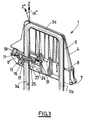
- la figure 1 est une vue éclatée partielle d'un appui-tête montrant l'armature, le carter, et les pièces formant le système de déplacement et de blocage en translation de l'appui-tête, selon un mode de réalisation ;
- les figures 2a et 2b sont des vues en perspective de l'appui-tête de la figure 1, montrant partiellement l'intérieur de l'appui-tête dans lequel est intégré le système de déplacement et de blocage, en position de blocage ; la figure 2a montre le carter en position basse par rapport à l'armature, et la figure 2b montre le carter en position haute par rapport à l'armature ;
- la figure 3 est une vue analogue à la figure 2a, le système de déplacement et de blocage étant en position de translation ;
- la figure 4 est une vue schématique en coupe montrant le système de déplacement et de blocage en translation de l'appui-tête après intégration dans le carter, selon une variante du mode de réalisation représenté sur les figures 2 et 3, le système étant en position de blocage ;
- la figure 5 est une vue analogue à la figure 4, le système étant en position de translation.
- Figure 1 is a partial exploded view of a headrest showing the frame, the housing, and the parts forming the displacement and locking system in translation of the headrest, according to one embodiment;
- Figures 2a and 2b are perspective views of the headrest of Figure 1, partially showing the interior of the headrest in which the displacement and locking system is integrated, in the locking position; Figure 2a shows the housing in the low position relative to the frame, and Figure 2b shows the housing in the high position relative to the frame;
- Figure 3 is a view similar to Figure 2a, the displacement and locking system being in the translation position;
- Figure 4 is a schematic sectional view showing the system for moving and blocking in translation of the headrest after integration into the housing, according to a variant of the embodiment shown in Figures 2 and 3, the system being blocking position;
- Figure 5 is a view similar to Figure 4, the system being in the translation position.
L'appui-tête 1 décrit en relation avec les figures 1 à 5 est destiné à être monté
sur le dossier d'un siège de véhicule automobile. Cet appui-tête 1 comprend
une armature 2 pourvue d'au moins une tige s'étendant suivant un axe Z, c'est-à-dire
dans la direction verticale lorsque l'appui-tête 1 est monté sur le dossier
de siège, ainsi qu'un système de déplacement et de blocage en translation.The
Dans le mode de réalisation représenté, l'armature 2, classiquement formée en
acier, comprend deux tiges 3a, 3b reliées entre elles par une troisième tige 3c
s'étendant transversalement dans une direction perpendiculaire à l'axe Z.
L'armature présente sensiblement une forme de U renversé, l'extrémité des
tiges 3a, 3b opposée à la tige 3c étant destinée à être insérée dans la partie
supérieure du dossier. L'armature 2 est destinée à être montée fixement sur le
dossier du siège. A cet effet, des douilles de fixation sont prévues dans le
dossier, lesdites douilles étant agencées pour recevoir fixement les extrémités
des tiges 3a et 3b.In the embodiment shown, the armature 2, conventionally formed in
steel, includes two
L'appui-tête 1 comprend également un carter 4 monté mobile en translation sur
les tiges 3a et 3b. A cet effet, le carter 4 est pourvu d'orifices 5 agencés pour
recevoir les tiges 3a, 3b formant l'armature. Le carter 4 est formé d'un matériau
rigide, tel que du polypropylène, de sorte à former non seulement un support
pour le coussin d'appui de l'appui-tête, non représenté, qui est disposé dessus,
mais également une enveloppe protectrice pour le système de déplacement et
de blocage en translation du carter 4 le long des tiges.The
Selon la réalisation représentée, le carter 4 est formé de deux parties : un corps
supérieur 6 sur lequel est monté le coussin d'appui, et un boítier inférieur 7
destiné à être disposé à l'intérieur dudit corps 6 par emboítement, le boítier 7
étant agencé pour former la partie inférieure du carter 4.According to the embodiment shown, the
Le système de déplacement et de blocage en translation est intégré dans le
carter 4, et est prévu, selon le mode de réalisation représenté, au niveau de la
tige 3a. La deuxième tige 3b est logée dans un orifice 8 du carter 4 prévu à cet
effet.The translational movement and locking system is integrated in the
Le système comprend une pièce de blocage rigide 9 pourvue d'un orifice 10
destiné à recevoir la tige 3a. Selon la réalisation représentée, cette pièce rigide
9, formée par exemple d'un matériau métallique tel que l'inox, est une rondelle
comprenant une partie annulaire pourvue de l'orifice, une extension radiale 11,
ainsi qu'une paroi 12 s'étendant perpendiculairement à la surface de la pièce de
blocage 9, et autour d'une partie de ladite surface.The system comprises a
La pièce de blocage 9 est agencée pour que, dans une position de blocage,
l'axe Z' de l'orifice 10 soit incliné par rapport à l'axe Z d'un angle α suffisant
pour permettre le blocage du carter 4 le long des tiges 3a, 3b et pour que, dans
une position de translation, l'axe Z' soit incliné par rapport à l'axe Z d'un angle
α' inférieur à α pour permettre la translation libre du carter. Le déplacement de
la pièce 9 entre ces deux positions par arc-boutement est rendu possible
notamment par le caractère rigide de la pièce 9 et par la taille de l'orifice 10
destiné à recevoir la tige 3a.The
Le système comprend également une pièce d'actionnement 13 de la pièce de
blocage 9 comprenant des moyens d'actionnement agencés pour permettre le
déplacement réversible en rotation de la pièce 9 depuis la position de blocage
vers la position de translation. The system also includes an
Selon le mode de réalisation représenté, la pièce d'actionnement 13 est
pourvue d'un orifice 14 destiné à recevoir la tige 3a, et d'une zone 15 de
géométrie agencée pour recevoir la pièce de blocage 9 dans la position de
blocage. L'orifice 14 est de taille suffisante pour permettre la translation de la
pièce d'actionnement 13 selon un axe perpendiculaire à l'axe Z, cette
translation étant nécessaire à l'actionnement de la pièce de blocage 9, comme
cela sera décrit plus loin. La pièce d'actionnement 13 comprend un corps
pourvu de l'orifice 14, sur l'une des parois duquel est prévue une rampe
inférieure 16 formant moyen d'actionnement de la pièce de blocage 9 entre les
deux positions de blocage et de translation.According to the embodiment shown, the actuating
Lors du montage du système à l'intérieur du carter 4, la pièce d'actionnement
13 est disposée au-dessus de la pièce de blocage 9, les orifices respectifs 10,
14 des deux pièces 9, 13 étant disposés en regard l'un de l'autre.When mounting the system inside the
Le système comprend également un ressort de contrainte 17 du déplacement
de la pièce de blocage 9 entre la position de blocage et la position de
translation, ledit ressort 17 étant, dans la variante représentée sur les figures 1
à 3, formé d'une lame qui est intégrée à la pièce de blocage 9. Selon la variante
représentée sur les figures 4 et 5, le ressort 17 ne fait pas partie intégrante de
la pièce de blocage 9, mais y est associé par l'une de ses extrémités 18.The system also includes a
Le système de déplacement et de blocage en translation du carter 4 comprend
en outre un dispositif de commande de la pièce d'actionnement 13. Selon la
réalisation représentée, ce dispositif de commande comprend un bouton 19
actionnable manuellement par l'utilisateur depuis l'extérieur du carter 4, ledit
bouton 19 étant situé sur une face latérale du carter 4 pour des raisons de
commodité. A cet effet, le carter 4 comprend une ouverture latérale 20 agencée
pour loger le bouton 19, ledit bouton 19 comprenant une saillie 21 venant en
butée contre une face 22 de la pièce d'actionnement 13. En outre, une rondelle
de finition 23 est prévue autour du bouton 19, ladite rondelle 23 étant
également agencée pour pénétrer partiellement dans l'ouverture latérale 20 du
carter 4.The displacement and translational locking system of the
Le système de déplacement et de blocage en translation du carter 4 comprend
également un logement 24 prévu dans le carter 4, permettant de recevoir au
moins la pièce de blocage 9 et la pièce d'actionnement 13, le logement 24 étant
agencé pour permettre l'actionnement réversible de la pièce de blocage 9
depuis la position de blocage vers la position de translation. Le logement 24
comprend un orifice 25 destiné à recevoir la tige 3a et prévu pour être placé,
lors du montage du système, en regard des orifices 10, 14 de la pièce de
blocage 9 et de la pièce d'actionnement 13.The displacement and translational locking system of the
Selon la réalisation représentée, le logement 24 est formé d'une pièce de
guidage 26 agencée pour guider en translation la pièce d'actionnement, et ce
par coulissement d'une rampe supérieure 27 de la pièce d'actionnement 13 le
long de la pièce de guidage 26. Cette pièce de guidage 26 comprend
également un orifice 28 destiné à recevoir la tige 3a, et est destinée à être
montée sur le boítier inférieur 7 du carter 4 de sorte à former entre eux le
logement 24, la pièce de guidage 26 étant alors disposée au-dessus de la pièce
d'actionnement 13. A cet effet, la pièce de guidage 26 comprend une partie
sensiblement plane 29 munie de l'orifice 28, et des pieds 30 s'étendant
axialement vers la partie inférieure du carter 4, ces pieds 30 étant destinés à
être insérés par clipsage dans des logements de forme complémentaire prévus
dans le boítier inférieur 7.According to the embodiment shown, the
De la sorte, une fois monté, le carter 4 de l'appui-tête comprend, du haut vers le
bas, le corps supérieur 6 sur lequel est monté le coussin d'appui, et dans lequel
est logé le bouton de commande 19, puis successivement la pièce de guidage
26, la pièce d'actionnement 13, la pièce de blocage 9, ces trois pièces étant
disposées à l'intérieur du boítier inférieur 7, le ressort de contrainte 17 étant
comprimé entre la face inférieure de la pièce de blocage 9 et une surface
d'appui du boítier inférieur 7. Grâce à cet agencement, le système de
déplacement et de blocage en translation du carter 4 présente donc l'avantage
d'être complètement intégré dans ledit carter.In this way, once mounted, the
Les pièces d'actionnement 13, de guidage 26 ainsi que le dispositif de
commande 19, 23 sont classiquement en matériau plastique, et peuvent être
obtenus par une technique de moulage par injection, ce qui présente des
avantages en termes de coûts et de rapidité de fabrication.The
On décrit à présent le fonctionnement de l'appui-tête 1 comprenant un tel
système de déplacement et de blocage en translation du carter 4 dans le mode
de réalisation considéré, en relation avec les figures 2 à 5. Il est à préciser que
les figures 2 et 4 représentent la pièce de blocage 9 dans sa position de
blocage du carter 4, et les figures 3 et 5 représentent la pièce de blocage 9
dans la position permettant la translation dudit carter 4.We now describe the operation of the
Lorsque le système est monté comme décrit plus haut, la pièce de blocage 9
est dans la position de blocage, dans laquelle elle bloque la translation du
carter 4 par arc-boutement. Dans cette position, la pièce de blocage 9 est
disposée dans la zone 15 de la pièce d'actionnement 13 prévue à cet effet, de
sorte à être inclinée par rapport à la perpendiculaire à l'axe Z. L'axe Z' de
l'orifice 10 est alors incliné d'un angle α par rapport à l'axe Z, l'angle α étant
suffisant pour assurer le blocage du carter 4.When the system is mounted as described above, the
Pour permettre la libre translation du carter 4 dans la direction Z-, il est
nécessaire d'actionner le bouton de commande 19 en le poussant vers
l'intérieur du carter 4 (figures 3 et 5), ce qui permet également la libre
translation du carter dans la direction Z+. Cette action entraíne en effet la
translation de la pièce d'actionnement 13 dans la direction perpendiculaire à
l'axe Z, vers l'intérieur du carter 4, la course suivie par la pièce d'actionnement
13 lors de cette translation étant imposée et limitée par la présence de la pièce
de guidage 26. To allow free translation of the
En outre, au fur et à mesure de la translation de la pièce d'actionnement 13
vers l'intérieur du carter 4, un ressort de rappel 31 prévu entre la pièce
d'actionnement 13 et la pièce de guidage 26, et disposé autour d'une extension
32 située sur la pièce d'actionnement 13, se comprime contre une paroi de la
pièce de guidage 26.In addition, as the
Au cours de cette translation, la rampe inférieure 16 de la pièce d'actionnement
13 vient en appui sur une surface extérieure de la pièce de blocage 9, ce qui
provoque le basculement de la pièce de blocage 9 et son déplacement par
rotation jusqu'à la position de translation, ce déplacement provoquant la
compression du ressort de contrainte 17. Dans cette position, la pièce de
blocage 9 est dans une position sensiblement perpendiculaire à l'axe Z, et l'axe
Z' de l'orifice 10 est incliné par rapport à l'axe Z d'un angle α' inférieur à α, de
telle sorte que les parois de l'orifice 10 n'exercent plus un effort significatif sur la
tige 3a. Ainsi, la translation du carter 4 est libre, dans les deux directions Z+ et
Z-. L'utilisateur peut alors régler l'appui-tête 1 à la hauteur souhaitée.During this translation, the
Lorsque ce réglage est réalisé, le fait de relâcher le bouton 19 entraíne le retour
de la pièce d'actionnement 13 dans sa position initiale, toujours par translation,
ce retour étant assisté par le ressort de rappel 31. Cette translation a pour effet
de désengager l'appui exercé par la pièce d'actionnement 13 sur la pièce de
blocage 9, de sorte que celle-ci puisse revenir dans la position de blocage, sous
l'action du ressort de contrainte 17.When this adjustment is made, releasing the
Le système permet en outre la translation du carter 4 dans la direction Z+,
c'est-à-dire vers le haut du véhicule, et ce sans actionner le bouton de
commande 19. En effet, le déplacement du carter 4 vers le haut induit, par le
biais du frottement entre les parois de l'orifice 10 et la tige 3a, une diminution
très faible de l'angle α d'arc-boutement, ce qui permet à la pièce de blocage 9
de sortir de sa position arc-boutée. Le carter 4 peut alors être déplacé en
translation librement vers le haut, dans la direction Z+, pour passer par exemple
de sa position la plus basse, représentée sur la figure 2a, à sa position la plus
haute représentée sur la figure 2b. The system also allows the translation of the
Et, lorsque le déplacement en Z+ du carter 4 est interrompu par l'utilisateur,
toute pression en Z- sur le carter 4 exerce une pression du carter 4 sur la
rondelle 9 en son extension radiale 11, ce qui rétablit la condition d'arc-boutement.And, when the displacement in Z + of the
Claims (7)
Applications Claiming Priority (2)
| Application Number | Priority Date | Filing Date | Title |
|---|---|---|---|
| FR0216392A FR2848931B1 (en) | 2002-12-20 | 2002-12-20 | HEADREST COMPRISING AN INTEGRATED TRANSLATION DISPLACEMENT AND BLOCKING SYSTEM |
| FR0216392 | 2002-12-20 |
Publications (1)
| Publication Number | Publication Date |
|---|---|
| EP1431110A1 true EP1431110A1 (en) | 2004-06-23 |
Family
ID=32338998
Family Applications (1)
| Application Number | Title | Priority Date | Filing Date |
|---|---|---|---|
| EP03293031A Withdrawn EP1431110A1 (en) | 2002-12-20 | 2003-12-04 | Headrest with an integrated translation movement and locking system |
Country Status (2)
| Country | Link |
|---|---|
| EP (1) | EP1431110A1 (en) |
| FR (1) | FR2848931B1 (en) |
Cited By (2)
| Publication number | Priority date | Publication date | Assignee | Title |
|---|---|---|---|---|
| EP3753784A1 (en) * | 2019-06-20 | 2020-12-23 | TESCA France | Headrest for a motor vehicle seat |
| WO2021110742A1 (en) * | 2019-12-03 | 2021-06-10 | Adient Engineering and IP GmbH | Subassembly for the continuous adjustment of a head rest for a vehicle seat, head rest for a vehicle seat, and vehicle seat |
Families Citing this family (3)
| Publication number | Priority date | Publication date | Assignee | Title |
|---|---|---|---|---|
| DE102013222417B4 (en) | 2013-11-05 | 2018-01-11 | Lear Corporation | Adjustable headrest assembly for vehicle seats |
| DE102017211720B4 (en) | 2016-07-20 | 2022-06-30 | Lear Corporation | Seat assembly with an adjustable headrest assembly |
| DE102020211744A1 (en) | 2020-09-21 | 2022-03-24 | Volkswagen Aktiengesellschaft | Headrest with a headrest contour optimized with regard to a whiplash load case |
Citations (10)
| Publication number | Priority date | Publication date | Assignee | Title |
|---|---|---|---|---|
| US4545618A (en) * | 1984-02-22 | 1985-10-08 | Tachikawa Spring Co., Ltd. | Head-rest device |
| FR2585648A1 (en) * | 1985-08-02 | 1987-02-06 | Fiat Auto Spa | Adjustable-height headrest |
| US4779929A (en) * | 1986-07-30 | 1988-10-25 | Fhs Stahlverformung Gmbh | Variable-height and variable-slant head rest with a center window for motor vehicles |
| EP0457177A2 (en) * | 1990-05-12 | 1991-11-21 | Adam Opel Aktiengesellschaft | Headrest for car seats |
| FR2746065A1 (en) * | 1996-03-18 | 1997-09-19 | Faure Bertrand Equipements Sa | Vehicle seat head rest |
| EP0916549A1 (en) * | 1997-11-14 | 1999-05-19 | Gestind M.B. Manifattura Di Bruzolo S.P.A | Headrest for motor-vehicle seats |
| FR2803563A1 (en) * | 2000-01-12 | 2001-07-13 | Faure Bertrand Equipements Sa | Height adjustable headrest for motor vehicle seat has rigid tube attached to support tube on backrest and adjusted by pivoting movement |
| US20020038969A1 (en) * | 2000-08-18 | 2002-04-04 | Whitmore Stuart Joseph | Seat headrest mounting |
| FR2821590A1 (en) * | 2001-03-02 | 2002-09-06 | Cera | Sliding and locking device for vehicle seat headrest rod comprises fixed part, receiving rod, and movable part and deformable part with hole for friction retention of rod |
| FR2833052A1 (en) * | 2001-11-30 | 2003-06-06 | Cera | SYSTEM FOR MOVING AND LOCKING IN TRANSLATION OF A SMOOTH ROD, BY ARC-BOUTEMENT OF A LOCKING PIECE |
-
2002
- 2002-12-20 FR FR0216392A patent/FR2848931B1/en not_active Expired - Fee Related
-
2003
- 2003-12-04 EP EP03293031A patent/EP1431110A1/en not_active Withdrawn
Patent Citations (10)
| Publication number | Priority date | Publication date | Assignee | Title |
|---|---|---|---|---|
| US4545618A (en) * | 1984-02-22 | 1985-10-08 | Tachikawa Spring Co., Ltd. | Head-rest device |
| FR2585648A1 (en) * | 1985-08-02 | 1987-02-06 | Fiat Auto Spa | Adjustable-height headrest |
| US4779929A (en) * | 1986-07-30 | 1988-10-25 | Fhs Stahlverformung Gmbh | Variable-height and variable-slant head rest with a center window for motor vehicles |
| EP0457177A2 (en) * | 1990-05-12 | 1991-11-21 | Adam Opel Aktiengesellschaft | Headrest for car seats |
| FR2746065A1 (en) * | 1996-03-18 | 1997-09-19 | Faure Bertrand Equipements Sa | Vehicle seat head rest |
| EP0916549A1 (en) * | 1997-11-14 | 1999-05-19 | Gestind M.B. Manifattura Di Bruzolo S.P.A | Headrest for motor-vehicle seats |
| FR2803563A1 (en) * | 2000-01-12 | 2001-07-13 | Faure Bertrand Equipements Sa | Height adjustable headrest for motor vehicle seat has rigid tube attached to support tube on backrest and adjusted by pivoting movement |
| US20020038969A1 (en) * | 2000-08-18 | 2002-04-04 | Whitmore Stuart Joseph | Seat headrest mounting |
| FR2821590A1 (en) * | 2001-03-02 | 2002-09-06 | Cera | Sliding and locking device for vehicle seat headrest rod comprises fixed part, receiving rod, and movable part and deformable part with hole for friction retention of rod |
| FR2833052A1 (en) * | 2001-11-30 | 2003-06-06 | Cera | SYSTEM FOR MOVING AND LOCKING IN TRANSLATION OF A SMOOTH ROD, BY ARC-BOUTEMENT OF A LOCKING PIECE |
Cited By (3)
| Publication number | Priority date | Publication date | Assignee | Title |
|---|---|---|---|---|
| EP3753784A1 (en) * | 2019-06-20 | 2020-12-23 | TESCA France | Headrest for a motor vehicle seat |
| FR3097488A1 (en) * | 2019-06-20 | 2020-12-25 | Tesca France | Motor vehicle seat headrest |
| WO2021110742A1 (en) * | 2019-12-03 | 2021-06-10 | Adient Engineering and IP GmbH | Subassembly for the continuous adjustment of a head rest for a vehicle seat, head rest for a vehicle seat, and vehicle seat |
Also Published As
| Publication number | Publication date |
|---|---|
| FR2848931A1 (en) | 2004-06-25 |
| FR2848931B1 (en) | 2005-11-18 |
Similar Documents
| Publication | Publication Date | Title |
|---|---|---|
| FR2736012A1 (en) | MEF STOP NISM OF A HEADREST | |
| FR2849813A1 (en) | Head-rest device for vehicle seat, has mobile screw-locking device moving a head-rest to retracted position and resetting head-rest from retracted position to stopping position when in unobtrusive and active positions, respectively | |
| FR2910401A1 (en) | Adjustable headrest for backrest of motor vehicle seat, has hook triggered by depressing rod in backrest till depressing position is reached, where hook rotates body relative to rod to bring body from usage position to non-usage position | |
| EP2953816B1 (en) | Headrest for a motor vehicle seat | |
| FR3036666A1 (en) | VEHICLE SEAT HEADREST AND SEAT COMPRISING SUCH A HEADREST | |
| FR2852066A1 (en) | Rod e.g. smooth rod, moving and blocking system for head restraint height adjustment, has activating device with control button that moves blocking piece from one position to another position when button is pressed to active position | |
| EP1431110A1 (en) | Headrest with an integrated translation movement and locking system | |
| EP0205379A1 (en) | Buckle, in particular for safety belts | |
| EP0669221B1 (en) | Height adjustable armrest for automotive vehicles | |
| EP1316470B1 (en) | Device for translational moving and arresting of a smooth bar by torque lock of a blocking element | |
| FR2841510A1 (en) | Adjustable-height arm rest, especially for motor vehicle seat, has housing with cavity for sliding support and height adjuster | |
| EP1910126A2 (en) | System for adjusting and locking in translation a rod, in particular for a motor vehicle headrest | |
| EP1473187A1 (en) | Seat for transport vehicles, especially air transport | |
| EP1354756A1 (en) | Shifting and translation blocking system for a rod, especially for car head-rests | |
| FR2848932A1 (en) | Vehicle seat head support, has case arranged to accommodate blockage unit and operating unit, where operating unit enables reversible displacement of blockage unit from position of blockage towards position of rotation | |
| FR2756787A1 (en) | DEVICE FOR MOUNTING AN ARMREST ON A COLUMN | |
| FR2823808A1 (en) | Sliding and locking system for automobile seat headrest rod sliding in sheath comprises diaphragm with orifice receiving rod | |
| FR2932430A1 (en) | SECURED UNLOCKING HEAD LEVER GUIDE SLIDER. | |
| FR3017570A1 (en) | DEVICE FOR ADJUSTING THE HEIGHT OF A HEADREST FOR A MOTOR VEHICLE SEAT | |
| EP2657074A1 (en) | Device for installing a headrest on a backrest of an automobile seat | |
| FR2877616A1 (en) | Rod guiding and blocking system for adjusting height of motor vehicle`s headrest, has pin arranged to be in stress between part and rod when rod is disposed in orifice by using support of elastic part against wall of housing | |
| FR2824115A1 (en) | Locking and sliding system for automobile seat headrest rod sliding in sleeve comprises spring connected to sleeve and unlocking device causing spring compression | |
| FR2986475A1 (en) | Headrest for motor vehicle seat, has connection cable whose actuation device actuates bolt toward unlocking position in opposition of average spring, where actuation device is connected at end of cable | |
| FR2863222A1 (en) | Rod`s e.g. headrest, movement guiding and blocking system for motor vehicle, has spring with two branches connected by elastic unit which supports branches against rod, to clip rod and to engage branches into respective notches of rod | |
| EP1488849B1 (en) | High adjustable Mixer with self blocking mechanism |
Legal Events
| Date | Code | Title | Description |
|---|---|---|---|
| PUAI | Public reference made under article 153(3) epc to a published international application that has entered the european phase |
Free format text: ORIGINAL CODE: 0009012 |
|
| AK | Designated contracting states |
Kind code of ref document: A1 Designated state(s): AT BE BG CH CY CZ DE DK EE ES FI FR GB GR HU IE IT LI LU MC NL PT RO SE SI SK TR |
|
| AX | Request for extension of the european patent |
Extension state: AL LT LV MK |
|
| 17P | Request for examination filed |
Effective date: 20041126 |
|
| AKX | Designation fees paid |
Designated state(s): AT BE BG CH CY CZ DE DK EE ES FI FR GB GR HU IE IT LI LU MC NL PT RO SE SI SK TR |
|
| 17Q | First examination report despatched |
Effective date: 20060727 |
|
| STAA | Information on the status of an ep patent application or granted ep patent |
Free format text: STATUS: THE APPLICATION IS DEEMED TO BE WITHDRAWN |
|
| 18D | Application deemed to be withdrawn |
Effective date: 20060701 |