EP1429906B1 - Formbackenhälfte für einen corrugator zum herstellen von querrippenrohren - Google Patents
Formbackenhälfte für einen corrugator zum herstellen von querrippenrohren Download PDFInfo
- Publication number
- EP1429906B1 EP1429906B1 EP02758141A EP02758141A EP1429906B1 EP 1429906 B1 EP1429906 B1 EP 1429906B1 EP 02758141 A EP02758141 A EP 02758141A EP 02758141 A EP02758141 A EP 02758141A EP 1429906 B1 EP1429906 B1 EP 1429906B1
- Authority
- EP
- European Patent Office
- Prior art keywords
- shaping
- insert
- elements
- cross
- chuck halves
- Prior art date
- Legal status (The legal status is an assumption and is not a legal conclusion. Google has not performed a legal analysis and makes no representation as to the accuracy of the status listed.)
- Expired - Lifetime
Links
- 238000007493 shaping process Methods 0.000 claims description 62
- 238000004519 manufacturing process Methods 0.000 claims description 10
- 230000000295 complement effect Effects 0.000 claims 1
- 238000000465 moulding Methods 0.000 description 17
- 210000001520 comb Anatomy 0.000 description 5
- 230000015572 biosynthetic process Effects 0.000 description 3
- 238000005755 formation reaction Methods 0.000 description 3
- 239000000463 material Substances 0.000 description 2
- 238000011144 upstream manufacturing Methods 0.000 description 2
- 241000272161 Charadriiformes Species 0.000 description 1
- 229910000831 Steel Inorganic materials 0.000 description 1
- 230000004323 axial length Effects 0.000 description 1
- 238000011161 development Methods 0.000 description 1
- 230000018109 developmental process Effects 0.000 description 1
- 238000001125 extrusion Methods 0.000 description 1
- 230000005484 gravity Effects 0.000 description 1
- 238000009434 installation Methods 0.000 description 1
- 239000002184 metal Substances 0.000 description 1
- 239000010959 steel Substances 0.000 description 1
- 239000012815 thermoplastic material Substances 0.000 description 1
Images


Classifications
-
- B—PERFORMING OPERATIONS; TRANSPORTING
- B29—WORKING OF PLASTICS; WORKING OF SUBSTANCES IN A PLASTIC STATE IN GENERAL
- B29C—SHAPING OR JOINING OF PLASTICS; SHAPING OF MATERIAL IN A PLASTIC STATE, NOT OTHERWISE PROVIDED FOR; AFTER-TREATMENT OF THE SHAPED PRODUCTS, e.g. REPAIRING
- B29C49/00—Blow-moulding, i.e. blowing a preform or parison to a desired shape within a mould; Apparatus therefor
- B29C49/42—Component parts, details or accessories; Auxiliary operations
- B29C49/48—Moulds
-
- B—PERFORMING OPERATIONS; TRANSPORTING
- B29—WORKING OF PLASTICS; WORKING OF SUBSTANCES IN A PLASTIC STATE IN GENERAL
- B29C—SHAPING OR JOINING OF PLASTICS; SHAPING OF MATERIAL IN A PLASTIC STATE, NOT OTHERWISE PROVIDED FOR; AFTER-TREATMENT OF THE SHAPED PRODUCTS, e.g. REPAIRING
- B29C33/00—Moulds or cores; Details thereof or accessories therefor
- B29C33/30—Mounting, exchanging or centering
- B29C33/306—Exchangeable mould parts, e.g. cassette moulds, mould inserts
-
- B—PERFORMING OPERATIONS; TRANSPORTING
- B29—WORKING OF PLASTICS; WORKING OF SUBSTANCES IN A PLASTIC STATE IN GENERAL
- B29C—SHAPING OR JOINING OF PLASTICS; SHAPING OF MATERIAL IN A PLASTIC STATE, NOT OTHERWISE PROVIDED FOR; AFTER-TREATMENT OF THE SHAPED PRODUCTS, e.g. REPAIRING
- B29C48/00—Extrusion moulding, i.e. expressing the moulding material through a die or nozzle which imparts the desired form; Apparatus therefor
- B29C48/03—Extrusion moulding, i.e. expressing the moulding material through a die or nozzle which imparts the desired form; Apparatus therefor characterised by the shape of the extruded material at extrusion
- B29C48/09—Articles with cross-sections having partially or fully enclosed cavities, e.g. pipes or channels
-
- B—PERFORMING OPERATIONS; TRANSPORTING
- B29—WORKING OF PLASTICS; WORKING OF SUBSTANCES IN A PLASTIC STATE IN GENERAL
- B29C—SHAPING OR JOINING OF PLASTICS; SHAPING OF MATERIAL IN A PLASTIC STATE, NOT OTHERWISE PROVIDED FOR; AFTER-TREATMENT OF THE SHAPED PRODUCTS, e.g. REPAIRING
- B29C48/00—Extrusion moulding, i.e. expressing the moulding material through a die or nozzle which imparts the desired form; Apparatus therefor
- B29C48/03—Extrusion moulding, i.e. expressing the moulding material through a die or nozzle which imparts the desired form; Apparatus therefor characterised by the shape of the extruded material at extrusion
- B29C48/13—Articles with a cross-section varying in the longitudinal direction, e.g. corrugated pipes
-
- B—PERFORMING OPERATIONS; TRANSPORTING
- B29—WORKING OF PLASTICS; WORKING OF SUBSTANCES IN A PLASTIC STATE IN GENERAL
- B29C—SHAPING OR JOINING OF PLASTICS; SHAPING OF MATERIAL IN A PLASTIC STATE, NOT OTHERWISE PROVIDED FOR; AFTER-TREATMENT OF THE SHAPED PRODUCTS, e.g. REPAIRING
- B29C48/00—Extrusion moulding, i.e. expressing the moulding material through a die or nozzle which imparts the desired form; Apparatus therefor
- B29C48/25—Component parts, details or accessories; Auxiliary operations
- B29C48/252—Drive or actuation means; Transmission means; Screw supporting means
- B29C48/2528—Drive or actuation means for non-plasticising purposes, e.g. dosing unit
-
- B—PERFORMING OPERATIONS; TRANSPORTING
- B29—WORKING OF PLASTICS; WORKING OF SUBSTANCES IN A PLASTIC STATE IN GENERAL
- B29C—SHAPING OR JOINING OF PLASTICS; SHAPING OF MATERIAL IN A PLASTIC STATE, NOT OTHERWISE PROVIDED FOR; AFTER-TREATMENT OF THE SHAPED PRODUCTS, e.g. REPAIRING
- B29C48/00—Extrusion moulding, i.e. expressing the moulding material through a die or nozzle which imparts the desired form; Apparatus therefor
- B29C48/25—Component parts, details or accessories; Auxiliary operations
- B29C48/256—Exchangeable extruder parts
- B29C48/2566—Die parts
-
- B—PERFORMING OPERATIONS; TRANSPORTING
- B29—WORKING OF PLASTICS; WORKING OF SUBSTANCES IN A PLASTIC STATE IN GENERAL
- B29C—SHAPING OR JOINING OF PLASTICS; SHAPING OF MATERIAL IN A PLASTIC STATE, NOT OTHERWISE PROVIDED FOR; AFTER-TREATMENT OF THE SHAPED PRODUCTS, e.g. REPAIRING
- B29C48/00—Extrusion moulding, i.e. expressing the moulding material through a die or nozzle which imparts the desired form; Apparatus therefor
- B29C48/25—Component parts, details or accessories; Auxiliary operations
- B29C48/30—Extrusion nozzles or dies
- B29C48/3001—Extrusion nozzles or dies characterised by the material or their manufacturing process
-
- B—PERFORMING OPERATIONS; TRANSPORTING
- B29—WORKING OF PLASTICS; WORKING OF SUBSTANCES IN A PLASTIC STATE IN GENERAL
- B29C—SHAPING OR JOINING OF PLASTICS; SHAPING OF MATERIAL IN A PLASTIC STATE, NOT OTHERWISE PROVIDED FOR; AFTER-TREATMENT OF THE SHAPED PRODUCTS, e.g. REPAIRING
- B29C48/00—Extrusion moulding, i.e. expressing the moulding material through a die or nozzle which imparts the desired form; Apparatus therefor
- B29C48/25—Component parts, details or accessories; Auxiliary operations
- B29C48/30—Extrusion nozzles or dies
- B29C48/303—Extrusion nozzles or dies using dies or die parts movable in a closed circuit, e.g. mounted on movable endless support
-
- B—PERFORMING OPERATIONS; TRANSPORTING
- B29—WORKING OF PLASTICS; WORKING OF SUBSTANCES IN A PLASTIC STATE IN GENERAL
- B29C—SHAPING OR JOINING OF PLASTICS; SHAPING OF MATERIAL IN A PLASTIC STATE, NOT OTHERWISE PROVIDED FOR; AFTER-TREATMENT OF THE SHAPED PRODUCTS, e.g. REPAIRING
- B29C49/00—Blow-moulding, i.e. blowing a preform or parison to a desired shape within a mould; Apparatus therefor
- B29C49/0015—Making articles of indefinite length, e.g. corrugated tubes
- B29C49/0021—Making articles of indefinite length, e.g. corrugated tubes using moulds or mould parts movable in a closed path, e.g. mounted on movable endless supports
-
- B—PERFORMING OPERATIONS; TRANSPORTING
- B29—WORKING OF PLASTICS; WORKING OF SUBSTANCES IN A PLASTIC STATE IN GENERAL
- B29C—SHAPING OR JOINING OF PLASTICS; SHAPING OF MATERIAL IN A PLASTIC STATE, NOT OTHERWISE PROVIDED FOR; AFTER-TREATMENT OF THE SHAPED PRODUCTS, e.g. REPAIRING
- B29C2791/00—Shaping characteristics in general
- B29C2791/004—Shaping under special conditions
- B29C2791/006—Using vacuum
-
- B—PERFORMING OPERATIONS; TRANSPORTING
- B29—WORKING OF PLASTICS; WORKING OF SUBSTANCES IN A PLASTIC STATE IN GENERAL
- B29C—SHAPING OR JOINING OF PLASTICS; SHAPING OF MATERIAL IN A PLASTIC STATE, NOT OTHERWISE PROVIDED FOR; AFTER-TREATMENT OF THE SHAPED PRODUCTS, e.g. REPAIRING
- B29C48/00—Extrusion moulding, i.e. expressing the moulding material through a die or nozzle which imparts the desired form; Apparatus therefor
- B29C48/001—Combinations of extrusion moulding with other shaping operations
-
- B—PERFORMING OPERATIONS; TRANSPORTING
- B29—WORKING OF PLASTICS; WORKING OF SUBSTANCES IN A PLASTIC STATE IN GENERAL
- B29L—INDEXING SCHEME ASSOCIATED WITH SUBCLASS B29C, RELATING TO PARTICULAR ARTICLES
- B29L2023/00—Tubular articles
- B29L2023/18—Pleated or corrugated hoses
Definitions
- the invention relates to a mold jaw half for a corrugator for manufacturing of transverse finned tubes, as for example as installation tubes for Application reach.
- DE 200 09 030 U1 discloses a mold jaw half for a corrugator for Production of transverse rib tubes, wherein the mold half jaw two from each other spaced, arranged in a common plane end surfaces and a Having the two end surfaces connecting semi-cylindrical base surface.
- the semi-cylindrical base surface of the mold jaw half is in the axial Direction of alternating ridges and hollows or gutters trained.
- the two diametrically opposed Form element end surfaces have, with the end faces of the Form halves of the mold are aligned flush if they are arranged correctly.
- This known form of baking half are the semi-circular arc-shaped insert-form elements movably guided in its circumferential direction, so that they are out of the projecting respective end face of the mold jaw half in an undesirable manner can.
- EP 0 544 680 B1 discloses a device, i. a corrugator for Extrusion of pipes of thermoplastic material with smooth inner and Outer walls that are free from any protruding ribs, their height greater than the thickness of the pipe.
- This device has mold blocks which a forward traveling forming tunnel for forming the tube. Of the Form tunnel has an upstream end and a downstream end and between these ends extending cylindrical tunnel longitudinal channel.
- the mold blocks of this known devices are formed by cooperating mold block parts, close at the upstream end of the mold tunnel to a form a closed mold block with a mold block bore, which is a part of the tunnel longitudinal channel forms.
- the mold block parts open at the downstream lying end of the mold tunnel, to that within the Formlteilskanals release molded pipe.
- the cylindrical bore walls of Mold blocks and thus the wall of the tunnel bore are in support the transport of the molded tube provided with shallow corrugations.
- the depth the corrugations is small compared to the thickness of the tube and the width it is greater than the depth.
- the corrugations have alternating flat Grooves and back on, wherein the width of the grooves is at least as large as the the back.
- the grooves and the backs have a rectangular cross-sectional profile on. The corners of the grooves and ridges may be rounded or one have curvilinear contour.
- a corrugator for producing pipes, in particular corrugations, i. Transverse finned tubes, with at least two sequences of encircling forming jaws, the form a molding channel along a predetermined section is from the DE 199 14 974 A1 known.
- the mold baking sequences are in associated Guided guided tours. It is at least an alternate baking with one another Rohrformausgargung provided, wherein at least one Change device along at least one of the circulation guides provided is.
- EP 0 435 446 A2 describes mold halves for a corrugator for Production of transverse ribbed tubes with a multiplicity of subblocks, the are firmly connected to each other.
- Each sub-block has an arcuate Form surface, which has not more than one wavelength of ribs and grooves.
- Each sub-block also has two longitudinally spaced apart ones End surfaces on. At one end surface of each sub-block is a vacuum channel intended. In the assembled state of subblocks form the Vacuum channels to form troughs vacuum passages with an external Vacuum source are fluidically connectable.
- US-A 3,784,346 and US-A 3,864,446 disclose corrugators and Forming jaw halves for corrugators, wherein the respective mold half jaw two spaced apart, arranged in a common plane End faces and a connecting the two faces semi-cylindrical Has base surface at which the outer surface of the produced Transverse finned tube determining insert form elements are mounted. at These insert form elements are relatively short elements to the Ripping the produced cross-ribbed tube with correspondingly short To make depressions.
- DE 199 46 571 C1 describes an apparatus for producing Transversely ribbed tubes.
- the device has mold jaw halves extending along move two self-contained paths and a common Forming line and two return lines form. At the two return routes in each case a rotating device is provided at the means of a holding and Release device two mold jaw halves are.
- One of these Molded jaw halves has a socket contour to with this device Transverse finned tube to produce with sleeves.
- WO 93/25 373 From WO 93/25 373 is a corrugator with a common mold tunnel forming mold baking halves known, wherein the mold tunnel a number Having mold cavities which are provided parallel to each other.
- the Mold cavities are connected to a vacuum source, with the vacuum in Each mold cavity is independently controllable.
- Corrugators for producing cross-finned tubes with Molded jaw halves, the two spaced apart and in one common plane arranged end faces and one of the two end surfaces have connecting semi-cylindrical base, are, for example, too known from DE 197 02 637 C1, DE 197 02 645 C1 and DE 197 02 547 C1.
- a device i. a Corrugator, for producing a transverse finned tube, the can be opened in its longitudinal direction and closed again, is in DE 199 16 641 A1.
- the produced with this known device Transverse finned tube is for this purpose with a hook profile and with a Barbed profile formed, which extend in the longitudinal direction of the corrugated tube.
- the Corrugator of this known device has first and second Form baking halves, wherein the first mold jaw halves each with a Radially stepped longitudinal recess are formed, which is a first Recess for the formation of the hook profile and a second recess for receiving an insert.
- the insert is on its inner front side formed to form the barb profile with a longitudinal groove.
- DE 199 22 726 A1 discloses a device for the production of Transversely ribbed tubes.
- This known device has half-molds.
- the Semi-molds each have a base body made of a metal with higher thermal conductivity and lower specific gravity than steel consists.
- the respective main body is for receiving a core, i. one Shaped half, provided.
- the respective mold block half has two spaced apart and arranged in a common plane End surfaces and a connecting the two faces semi-cylindrical Base area up.
- the semi-cylindrical bases form along one common mold channel a mold recess in which the transverse rib pipes be formed.
- the mold jaw halves are formed with vacuum channels.
- the invention is based on the object, a mold jaw half for a Corrugator for producing cross-ribbed tubes to create, the Form jaw halves combined with insert-form elements or combined are that on the respective mold jaw half in a simple way very reliable can be positioned and fixed.
- the invention provides with a Forming jaw half for a corrugator for producing cross-ribbed tubes Remedy, wherein the mold half jaw two spaced apart, in one common plane arranged end faces and one of the two end faces connecting semi-cylindrical base surface on which the outer surface the cross-finned tube defining semicircular insert-shaped elements detachably mounted, each two are diametrically have opposite form element end surfaces, with the end surfaces the mold jaw half aligned flush, each of the two faces of the Formbackenhwag to the semi-cylindrical base adjacent to one of Number of insert-form elements corresponding number of first recesses and the two form element end faces of the respective insert-form element the two end surfaces of the mold jaw half adjacent to each one second recess are formed, wherein between the respective first Recess and the associated second recess, to set the respective insert-form element on the mold jaw half, a fixing element extends.
- the associated insert-form element on the semi-cylindrical base of the mold jaw half releasably fixed, so that the insert-form elements reliably be prevented, unintentionally from an end face of the corresponding Projecting mold half.
- the thus formed Formbackenhget also has the advantage that individual insert-form elements easy and time-saving through other insert-form elements can be replaced with the mold jaw halves of a corrugator with relative short changeover times for the production of transverse ribbed tubes of a certain Pipe diameter and a certain Lijnswellmaschine to be able to convert.
- the semi-cylindrical Base surface of the mold jaw half with alternating in the axial direction Combing and gutters be formed, wherein at the crests first insert-form elements with a convex cross-sectional edge contour and in the gutters second insert molding elements with a concave cross-section edge contour can be detachably attached.
- first and the second Cross-sectional edge contours directly adjacent to each other directly one Another possibility is that the first and second cross-sectional edge contours the first and second insert form elements from each other have a certain distance, the corresponding section of the each mold half is bridged.
- baking half in that the semi-cylindrical base surface of the mold jaw half simple semi-cylindrical with axially spaced apart grooves of shallow depth is formed, wherein each groove is assigned an insert-form element.
- each insert-form element axially centered a convex cross-section rib edge contour and then on both sides then half each have concave cross-section gutter edge contour.
- Transverse rib tubes with at least approximately equidistant from each other spaced transverse ribs and transverse grooves with at least approximately the same axial dimensions produced.
- each half a concave cross-section rib edge contour have provided at least one semi-annular shape element is, wherein the at least one semi-annular shape element to the adjacent Insert molding element with convex cross-section rib edge contour stepless followed.
- a trained mold baking half are Finned tubes realized with transverse grooves that are different from each other in comparison clear gutter width have a large axial gutter clearance.
- each insert-form element back with a Fastening member is formed in a cross-section thereof adapted mounting channel in the semi-cylindrical base of the Formbackenhget is fitted. It is particularly advantageous if the Fastening member and the shape adapted thereto mounting channel are simply rectangular, because it is then possible, the respective Insert molding element in the semi-cylindrical base of the simple Setting mold half from the side without the need to semicircular insert-shaped element in its circumferential direction in the to introduce appropriate mounting channel in the mold jaw half. The time and Workload for combining the mold jaw half with insert form elements is therefore correspondingly low. Of course it is too possible, the attachment member of the respective insert-form element and the respective, form-fitting adapted mounting channel in the semi-cylinder-like base of the mold jaw half with undercuts for example, form in the form of dovetail guides.
- the insert-form elements are expediently with vacuum slots and the each mold half is expediently with a Vacuum channel system formed.
- the vacuum channel system is with the Vacuum slots fluidly connected. This can be the Vacuum channel system at least one of the faces of the Forming jaw half opening, connectable to a vacuum source first Channel section and at least one associated with this second Have channel section, which opens into the vacuum slots.
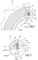
- Figure 1 shows a perspective view of a portion of an embodiment the mold jaw half 10 for a for producing cross-ribbed pipes provided corrugator.
- the mold jaw half 10 has two from each other spaced end faces 12 provided in a common plane are. In Figure 1, only one of these end surfaces 12 is shown.
- the Forming jaw half 10 also has a semi-cylindrical base 14, extending between the two end faces 12, i. these together combines.
- the semi-cylindrical base 14 of the mold jaw half 10 is with Comb 16 and grooves 18 formed in the axial direction of the Alternate mold half 10. At the combs 16 are insert form elements 20 attached. In the grooves 18 are second insert-form elements 22 attached.
- the insert-form elements 20 are provided with a convex cross-sectional edge contour 24 and the insert-form elements 22 are with a concave cross-section edge contour 26 is formed.
- the combs 16 and the Gulls 18 of the semi-cylindrical base 14 of the mold jaw half 10 and the convex cross-sectional edge contour 24 of the insert-form elements 20 and the Concave cross-sectional edge contour 26 of the insert-form elements 22 are such designed that the cross-sectional edge contours 24 and 26 to each other directly and directly steplessly adjoin.
- the edge contours 24 and 26 of the insert-form elements 20 and 22 is the outer surface of the manufactured Transverse finned tube determined.
- the insert-form elements 20 and 22 are formed with end faces 28 which are diametrically and lie in a common plane.
- the end faces 28 of the Insert-form elements 20 and 22 are aligned with the end faces 12 of Mold jaw half 10 plan, i. they span with the end faces 12 a common level up.
- Each of the two end faces 12 of the mold jaw half 10 is one of the number Insert mold elements 20 and 22 corresponding number of first recesses 30 formed on the semi-cylindrical base 14 of the Forming half 10 adjacent.
- the two end faces 28 of the respective Insert molding element 20, 22 are formed with second recesses 32, the adjacent to the corresponding end face 12 of the mold jaw half 10 are provided so that the first and the second recesses 30 and 32nd each form a common recess, which is for receiving a Fixing element 34 is used.
- the fixing elements 34 are for example platelet-shaped with a stepped through hole 36 formed.
- the respective through hole 36 is in an associated threaded blind hole 38 in the Formbackenhzier 10 screwed a screw 40 to the respective Fixing element 34 in the first recess 30 to fix and the associated Insert molding 20 or 22 with the mold jaw half 10 fixed and such too connect that the end faces 12 of the mold jaw half 10 and the end faces 28 of the insert-form elements 20, 22 flush with each other, as from the Figures 2 and 3 is clearly visible.
- the fixing elements 34 are such dimensioned so that their face 42 with the end faces 12 and 28 plan flees.
- FIG. 4 illustrates sections of a shaping jaw half 10 with a section semi-cylindrical base 14, which - as in the embodiment according to Figure 1 - Combs 16 and grooves 18, wherein at the crests 16 insert form elements 20 and in the gutters 18 insert form elements 22 - Training according to Figure 1 according to - are provided, whose cross-sectional edge contours 24 and 26 directly and immediately adjacent to each other.
- the figure 4 illustrates in particular vacuum slots 44, which in the insert-form elements 22 are adapted to in the manufacture of the respective Transverse ribbed tube, the extruded tube material to the concave cross-sectional edge contour 26 of the insert form elements 22 to be fitted.
- Figure 4 also illustrates that the insert-form elements 20 and 22 each on the back, i. at its from the cross-sectional edge contour 24, 26 radially opposite side are formed with a fastening member 48.
- the fastening members 48 with a trapezoidal Cross section formed in the manner of a dovetail guide.
- the combs 16 and grooves 18 having semi-cylindrical base 14 of the Formbackenhcan 10 is cross-sectionally with the fastening members 48 corresponding mounting grooves 50 formed.
- FIGS. 1 to 3 and in FIG. 4 respectively the same reference numerals.
- Figure 5 differs from Figure 4 only in that the insert-form elements 20 and 22 by means of the fixing elements 34 at the semi-cylindrical base 14 of the mold jaw half 10 immovable attached, i. fixed, are.
- the same details are in Figure 5 with the same Reference numerals as in Figures 1 to 4, so that it is unnecessary, in Connection to Figure 5 all these details in detail again describe.
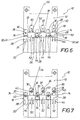
- Figures 6 and 7 show an embodiment of the mold jaw half 10 without Fixing elements (see Figure 6) and with fixing elements 34 (see Figure 7), wherein the semi-cylindrical base 14 of the mold jaw half 10 - like the Formations according to Figures 1 to 5 - with axially alternating Comb 16 and grooves 18 is formed.
- the embodiment according to the Figures 6 and 7, however, is only on a comb 16 an insert-form element 20 with a convex cross-sectional edge contour 24 attached, while the remaining Combs 16 and grooves 18 are combined with insert mold elements 52 and 54, by a smooth surface 56 of the mold jaw half 10 and thus a correspondingly smooth outer surface of the transverse rib tube to be produced is realized.
- Figures 4 and 5 and 6 and 7 are intended to serve in particular clarify that the mold jaw half 10 as desired with arbitrary Insert molding elements 20, 22, 52, 54 may be combined to form transverse ribbed pipes to realize with the respective desired outer surface.
- the respective ones Insert molding elements 20, 22, 52, 54 may also be desired by corresponding other form elements are replaced.
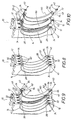
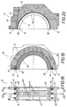
- FIGS. 8 and 9 show, in a three-dimensional view, a mold jaw half 10, in which the semi-cylindrical base 14 is not with ridges and grooves but simply semi-cylindrical with axially spaced apart grooves 58th is formed, wherein each groove 58 is associated with an insert-form element 60.
- the respective insert-shaped element 60 has axially centrally a convex cross-section rib edge contour 62 on, on both sides in each case half a concave Cross-section gutter edge contour 64 connects.
- each insert-form element 60 is back with a Fastening member 48 is formed, which extends in the circumferential direction along the associated insert molding element 60 extends and that to the respective End face 28 adjacent to a second recess 32 (see, for example Figures 2 and 3) is formed.
- a mold jaw half 10 is shown in perspective, which differs from the embodiment according to Figures 8 and 9 in particular by distinguishes between insert elements 60, of which the right shown spaced from the mold jaw half 10, i. in a Exploded exploded view, a half-ring-shaped element 66 is provided is. While with mold jaw halves 10 according to the figures 8 and 9 in a known Corrugator transverse rib pipes with wave troughs and wave crests be realized, in which the wave crests and the troughs axially have at least approximately the same dimensions, is with Molded jaw halves 10 according to FIG. 10 realize a transverse ribbed tube in which the Wave crests are long axially compared to the axial length of the wave troughs.
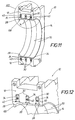
- FIGS. 11 and 12 are intended to form the shaping jaw half 10 illustrate, with the semi-cylindrical base 14 between the two End faces 12 semi-cylindrical with axially spaced apart grooves 58th - Similar to the embodiments according to Figures 8, 9 and 10 - designed are.
- At the semi-cylindrical base 14 are by means of fixing elements 34 or screws 30 insert-form elements 68, 70 fixed to the realization a transverse finned tube - similar to the embodiment of Figure 7 - suitable and are provided.
- Figures 13 and 14 illustrate a mold jaw half 10, similar to the mold jaw half is formed according to Figure 1, wherein the in the gutters 18th the semi-cylindrical base 14 of the mold jaw half 10 fixed second Insert molding elements 22 are formed with vacuum slots 44.
- FIGS. 13 and 14 The same details are shown in FIGS. 13 and 14 with the same reference numerals as indicated in Figures 1 to 12, so that it is unnecessary, in conjunction with Figures 13 and 14 to describe all the details again in detail.
- FIG. 15 shows an end view of a shaping jaw half 10 - similar to the one in FIG Figures 8, 9, 10 and 11 and 12 drawn embodiments of Formbackenhucc 10 -, wherein the semi-cylindrical base 14th semi-cylindrical with axially spaced apart grooves 58 is formed.
- the insert form elements 60 provided fastening members 48 with easy designed a rectangular cross-section.
- the Mounting grooves 50 with a rectangular clear cross-section designed so that it is easy and time-saving, the insert-form elements Do not thread 60 in the circumferential direction in the mold jaw half 10 to have, but the insert-form elements 60 simply from the side in the To set mold jaw half 10. Thereafter, the insert form elements 60 with the aid of fixing elements 34 in the mold jaw half 10 with Help fixed by screws 40.
- the insert-form elements 60 are with Vacuum slots 44 formed.
- FIG. 16 shows a section along the section line XVI-XVI in FIG. 15 the mold jaw half 10 and by an integral with this insert-form element 60 and by the two the corresponding insert-form element 60 fixing fixing elements 34.
- FIG. 17 shows the detail XVII in FIG. 16. The same details are also in the figures 15 to 17 with the same Reference numerals as indicated in Figures 1 to 14.
- FIG. 18 shows a mold jaw half 10 similar to that in FIG. 15 in the drawing illustrated mold jaw half, wherein the insert-form elements 60, however, with Vacuum slots 44 are formed, which extend along the entire Extending the circumferential extent of the respective insert-form element 60, such as in particular also from Figure 20 can be seen.
- the vacuum slots 44 are with the formed in the mold jaw half 10 vacuum channel system 46th fluidically connected, which has already been mentioned above.
- the Vacuum channel system 46 has a first channel portion 72 which is provided with a (not shown) vacuum source is connectable and from one of the End surfaces 12 of the mold jaw half 10 opens to the to connect together belonging mold jaw halves 10 with the vacuum source.
- the first channel section 72 is provided with at least one second channel section 74 fluidly connected, which opens into the vacuum slots 44. Extend the vacuum slots 44 over the entire circumference of the respective insert form element 60, then a single second Channel section 74 be sufficient.
Landscapes
- Engineering & Computer Science (AREA)
- Mechanical Engineering (AREA)
- Manufacturing & Machinery (AREA)
- Moulds For Moulding Plastics Or The Like (AREA)
- Mutual Connection Of Rods And Tubes (AREA)
- Shaping Of Tube Ends By Bending Or Straightening (AREA)
- Drilling And Boring (AREA)
- Ropes Or Cables (AREA)
- Manufacturing Of Tubular Articles Or Embedded Moulded Articles (AREA)
- Rod-Shaped Construction Members (AREA)
Description
- Figur 1
- in einer perspektivischen Ansicht einen Abschnitt einer ersten Ausbildung der Formbackenhälfte zur Herstellung eines Querrippenrohres,
- Figur 2
- einen Querschnitt durch den Abschnitt der Formbackenhälfte gemäß Figur 1,
- Figur 3
- das Detail III in Figur 2 in einem größeren Maßstab,
- Figur 4
- eine Vorderansicht der Formbackenhälfte gemäß Figur 1 in Blickrichtung des Pfeiles IV - ohne die die Einsatzform-Elemente an der Formbackenhälfte unbeweglich fixierenden Fixierelemente,
- Figur 5
- eine der Figur 4 entsprechende Vorderansicht mit den Fixierelementen zum Fixieren der Einsatz-Formelemente an der Formbackenhälfte,
- Figur 6
- eine der Figur 4 prinzipiell ähnliche Vorderansicht einer anderen Ausführungsform der Formbackenhälfte mit Einsatz-Formelementen zur Realisierung eines Querrippenrohres mit Querrinnen, die im Vergleich zum axialen Abstand benachbarter Querrinnen eine kleine axiale lichte Weite besitzen,
- Figur 7
- die Formbackenhälfte gemäß Figur 6 - ähnlich wie die Formbackenhälfte gemäß Figur 5, wobei auch die die Einsatz-Formelemente an der Formbackenhälfte fixierenden Fixierelemente dargestellt sind,
- Figur 8
- eine räumliche Darstellung einer Ausbildung der Formbackenhälfte mit Einsatz-Formelementen, wobei die halbzylinderartige Grundflächeder Formbackenhälfte einfach halbzylindrisch mit voneinander axial beabstandeten Rillen ausgebildet ist,
- Figur 9
- die Formbackenhälfte gemäß Figur 8, wobei ein Einsatz-Formelement von der Formbackenhälfte räumlich beabstandet, d.h. in einer Explosionsdarstellung gezeichnet ist,
- Figur 10
- eine der Figur 9 prinzipiell ähnliche perspektivische Explosionsdarstellung einer Ausbildung der Formbackenhälfte, wobei zwischen zwei axial äußeren Einsatz-Formelementen mit einer Rippenrandkontur ein Einsatz-Formelement vorgesehen ist, das als Halbring-Formelement - ohne Rippenkontur - gestaltet ist,
- Figur 11
- eine Formbackenhälfte zur Herstellung eines Querrippenrohresähnlich der in Figur 7 abschnittweise dargestellten Formbackenhälfte, wobei die halbzylinderartige Grundfläche der Formbackenhälfte jedoch - wie bei den Ausbildungen gemäß den Figuren 8 bis 10 - einfach halbzylindrisch mit voneinander axial beabstandeten Rillen ausgebildet ist,
- Figur 12
- das Detail XII gemäß Figur 11 in einem größeren Maßstab,
- Figur 13
- eine räumliche Darstellung einer Formbackenhälfte ähnlich der in Figur 1 gezeichneten Formbackenhälfte, wobei die Einsatz-Formelemente mit Vakuumschlitzen ausgebildet sind,
- Figur 14
- eine Darstellung des Details XIV in Figur 13 in einem größeren Maßstab,
- Figur 15
- eine Vorderansicht einer Formbackenhälfte ähnlich den Formbackenhälften gemäß den Figuren 8 bis 10, wobei die Einsatz-Formelemente mit Vakuumschlitzen ausgebildet sind,
- Figur 16
- einen Schnitt entlang der Schnittlinie XVI-XVI in Figur 15 durch die Formbackenhälfte mit ihren Einsatz-Formelementen und den die Einsatz-Formelemente in der Formbackenhälfte fixierenden Fixierelementen,
- Figur 17
- das Detail XVII gemäß Figur 16 in einem größeren Maßstab,
- Figur 18
- eine der Figur 15 ähnliche Darstellung einer Ausbildung der Formbackenhälfte, wobei die Vakuumschlitze sich jedoch entlang der gesamten Umfangserstreckung der Einsatz-Formelemente erstrecken,
- Figur 19
- einen Schnitt entlang der Schnittlinie XIX-XIX in Figur 18, und
- Figur 20
- einen Schnitt entlang der Schnittlinie XX-XX in Figur 18.
Claims (17)
- Formbackenhälfte für einen Corrugator zum Herstellen von Querrippenrohren, wobei die Formbackenhälfte (10) zwei voneinander beabstandete, in einer gemeinsamen Ebene angeordnete Stirnflächen (12) und eine die beiden Stirnflächen (12) verbindende halbzylinderartige Grundfläche (14) aufweist, an der die Außenoberfläche des Querrippenrohres bestimmende halbkreisbogenförmige Einsatz-Formelemente (20, 22; 52, 54; 60; 66; 68, 70) loslösbar angebracht sind, die jeweils zwei sich diametral gegenüberliegende Formelement-Stirnflächen (28) aufweisen, die mit den Stirnflächen (12) der Formbackenhälfte (10) plan fluchten, wobei jede der beiden Stirnflächen (12) der Formbackenhälfte (10) an die halbzylinderartige Grundfläche (14) angrenzend mit einer der Anzahl Einsatz-Formelemente entsprechenden Anzahl ersten Aussparungen (30) und die beiden Formelement-Stirnflächen (28) des jeweiligen Einsatz-Formelementes an die beiden Stirnflächen (12) der Formbackenhälfte (10) angrenzend mit jeweils einer zweiten Aussparung (32) ausgebildet sind, wobei sich zwischen der jeweiligen ersten Aussparung (30) und der zugehörigen zweiten Aussparung (32), zum Festlegen des jeweiligen Einsatz-Formelementes an der Formbackenhälfte (10), ein Fixierelement (34) erstreckt.
- Formbackenhälfte nach Anspruch 1,
dadurch gekennzeichnet, daß eines oder mehrere der Einsatzformelemente konvexe Querschnittsrandkontur aufweist bzw. aufweisen. - Formbackenhälfte nach Anspruch 1 oder 2,
dadurch gekennzeichnet, daß eines oder mehrere der Einsatzformelemente konkave Querschnittsrandkonturen aufweist bzw. aufweisen. - Formbackenhälfte nach einem der vorangehenden Ansprüche,
dadurch gekennzeichnet, daß eines oder mehrere der Einsatzformelemente (60) axial mittig eine konvexe Querschnitts-Rippenrandkontur (62) und an diese beidseitig anschließend jeweils eine halbe konkave Querschnitts-Rinnenrandkontur (64) aufweist. - Formbackenhälfte nach einem der vorangehenden Ansprüche,
dadurch gekennzeichnet, daß eines oder mehrere der Einsatzformelemente als Halbringformelemente mit zylindrischer Querschnittsrandkontur ausgebildet ist bzw. sind. - Formbackenhälfte nach einem der vorangehenden Ansprüche,
dadurch gekennzeichnet, daß identisch ausgebildete Einsatzformelemente in axialer Richtung nebeneinander angeordnet sind. - Formbackenhälfte nach einem der vorangehenden Ansprüche,
dadurch gekennzeichnet, daß unterschiedlich ausgebildete Einsatzformelemente in axialer Richtung nebeneinander angeordnet sind. - Formbackenhälfte nach einem der vorangehenden Ansprüche,
dadurch gekennzeichnet, daß die Querschnittsrandkonturen zweier benachbarter Einsatzformelemente aneinander direkt und unmittelbar angrenzen, vorzugsweise derart, daß einander benachbarte Einsatzformelemente allein die Außenoberfläche des herzustellenden Querrippenrohres bestimmen. - Formbackenhälfte nach einem der vorangehenden Ansprüche,
dadurch gekennzeichnet, daß die Querschnittsrandkonturen zweier benachbarter Einsatzformelemente einen Abstand zueinander aufweisen, der durch einen entsprechenden Abschnitt der Formbackenhälfte überbrückt ist, vorzugsweise derart, daß benachbarte Einsatzformelemente gemeinsam mit diesem überbrückenden Abschnitt der Formbackenhälfte die Außenoberfläche des herzustellenden Querrippenrohres bestimmen. - Formbackenhälfte nach einem der vorangehenden Ansprüche,
dadurch gekennzeichnet, daß die halbzylinderartige Grundfläche voneinander axial beabstandete Rillen aufweist, wobei jeder Rille jeweils ein separates Einsatzformelement (20, 22; 52, 54; 60; 66; 68, 70) lösbar zugeordnet ist, wobei die Querschnittsrandkontur der Einsatzformelemente identisch oder unterschiedlich ausgebildet ist. - Formbackenhälfte nach einem der vorangehenden Ansprüche,
dadurch gekennzeichnet, daß die halbzylinderartige Grundfläche (14) der Formbackenhälfte (10) mit sich in axialer Richtung abwechselnden Kämmen (16) und Rinnen (18) ausgebildet ist, wobei an mindestens einem der Kämme (16) ein Einsatzformelement (20) mit einer konvexen Querschnittsrandkontur (24) angebracht ist. - Formbackenhälfte nach Anspruch 11,
dadurch gekennzeichnet, daß jeweils an den Kämmen (16) Einsatzformelemente (20) mit einer konvexen Querschnittsrandkontur (24) und in den Rinnen (18) Einsatzformelemente (22) mit einer konkaven Querschnittsrandkontur (26) oder Halbringformelemente mit zylindrischer Querschnittsrandkontur angebracht sind. - Formbackenelemente nach einem der vorangehenden Ansprüche,
dadurch gekennzeichnet, daß zwischen Einsatzformelementen (60), die eine konvexe Querschnitts-Rippenrandkontur (62) und an diese beidseitig anschließend jeweils eine halbe konkave Querschnitts-Rinnenrandkontur (64) aufweisen, mindestens ein Halbring-Formelement (66) angeordnet ist, wobei das mindestens eine Halbringformelement (66) an das benachbarte Einsatzformelement (60) stufenlos anschließt. - Formbackenhälfte nach einem der vorangehenden Ansprüche,
dadurch gekennzeichnet, daß jedes Einsatzformelement (20, 22; 52, 54; 60, 66; 68, 70) rückseitig mit einem Befestigungsorgan (48) ausgebildet ist, das in eine daran querschnittsmäßig angepaßte Befestigungsrinne (50) in der halbzylinderartigen Grundfläche (14) der Formbackenhälfte (10) eingepaßt ist. - Formbackenhälfte nach Anspruch 14,
dadurch gekennzeichnet, daß das Befestigungsorgan (48) und die daran formmäßig angepaßte Befestigungsrinne (50) mit einem einfach rechteckförmigen Querschnittsprofil ausgebildet sind oder hinterschnitten, vorzugsweise schwalbenschwanzförmig komplementär ausgebildet sind. - Formbackenhälfte nach einem der vorangehenden Ansprüche,
dadurch gekennzeichnet, daß die Einsatzformelemente (22; 60) mit Vakuumschlitzen (44) und daß die Formbackenhälfte (10) mit einem Vakuumkanalsystem (46) ausgebildet sind. - Formbackenhälfte nach Anspruch 16,
dadurch gekennzeichnet, daß das Vakuumkanalsystem (46) mindestens einen aus einer der Stirnflächen (12) der Formbackenhälfte (10) ausmündenden, mit einer Vakuumquelle verbindbaren ersten Kanalabschnitt (72) und mindestens einen mit diesem verbundenen zweiten Kanalabschnitt (74) aufweist, der in die Vakuumschlitze (44) ausmündet.
Applications Claiming Priority (3)
| Application Number | Priority Date | Filing Date | Title |
|---|---|---|---|
| DE10148294 | 2001-09-29 | ||
| DE10148294A DE10148294C1 (de) | 2001-09-29 | 2001-09-29 | Formbackenhälfte für einen Corrugator zum Herstellen von Querrippenrohren |
| PCT/DE2002/002949 WO2003031155A1 (de) | 2001-09-29 | 2002-08-10 | Formbackenhälfte für einen corrugator zum herstellen von querrippenrohren |
Publications (2)
| Publication Number | Publication Date |
|---|---|
| EP1429906A1 EP1429906A1 (de) | 2004-06-23 |
| EP1429906B1 true EP1429906B1 (de) | 2005-04-20 |
Family
ID=7700904
Family Applications (1)
| Application Number | Title | Priority Date | Filing Date |
|---|---|---|---|
| EP02758141A Expired - Lifetime EP1429906B1 (de) | 2001-09-29 | 2002-08-10 | Formbackenhälfte für einen corrugator zum herstellen von querrippenrohren |
Country Status (9)
| Country | Link |
|---|---|
| US (1) | US7306448B2 (de) |
| EP (1) | EP1429906B1 (de) |
| CN (1) | CN1263592C (de) |
| AT (1) | ATE293532T1 (de) |
| CA (1) | CA2462141C (de) |
| DE (2) | DE10148294C1 (de) |
| ES (1) | ES2239248T3 (de) |
| PT (1) | PT1429906E (de) |
| WO (1) | WO2003031155A1 (de) |
Families Citing this family (29)
| Publication number | Priority date | Publication date | Assignee | Title |
|---|---|---|---|---|
| CA2411881C (en) * | 2002-11-15 | 2009-09-15 | Manfred A. A. Lupke | Molding apparatus with mold blocks having face adjustment |
| US7338626B1 (en) | 2002-12-14 | 2008-03-04 | Federal Mogul World Wide, Inc. | High cavitation, low tonnage rubber mold machine and method |
| DE102004040019B4 (de) * | 2004-08-18 | 2011-06-22 | Drossbach GmbH & Co. KG, 86641 | Vorrichtung zur Herstellung von Wellrohren |
| US7980030B2 (en) * | 2007-07-11 | 2011-07-19 | Daewon Electric Co. Ltd. | C-type underbracing having enlarged end portions for installing on utility pole |
| KR100772919B1 (ko) * | 2007-07-11 | 2007-11-05 | 대원전기 주식회사 | 양끝 올림부를 갖는 건주공사용 c형 전주근가 |
| ES2337973B8 (es) | 2008-05-16 | 2011-07-21 | Proyecto De Biomedicina Cima, S.L. | Adenovirus auxiliares auto-inactivantes para la produccion de adenovirus recombinantes de alta capacidad. |
| ES2330826B1 (es) | 2008-06-04 | 2010-07-26 | Proyecto De Biomedicina Cima, S.L. | Sistema para empaquetamiento de adenovirus de alta capacidad. |
| DE102008027102B4 (de) | 2008-06-06 | 2011-11-17 | Unicor Gmbh | Doppelwand-Wellrohr und Formbacken für eine Vorrichtung zur Herstellung eines derartigen Doppelwand-Wellrohres |
| US8808610B2 (en) * | 2009-04-01 | 2014-08-19 | Patrick E. Scharf | Systems and methods for cooling moving molds |
| FR2948313B1 (fr) * | 2009-07-23 | 2015-05-15 | Sidel Participations | Systeme d'assemblage pour unite de moulage et unite de moulage comportant un tel systeme |
| JP5609423B2 (ja) * | 2009-09-30 | 2014-10-22 | キョーラク株式会社 | 空調ダクトの製造方法、及び空調ダクト |
| WO2012001196A2 (es) | 2010-06-28 | 2012-01-05 | Proyecto De Biomedicina Cima, S.L. | Vectores alfavirales y usos de los mismos para la expresión de genes heterólogos |
| EP2407534A1 (de) | 2010-07-14 | 2012-01-18 | Neo Virnatech, S.L. | Verfahren und Reagenzien zum Erhalt von transkriptionell aktiven virusähnlichen Artikeln und rekombinante Virionen |
| WO2013113755A1 (en) | 2012-01-30 | 2013-08-08 | Fundació Institut D'investigació Biomèdica De Bellvitge (Idibell) | Reagents and methods for the treatment of diseases based on the inhibition of calcineurin - nfat signalling pathway |
| CN103057086A (zh) * | 2012-12-14 | 2013-04-24 | 大连三垒机器股份有限公司 | 方形单壁波纹管成型模具 |
| ES2523016B1 (es) | 2013-05-20 | 2015-09-09 | 3P Biopharmaceuticals | Vectores alfavirales y líneas celulares para la producción de proteínas recombinantes |
| EP2878674A1 (de) | 2013-11-28 | 2015-06-03 | Fundación Centro Nacional de Investigaciones Cardiovasculares Carlos III (CNIC) | Stabile Episomen auf Basis von nichtintegrativen lentiviralen Vektoren |
| EP3089755A1 (de) | 2014-01-03 | 2016-11-09 | Fundacion Biofisica Bizkaia | Vlps, verfahren zu deren gewinnung und anwendungen davon |
| JP1527322S (de) * | 2014-11-26 | 2017-06-05 | ||
| JP1525573S (de) * | 2014-11-26 | 2017-05-22 | ||
| JP1525574S (de) * | 2014-11-26 | 2017-05-22 | ||
| JP1525571S (de) * | 2014-11-26 | 2017-05-22 | ||
| JP1525570S (de) * | 2014-11-26 | 2017-05-22 | ||
| CN104723579B (zh) * | 2015-04-13 | 2017-03-22 | 哈尔滨工业大学 | 一种全复合材料波纹夹层圆柱壳的组合模具 |
| JP6770976B2 (ja) | 2015-05-04 | 2020-10-21 | リテック システムズ エルエルシー | テーパ状ねじ山付きプラーヘッド |
| USD764554S1 (en) * | 2015-05-05 | 2016-08-23 | Retech Systems Llc | Threaded tapered mold |
| JP7417525B2 (ja) | 2017-11-30 | 2024-01-18 | コーニング インコーポレイテッド | 二軸配向された熱可塑性ピペットおよび二軸配向された熱可塑性ピペットを成形するための方法および装置 |
| DE102018217798A1 (de) * | 2018-10-17 | 2020-04-23 | Fränkische Industrial Pipes GmbH & Co. KG | Variable Formbacke |
| CN117484826B (zh) * | 2023-12-15 | 2024-05-24 | 东莞市永晟电线科技股份有限公司 | 铜排抽真空挤塑装置及工艺 |
Family Cites Families (24)
| Publication number | Priority date | Publication date | Assignee | Title |
|---|---|---|---|---|
| US3380121A (en) * | 1965-07-30 | 1968-04-30 | American Can Co | Mold with replaceable inserts |
| US3430292A (en) * | 1967-04-28 | 1969-03-04 | Acme Hamilton Mfg Corp | Apparatus for the continuous formation of tubular articles |
| DE2061027C3 (de) * | 1970-12-11 | 1982-03-04 | Wilhelm 8730 Bad Kissingen Hegler | Vorrichtung zum Anbringen einer Querprofilierung an einem Rohr aus thermoplastischem Kunststoff |
| US3784346A (en) * | 1972-06-12 | 1974-01-08 | Plastic Tubing | Converted corrugated pipe molding machine |
| US3864446A (en) | 1972-06-12 | 1975-02-04 | Plastic Tubing | Method of converting corrugated pipe molding machine |
| US3859025A (en) * | 1972-07-13 | 1975-01-07 | Ernest J Maroschak | Apparatus for making corrugated plastic pipes with integral coupler collar |
| FR2360405A1 (fr) * | 1976-05-10 | 1978-03-03 | Verges Paul | Dispositif de moules flexibles utilises dans la fabrication d'objets creux a partir d'une paraison tubulaire en matiere thermo-plastique |
| CA1083766A (en) * | 1977-02-07 | 1980-08-19 | Gerd P.H. Lupke | Apparatus for producing thermoplastic tubing |
| DE3120480A1 (de) * | 1981-05-22 | 1982-12-09 | Hegler, Wilhelm, 8730 Bad Kissingen | Vorrichtung zur herstellung von kunststoffrohren mit querrillen |
| US4504206A (en) * | 1982-01-21 | 1985-03-12 | Lupke Manfred Arno Alfred | Chainless mold drive for a corrugator or the like |
| US5059109A (en) * | 1989-12-26 | 1991-10-22 | Cullom Machine Tool & Die, Inc. | Corrugated mold block |
| US5516482A (en) * | 1991-06-14 | 1996-05-14 | Corma Inc. | Travelling mold tunnel apparatus for smooth walled pipe |
| GB9212684D0 (en) * | 1992-06-15 | 1992-07-29 | Lupke Manfred Arno Alfred | A method and apparatus for forming profiled tubes |
| DE4408064C1 (de) * | 1994-03-05 | 1995-09-07 | Lueers Heinrich | Einrichtung zur Kalibrierung des Außendurchmessers eines kontinuierlich extrudierten Rohres |
| US5582849A (en) * | 1994-05-06 | 1996-12-10 | Lupke; Manfred A. A. | Travelling mold with mold block carriers |
| DE19702547B4 (de) | 1996-02-03 | 2008-02-14 | Volkswagen Ag | Kolben-Pleuelverbindung einer Hubkolben-Brennkraftmaschine und Verfahren zur Montage einer solchen Verbindung |
| DE19702637C1 (de) | 1997-01-25 | 1998-08-13 | Unicor Rohrsysteme Gmbh | Vorrichtung zum Herstellen von Querrippen-Rohren |
| DE19702645C1 (de) | 1997-01-25 | 1998-06-10 | Unicor Rohrsysteme Gmbh | Vorrichtung zum Herstellen von Querrippen-Rohren |
| DE19914974C2 (de) | 1999-04-01 | 2001-11-29 | Kirchner Fraenk Rohr | Wechselcorrugator |
| DE19916641C2 (de) | 1999-04-14 | 2002-09-05 | Unicor Rohrsysteme Gmbh | Vorrichtung zur Herstellung eines in seiner Längsrichtung öffenbaren und wiederverschließbaren Wellrohres |
| DE19922726A1 (de) | 1999-05-18 | 2000-11-23 | Ralph Peter Hegler | Vorrichtung zur Herstellung von Kunststoff-Wellrohren |
| DE19946571C1 (de) * | 1999-09-29 | 2000-10-05 | Unicor Rohrsysteme Gmbh | Vorrichtung zum Herstellen von Rohren mit querprofilierter Wandung |
| DE20009030U1 (de) * | 2000-02-23 | 2000-08-24 | Lupke, Manfred Arno Alfred, Thornhill, Ontario | Formblockabschnitt mit einstellbarer Formfläche |
| CA2411881C (en) * | 2002-11-15 | 2009-09-15 | Manfred A. A. Lupke | Molding apparatus with mold blocks having face adjustment |
-
2001
- 2001-09-29 DE DE10148294A patent/DE10148294C1/de not_active Expired - Fee Related
-
2002
- 2002-08-10 WO PCT/DE2002/002949 patent/WO2003031155A1/de not_active Ceased
- 2002-08-10 AT AT02758141T patent/ATE293532T1/de not_active IP Right Cessation
- 2002-08-10 DE DE50202860T patent/DE50202860D1/de not_active Expired - Lifetime
- 2002-08-10 EP EP02758141A patent/EP1429906B1/de not_active Expired - Lifetime
- 2002-08-10 PT PT02758141T patent/PT1429906E/pt unknown
- 2002-08-10 ES ES02758141T patent/ES2239248T3/es not_active Expired - Lifetime
- 2002-08-10 CA CA2462141A patent/CA2462141C/en not_active Expired - Lifetime
- 2002-08-10 CN CNB028190831A patent/CN1263592C/zh not_active Expired - Fee Related
- 2002-08-10 US US10/491,066 patent/US7306448B2/en not_active Expired - Fee Related
Also Published As
| Publication number | Publication date |
|---|---|
| ATE293532T1 (de) | 2005-05-15 |
| CN1263592C (zh) | 2006-07-12 |
| PT1429906E (pt) | 2005-06-30 |
| CN1561283A (zh) | 2005-01-05 |
| DE50202860D1 (de) | 2005-05-25 |
| US20040241266A1 (en) | 2004-12-02 |
| CA2462141A1 (en) | 2003-04-17 |
| ES2239248T3 (es) | 2005-09-16 |
| CA2462141C (en) | 2010-05-25 |
| EP1429906A1 (de) | 2004-06-23 |
| DE10148294C1 (de) | 2003-01-16 |
| US7306448B2 (en) | 2007-12-11 |
| WO2003031155A1 (de) | 2003-04-17 |
Similar Documents
| Publication | Publication Date | Title |
|---|---|---|
| EP1429906B1 (de) | Formbackenhälfte für einen corrugator zum herstellen von querrippenrohren | |
| EP0966624B1 (de) | Faltbares schutzelement für leitungen | |
| EP0385465B2 (de) | Verfahren zur Herstellung eines Abwasserrohrs aus Kunststoff | |
| EP1959208B1 (de) | Luftverteiler, Luftverteiler-System sowie Luftverteilungs-System | |
| DE3050690C2 (de) | Wärmetauscher mit einer Wärmetauschermatte aus elastomerem Material | |
| EP0890770B1 (de) | Verbundrohr mit angeformter Rohr-Muffe und Verfahren zu dessen Herstellung | |
| DE69205000T2 (de) | Verfahren zum herstellen einer zahnärztlichen absaugeinrichtung. | |
| EP4435307A2 (de) | Kunststoffrohr und kunststoffmuffe zum verbinden mit einem derartigen kunststoffrohr | |
| DE102015107746B4 (de) | Abgasrohr, System sowie Verfahren zum Herstellen eines Abgasrohrabschnittes | |
| EP0734062A2 (de) | Kühlkörper für Halbleiterbauelemente od. dgl. | |
| EP1360061B1 (de) | Vorrichtung zur herstellung von kunststoffrohren | |
| DE69900677T2 (de) | Formwerkzeug mit luftströmungseinstellung | |
| DE10006380A1 (de) | Vorrichtung zur Herstellung von profilierten Kunststoff-Rohren | |
| EP3086012B1 (de) | Abgasrohr, system sowie verfahren zum herstellen eines abgasrohrabschnittes | |
| DE69121410T2 (de) | Maschine mit wanderndem formtunnel zur herstellung glattwandiger rohre | |
| EP1302301A1 (de) | Vorrichtung zur Herstellung von gewellten Kunststoff-Rohren | |
| EP0948108A2 (de) | Wellrohr mit Fuss | |
| DE19638714A1 (de) | Mattenartiger Wärmetauscher für Kühl- und/oder Heizzwecke | |
| DE20116058U1 (de) | Formbackenhälfte für einen Corrugator zum Herstellen von Querrippenrohren | |
| EP4434716A1 (de) | Kunststoffrohr und vorrichtung zur kontinuierlichen herstellung eines rohrgrundkörpers für ein derartiges kunststoffrohr | |
| EP1216126B1 (de) | Vorrichtung zum herstellen von rohren mit querprofilierter wandung | |
| EP1553363B1 (de) | Heiz- bzw. Kühlkörper-Verteileranordnung | |
| DE3016628C2 (de) | Energieleitungsträger | |
| DE1572485A1 (de) | Schalldaempfer | |
| EP2049318B1 (de) | Spritzkopf für einen corrugator zur herstellung von kunststoffrohren |
Legal Events
| Date | Code | Title | Description |
|---|---|---|---|
| PUAI | Public reference made under article 153(3) epc to a published international application that has entered the european phase |
Free format text: ORIGINAL CODE: 0009012 |
|
| 17P | Request for examination filed |
Effective date: 20040304 |
|
| AK | Designated contracting states |
Kind code of ref document: A1 Designated state(s): AT BE BG CH CY CZ DE DK EE ES FI FR GB GR IE IT LI LU MC NL PT SE SK TR |
|
| AX | Request for extension of the european patent |
Extension state: AL LT LV MK RO SI |
|
| GRAP | Despatch of communication of intention to grant a patent |
Free format text: ORIGINAL CODE: EPIDOSNIGR1 |
|
| GRAS | Grant fee paid |
Free format text: ORIGINAL CODE: EPIDOSNIGR3 |
|
| GRAA | (expected) grant |
Free format text: ORIGINAL CODE: 0009210 |
|
| AK | Designated contracting states |
Kind code of ref document: B1 Designated state(s): AT BE BG CH CY CZ DE DK EE ES FI FR GB GR IE IT LI LU MC NL PT SE SK TR |
|
| PG25 | Lapsed in a contracting state [announced via postgrant information from national office to epo] |
Ref country code: SK Free format text: LAPSE BECAUSE OF FAILURE TO SUBMIT A TRANSLATION OF THE DESCRIPTION OR TO PAY THE FEE WITHIN THE PRESCRIBED TIME-LIMIT Effective date: 20050420 Ref country code: IE Free format text: LAPSE BECAUSE OF FAILURE TO SUBMIT A TRANSLATION OF THE DESCRIPTION OR TO PAY THE FEE WITHIN THE PRESCRIBED TIME-LIMIT Effective date: 20050420 Ref country code: GB Free format text: LAPSE BECAUSE OF FAILURE TO SUBMIT A TRANSLATION OF THE DESCRIPTION OR TO PAY THE FEE WITHIN THE PRESCRIBED TIME-LIMIT Effective date: 20050420 Ref country code: NL Free format text: LAPSE BECAUSE OF FAILURE TO SUBMIT A TRANSLATION OF THE DESCRIPTION OR TO PAY THE FEE WITHIN THE PRESCRIBED TIME-LIMIT Effective date: 20050420 Ref country code: FI Free format text: LAPSE BECAUSE OF FAILURE TO SUBMIT A TRANSLATION OF THE DESCRIPTION OR TO PAY THE FEE WITHIN THE PRESCRIBED TIME-LIMIT Effective date: 20050420 Ref country code: EE Free format text: LAPSE BECAUSE OF FAILURE TO SUBMIT A TRANSLATION OF THE DESCRIPTION OR TO PAY THE FEE WITHIN THE PRESCRIBED TIME-LIMIT Effective date: 20050420 Ref country code: CZ Free format text: LAPSE BECAUSE OF FAILURE TO SUBMIT A TRANSLATION OF THE DESCRIPTION OR TO PAY THE FEE WITHIN THE PRESCRIBED TIME-LIMIT Effective date: 20050420 |
|
| REG | Reference to a national code |
Ref country code: GB Ref legal event code: FG4D Free format text: NOT ENGLISH |
|
| REG | Reference to a national code |
Ref country code: CH Ref legal event code: EP |
|
| REG | Reference to a national code |
Ref country code: IE Ref legal event code: FG4D Free format text: LANGUAGE OF EP DOCUMENT: GERMAN |
|
| REF | Corresponds to: |
Ref document number: 50202860 Country of ref document: DE Date of ref document: 20050525 Kind code of ref document: P |
|
| REG | Reference to a national code |
Ref country code: PT Ref legal event code: SC4A Free format text: AVAILABILITY OF NATIONAL TRANSLATION Effective date: 20050426 |
|
| PG25 | Lapsed in a contracting state [announced via postgrant information from national office to epo] |
Ref country code: BG Free format text: LAPSE BECAUSE OF FAILURE TO SUBMIT A TRANSLATION OF THE DESCRIPTION OR TO PAY THE FEE WITHIN THE PRESCRIBED TIME-LIMIT Effective date: 20050720 Ref country code: GR Free format text: LAPSE BECAUSE OF FAILURE TO SUBMIT A TRANSLATION OF THE DESCRIPTION OR TO PAY THE FEE WITHIN THE PRESCRIBED TIME-LIMIT Effective date: 20050720 Ref country code: DK Free format text: LAPSE BECAUSE OF FAILURE TO SUBMIT A TRANSLATION OF THE DESCRIPTION OR TO PAY THE FEE WITHIN THE PRESCRIBED TIME-LIMIT Effective date: 20050720 Ref country code: SE Free format text: LAPSE BECAUSE OF FAILURE TO SUBMIT A TRANSLATION OF THE DESCRIPTION OR TO PAY THE FEE WITHIN THE PRESCRIBED TIME-LIMIT Effective date: 20050720 |
|
| PG25 | Lapsed in a contracting state [announced via postgrant information from national office to epo] |
Ref country code: AT Free format text: LAPSE BECAUSE OF NON-PAYMENT OF DUE FEES Effective date: 20050810 Ref country code: CY Free format text: LAPSE BECAUSE OF FAILURE TO SUBMIT A TRANSLATION OF THE DESCRIPTION OR TO PAY THE FEE WITHIN THE PRESCRIBED TIME-LIMIT Effective date: 20050810 Ref country code: LU Free format text: LAPSE BECAUSE OF NON-PAYMENT OF DUE FEES Effective date: 20050810 |
|
| PG25 | Lapsed in a contracting state [announced via postgrant information from national office to epo] |
Ref country code: BE Free format text: LAPSE BECAUSE OF NON-PAYMENT OF DUE FEES Effective date: 20050831 Ref country code: MC Free format text: LAPSE BECAUSE OF NON-PAYMENT OF DUE FEES Effective date: 20050831 |
|
| REG | Reference to a national code |
Ref country code: ES Ref legal event code: FG2A Ref document number: 2239248 Country of ref document: ES Kind code of ref document: T3 |
|
| NLV1 | Nl: lapsed or annulled due to failure to fulfill the requirements of art. 29p and 29m of the patents act | ||
| GBV | Gb: ep patent (uk) treated as always having been void in accordance with gb section 77(7)/1977 [no translation filed] |
Effective date: 20050420 |
|
| REG | Reference to a national code |
Ref country code: IE Ref legal event code: FD4D |
|
| PLBE | No opposition filed within time limit |
Free format text: ORIGINAL CODE: 0009261 |
|
| STAA | Information on the status of an ep patent application or granted ep patent |
Free format text: STATUS: NO OPPOSITION FILED WITHIN TIME LIMIT |
|
| ET | Fr: translation filed | ||
| 26N | No opposition filed |
Effective date: 20060123 |
|
| PG25 | Lapsed in a contracting state [announced via postgrant information from national office to epo] |
Ref country code: CH Free format text: LAPSE BECAUSE OF NON-PAYMENT OF DUE FEES Effective date: 20060831 Ref country code: LI Free format text: LAPSE BECAUSE OF NON-PAYMENT OF DUE FEES Effective date: 20060831 |
|
| REG | Reference to a national code |
Ref country code: CH Ref legal event code: PL |
|
| BERE | Be: lapsed |
Owner name: UNICOR G.M.B.H. RAHN PLASTMASCHINEN Effective date: 20050831 |
|
| REG | Reference to a national code |
Ref country code: FR Ref legal event code: PLFP Year of fee payment: 15 |
|
| REG | Reference to a national code |
Ref country code: FR Ref legal event code: PLFP Year of fee payment: 16 |
|
| REG | Reference to a national code |
Ref country code: FR Ref legal event code: PLFP Year of fee payment: 17 |
|
| REG | Reference to a national code |
Ref country code: DE Ref legal event code: R079 Ref document number: 50202860 Country of ref document: DE Free format text: PREVIOUS MAIN CLASS: B29C0047900000 Ipc: B29C0048900000 |
|
| PGFP | Annual fee paid to national office [announced via postgrant information from national office to epo] |
Ref country code: PT Payment date: 20180730 Year of fee payment: 17 |
|
| PG25 | Lapsed in a contracting state [announced via postgrant information from national office to epo] |
Ref country code: PT Free format text: LAPSE BECAUSE OF NON-PAYMENT OF DUE FEES Effective date: 20200210 |
|
| PGFP | Annual fee paid to national office [announced via postgrant information from national office to epo] |
Ref country code: FR Payment date: 20200827 Year of fee payment: 19 Ref country code: TR Payment date: 20200805 Year of fee payment: 19 Ref country code: DE Payment date: 20200907 Year of fee payment: 19 Ref country code: ES Payment date: 20200917 Year of fee payment: 19 |
|
| PGFP | Annual fee paid to national office [announced via postgrant information from national office to epo] |
Ref country code: IT Payment date: 20200930 Year of fee payment: 19 |
|
| REG | Reference to a national code |
Ref country code: DE Ref legal event code: R119 Ref document number: 50202860 Country of ref document: DE |
|
| PG25 | Lapsed in a contracting state [announced via postgrant information from national office to epo] |
Ref country code: IT Free format text: LAPSE BECAUSE OF NON-PAYMENT OF DUE FEES Effective date: 20210810 Ref country code: FR Free format text: LAPSE BECAUSE OF NON-PAYMENT OF DUE FEES Effective date: 20210831 Ref country code: DE Free format text: LAPSE BECAUSE OF NON-PAYMENT OF DUE FEES Effective date: 20220301 |
|
| REG | Reference to a national code |
Ref country code: ES Ref legal event code: FD2A Effective date: 20220927 |
|
| PG25 | Lapsed in a contracting state [announced via postgrant information from national office to epo] |
Ref country code: ES Free format text: LAPSE BECAUSE OF NON-PAYMENT OF DUE FEES Effective date: 20210811 |