EP1429210A2 - Reinigungsvorrichtung mit einer elektroleitfähigen Reinigungsbürste - Google Patents
Reinigungsvorrichtung mit einer elektroleitfähigen Reinigungsbürste Download PDFInfo
- Publication number
- EP1429210A2 EP1429210A2 EP03022595A EP03022595A EP1429210A2 EP 1429210 A2 EP1429210 A2 EP 1429210A2 EP 03022595 A EP03022595 A EP 03022595A EP 03022595 A EP03022595 A EP 03022595A EP 1429210 A2 EP1429210 A2 EP 1429210A2
- Authority
- EP
- European Patent Office
- Prior art keywords
- brush
- cleaning apparatus
- cleaned
- image
- image forming
- Prior art date
- Legal status (The legal status is an assumption and is not a legal conclusion. Google has not performed a legal analysis and makes no representation as to the accuracy of the status listed.)
- Ceased
Links
- 238000004140 cleaning Methods 0.000 title claims abstract description 62
- 239000002245 particle Substances 0.000 claims abstract description 30
- 239000004020 conductor Substances 0.000 claims abstract description 13
- 238000012546 transfer Methods 0.000 claims description 36
- 238000000034 method Methods 0.000 claims description 22
- 238000006116 polymerization reaction Methods 0.000 claims description 5
- OKTJSMMVPCPJKN-UHFFFAOYSA-N Carbon Chemical compound [C] OKTJSMMVPCPJKN-UHFFFAOYSA-N 0.000 claims description 3
- 229910052799 carbon Inorganic materials 0.000 claims description 3
- 108091008695 photoreceptors Proteins 0.000 description 46
- 230000002093 peripheral effect Effects 0.000 description 15
- 238000007599 discharging Methods 0.000 description 11
- 239000000126 substance Substances 0.000 description 8
- 239000000428 dust Substances 0.000 description 7
- 238000011156 evaluation Methods 0.000 description 5
- 239000000463 material Substances 0.000 description 4
- 239000004677 Nylon Substances 0.000 description 3
- 238000011109 contamination Methods 0.000 description 3
- 229920001778 nylon Polymers 0.000 description 3
- 238000000926 separation method Methods 0.000 description 3
- 238000012360 testing method Methods 0.000 description 3
- 238000007639 printing Methods 0.000 description 2
- 230000002159 abnormal effect Effects 0.000 description 1
- 239000000853 adhesive Substances 0.000 description 1
- 230000001070 adhesive effect Effects 0.000 description 1
- 238000005452 bending Methods 0.000 description 1
- 230000015572 biosynthetic process Effects 0.000 description 1
- 230000001680 brushing effect Effects 0.000 description 1
- 230000005489 elastic deformation Effects 0.000 description 1
- 238000005516 engineering process Methods 0.000 description 1
- 230000002708 enhancing effect Effects 0.000 description 1
- 238000012986 modification Methods 0.000 description 1
- 230000004048 modification Effects 0.000 description 1
Images



Classifications
-
- G—PHYSICS
- G03—PHOTOGRAPHY; CINEMATOGRAPHY; ANALOGOUS TECHNIQUES USING WAVES OTHER THAN OPTICAL WAVES; ELECTROGRAPHY; HOLOGRAPHY
- G03G—ELECTROGRAPHY; ELECTROPHOTOGRAPHY; MAGNETOGRAPHY
- G03G21/00—Arrangements not provided for by groups G03G13/00 - G03G19/00, e.g. cleaning, elimination of residual charge
- G03G21/0005—Arrangements not provided for by groups G03G13/00 - G03G19/00, e.g. cleaning, elimination of residual charge for removing solid developer or debris from the electrographic recording medium
- G03G21/0035—Arrangements not provided for by groups G03G13/00 - G03G19/00, e.g. cleaning, elimination of residual charge for removing solid developer or debris from the electrographic recording medium using a brush; Details of cleaning brushes, e.g. fibre density
-
- G—PHYSICS
- G03—PHOTOGRAPHY; CINEMATOGRAPHY; ANALOGOUS TECHNIQUES USING WAVES OTHER THAN OPTICAL WAVES; ELECTROGRAPHY; HOLOGRAPHY
- G03G—ELECTROGRAPHY; ELECTROPHOTOGRAPHY; MAGNETOGRAPHY
- G03G2215/00—Apparatus for electrophotographic processes
- G03G2215/16—Transferring device, details
- G03G2215/1647—Cleaning of transfer member
- G03G2215/1652—Cleaning of transfer member of transfer roll
-
- G—PHYSICS
- G03—PHOTOGRAPHY; CINEMATOGRAPHY; ANALOGOUS TECHNIQUES USING WAVES OTHER THAN OPTICAL WAVES; ELECTROGRAPHY; HOLOGRAPHY
- G03G—ELECTROGRAPHY; ELECTROPHOTOGRAPHY; MAGNETOGRAPHY
- G03G2221/00—Processes not provided for by group G03G2215/00, e.g. cleaning or residual charge elimination
- G03G2221/0026—Cleaning of foreign matter, e.g. paper powder, from imaging member
- G03G2221/0031—Type of foreign matter
- G03G2221/0042—Paper powder and other dry foreign matter
-
- G—PHYSICS
- G03—PHOTOGRAPHY; CINEMATOGRAPHY; ANALOGOUS TECHNIQUES USING WAVES OTHER THAN OPTICAL WAVES; ELECTROGRAPHY; HOLOGRAPHY
- G03G—ELECTROGRAPHY; ELECTROPHOTOGRAPHY; MAGNETOGRAPHY
- G03G2221/00—Processes not provided for by group G03G2215/00, e.g. cleaning or residual charge elimination
- G03G2221/0026—Cleaning of foreign matter, e.g. paper powder, from imaging member
- G03G2221/0068—Cleaning mechanism
- G03G2221/0073—Electrostatic
-
- G—PHYSICS
- G03—PHOTOGRAPHY; CINEMATOGRAPHY; ANALOGOUS TECHNIQUES USING WAVES OTHER THAN OPTICAL WAVES; ELECTROGRAPHY; HOLOGRAPHY
- G03G—ELECTROGRAPHY; ELECTROPHOTOGRAPHY; MAGNETOGRAPHY
- G03G2221/00—Processes not provided for by group G03G2215/00, e.g. cleaning or residual charge elimination
- G03G2221/16—Mechanical means for facilitating the maintenance of the apparatus, e.g. modular arrangements and complete machine concepts
- G03G2221/18—Cartridge systems
- G03G2221/183—Process cartridge
Definitions
- the present invention relates to a cleaning and image forming apparatus for removing dirt attached to a member included in image forming apparatuses such as copiers, facsimiles and printers, and more particularly to an electrically conductive brush attached to a brush roller for removing residual toner particles.
- a toner image is carried in the form of a sheet on a recording media by an image forming mechanism such as electrophotography, for example.
- the toner image which is carried on the recording medium is formed on an image bearing body, such as photoreceptor, for example.
- an electrophotographic image forming apparatus for example, an electrophotographic image forming apparatus
- the peripheral surface of a cylindrical electrophotographic photoreceptor i.e., photoconductive drum as an image bearing member
- an electrostatic latent image is formed on the uniformly charged peripheral surface in accordance with image formation data.
- This electrostatic latent image is visualized with the use of developer, that is, toner image is formed.
- the toner image is transferred from the photoreceptor onto a piece of transfer medium, i.e., recording medium, and is fixed to the transfer medium, to obtain a copy or a print.
- a cleaning apparatus has been utilized in an image forming process of a toner image in order to clean the peripheral surface of the image bearing body, a charging roller and a transfer belt which form a toner image onto a recording medium.
- the cleaning apparatus removes residual toner particles attached to the cleaning target and dirt such as paper dust.
- a cleaning apparatus in unexamined Japanese Laid-Open Patent Application Publications No. 6-095570 and 7-140763, a cleaning apparatus is known to include a brush roller which is placed in contact with the peripheral surface of the target for cleaning.
- a brush roller In the above-described background cleaning apparatus of this kind, a brush roller is rotated by a driving apparatus. Difference between the linear velocity of a brush brought into contact with the peripheral surface of a cleaning object and the linear velocity of the cleaning target causes residual foreign substance to be swept, cleaning the peripheral surface of photoreceptor.
- Another object of the present invention is to provide a novel image forming apparatus for removing dirt attached to a member included in a variety of image forming apparatuses such as copiers, facsimiles and printers, and more particularly to an electrically conductive brush attached to a brush roller for removing residual toner particles.
- a cleaning apparatus includes a brush member to be brought into contact with a member to be cleaned to remove toner particles attached to the member to be cleaned and the brush member includes a conductive material.
- the brush member may be held by its own weight in contact with the member to be cleaned.
- the brush member may be driven to rotate by rotation of the member to be cleaned.
- a length of the brush member may be approximately 2mm or less.
- the brush member may include a plurality of brush bristles including the conductive material and each of the brush bristles may have a thickness of approximately 5 deniers or less, and the brush member may have a density of approximately 15000 bristles/cm 2 or more.
- the brush member and the toner particles may be reverse-polarized to each other.
- a resistance value of the brush member may be in a range of from approximately 1 ⁇ 10 3 ⁇ to approximately 1 ⁇ 10 8 ⁇ .
- the brush member may include a brush roller.
- the conductive material may include carbon.
- the member to be cleaned may include a charging device.
- the member to be cleaned may include an image bearing body.
- the member to be cleaned may include a transfer device.
- a novel image forming apparatus includes a cleaning apparatus which includes a brush member to be brought into contact with a member to be cleaned to remove toner particles attached to the member to be cleaned and the brush member may include a conductive material.
- the brush member may be held by its own weight in contact with the member to be cleaned.
- the brush member may be driven to rotate by rotation of the member to be cleaned.
- a length of the brush member may be approximately 2mm or less.
- the brush member may include a plurality of brush bristles including the conductive material and each of the brush bristles may have a thickness of approximately 5 deniers or less, and the brush member may have a density of approximately 15000 bristles/cm 2 or greater.
- the brush member and the toner particles may be reverse-polarized to each other.
- a resistance value of the brush member may be in a range of from approximately 1 ⁇ 10 3 ⁇ to approximately 1 ⁇ 10 8 ⁇ .
- the brush member may include a brush roller.
- the conductive material includes carbon.
- the image forming apparatus includes an image bearing body to bear an image on the image bearing body, and a charging device to charge the image bearing body, and the member to be cleaned may include the image bearing body.
- the member to be cleaned may include the charging device.
- the image forming apparatus may further include a transfer device to transfer the image on the image bearing body to a recording medium, and the member to be cleaned may include transfer device.
- a transfer device to transfer the image on the image bearing body to a recording medium
- the member to be cleaned may include transfer device.
- other removing means like a brush member.
- a sponge-like removing means which includes the conductive material.
- a felt-like removing means including the conductive material could be used.
- the sponge-like or felt-like material could be arranged on a roller.
- the sponge-like of felt-like material could have the same proportion as the brush member.
- the toner particles may be prepared by a polymerization method.
- the image forming apparatus may further include a process cartridge including at least the cleaning apparatus.
- FIG. 1 shows a side view of the image forming apparatus 100 which performs an image forming operation.
- the image forming apparatus 100 may include a copier, a facsimile and a printer.
- a printer is an exemplary apparatus which will be explained later.
- the image forming apparatus 100 forms a monochrome and a color image in the image forming operation.
- Any recording sheet may be used for the image forming operation as a recording medium for the image forming apparatus 100 including plain papers which are generally used for copying, so-called 90-kilogram sheets such as overhead projector (OHP) sheets, cards and envelops, for example, or a cardboard with a basis rate of substantially equal to or more of 100g/m 2 and also including specific sheets with greater heat capacity than plain papers such as envelope, for example.
- plain papers which are generally used for copying
- so-called 90-kilogram sheets such as overhead projector (OHP) sheets
- cards and envelops for example
- a cardboard with a basis rate of substantially equal to or more of 100g/m 2 and also including specific sheets with greater heat capacity than plain papers such as envelope, for example.
- the image forming apparatus 100 typically includes a first cleaning apparatus 1, a photosensitive drum (hereinafter referred to as photoreceptor) 101, a discharging apparatus 102, a discharging beam 102a, a laser beam 103, a developing apparatus 104, a developing roller 104a, a discharging apparatus 105, a discharging beam 105a, a second cleaning apparatus 106, a blade 106a, a transfer region 107, a registration 108, a transfer charger 109, a charging roller 110, a separation nail 111, a brush roller 20 and an axis 20a.
- the photoreceptor 101 photoconductive in its nature, and the peripheral surface of the photoreceptor 101 is coated with organic photosensitive substance.
- the photoreceptor 101 rotates counter-clockwise in an arrow mark direction A as a cylindrical image bearing body.
- the charging roller 110 uniformly charges the photoreceptor 101 and an exposure apparatus (not shown) scans with light by emitting the laser beam 103 and forms an electrostatic latent image according to image information read into a system through an external apparatus or the like on the photoreceptor 101 after the photoreceptor 101 is charged by the charging roller 110.
- the developing apparatus 104 develops an electrostatic latent image on the photoreceptor 101 after the photoreceptor 101 is exposed to light beam.
- the discharging apparatus 105 discharges the photoreceptor 101 by emitting the discharging beam 105a after an original image is developed.
- the transfer apparatus 109 electrostatically transfers on a recording sheet (not shown) a toner image gained on the photoreceptor 101 from the developing apparatus 104.
- a feeding tray (not shown) has sheets piled on it and a feeding roller (not shown) feeds sheets piled on a tray to the registration 108.
- the above-mentioned recording sheet (not shown) is a transfer member and serves as a sheet recording medium held in contact with the photoreceptor 101.
- the registration 108 transfers the recording sheet in a predetermined timing to the photoreceptor 101 and the transfer charger 107 and the recording sheet passes through between the photoreceptor 101 and the transfer direction switching 109.
- the separation nail 111 separates the recording sheets from the photoreceptor 101 after image is recorded onto a transfer sheet.
- the second cleaning apparatus 106 removes residual particles of toner that remain on the photoreceptor 101 from the photoreceptor 101 after image transfer process.
- the discharging apparatus 102 discharges the photoreceptor 101 by emitting the discharging beam 102a to the photoreceptor 101 before discharging the photoreceptor 101 using the charging roller 110.
- the charging roller 110 evenly charges the surface of the photoreceptor 101 again to prepare the next image forming operation.
- the recording sheet separated by the separation nail 111 is forwarded to a fixing apparatus.
- the fixing apparatus (not shown) fixes a toner image transferred from the transfer apparatus 109 to the photoreceptor 101. After an image is fixed, the recording sheet is ejected out of the image forming apparatus 100.
- the developing roller 104a that is included in the developing apparatus 104 makes contact with the photoreceptor 101 and rotates in the same direction with the photoreceptor 101, that is, the developing roller 104a is rotated clockwise in the direction of an arrow mark B, while the photoreceptor 101 is rotated counter-clockwise in the direction of the arrow mark A.
- the second cleaning apparatus 106 removes particles of residual toner adhered to the photoreceptor 101 and foreign substance such as microscopic paper dust, for example.
- the transfer charger 109 may be prepared in the form of a transfer belt which serves as a transfer device.
- the toner which is used in the image forming operation performed by the image forming apparatus 100, that is, by the developing apparatus 104, is prepared by a polymerization method.
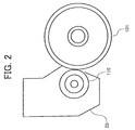
- the first cleaning apparatus 1 includes the brush roller 20.
- the brush roller 20 is brought into contact with the charging roller 110 which serves as a charging device.
- the brush roller 20 has a plurality of bristles of brushes (not shown) on its peripheral surface.
- the brush roller 20 and the charging roller 110 are supported rotationally against the main assembly of the process cartridge (FIG. 2).
- the brush roller 20 is supported by a bearing (not shown) which is integrated with the main assembly of the process cartridge.
- the bearing supports the brush roller 20 and the axis 20a which are attached slidable and rotational.
- the bearing has a slit (not shown) with the length parallel to the contact/separate direction.
- the bearing allows the brush roller 20 to be brought into contact by its weight with the charging roller 110.
- the brush roller 20 is made to rotate in synchronism with the rotation of the charging roller 110.
- a process cartridge 25 includes at least the first cleaning apparatus 1.
- the first cleaning apparatus 1 is an apparatus which forms the process cartridge 25 as well as the charging apparatus 110 and the photoreceptor 101.
- the first cleaning apparatus 1 cleans the charging roller 110.
- the photoreceptor 101 is driven for rotation in the direction of the arrow mark A by a drive resource (not shown) and the charging roller 110 is made to rotate by its weight driven by the rotation of the photoreceptor 101.
- the brush roller 20 is made to rotate by its weight driven by the charging roller 110.
- a pressing pressure from the brush roller 20 to the charging roller 110 is assigned by self-weight of the brush roller 20 in the embodiment, a member to restrict a pressing pressure to the charging roller 110 by the brush roller 20 is unneeded and the structure of a cleaning apparatus can be simplified, thereby reducing cost.
- the length of bristles of brush are approximately 2mm or less, bending moment can be reduced, which acts on the base edge of the bristles of brush which are elastically deformed and bent after pressed strongly against the peripheral surface of the charging roller 110. Therefore, bristles of brushes are prevented to be broken, an eternal deformation can be prevented and the brush roller 20 can be used longer.
- the thickness of the bristles of brushes is set as approximately 5 deniers or less and the density of bristles is approximately 15000 bristles/cm 2 or more.
- FIG. 3 an exemplary chart is shown for evaluation test performed with regard to cleaning capacity between the case where a conductive member is used as the brush roller 20 and the other case where a non-conductive member is used as a brush roller to clean toner particles adhesive to the charging roller 110.
- the evaluation test is performed in a fashion that after removing the brush roller 20 from the main body, the peripheral surface of the charging roller 110 is intentionally contaminated for testing with particles of toner.
- Each of brush rollers 20 with various kinds of members is sequentially applied.
- the density of the toner particles attached to brushing member can be calculated by varying the number of passage of sheets.
- Carbon-separated nylon is used as a member of the brush roller 20 which are applied to a conductive member and nylon is used as a member of the brush roller 20 which uses a non-conductive member.
- an image density (ID) indicates approximately 0.095 in the case of using the brush roller 20 with the conductive member and the slope of the chart shows a steep downward slope in terms of the ID when the brush roller 20 with a conductive member is used.
- FIG. 4 an exemplary table 1 to show two cases of cleaning will be illustrated.
- the brush roller 20 with a conductive member and the brush roller with a non-conductive member produce stable result in terms of removing particles of toner attached to the charging roller 110.
- the evaluation results of the aforementioned two cases, that is, when using the brush roller 20 with a conductive member and the brush roller with a non-conductive member are compared to each other. The evaluation is conducted in an identical manner to the evaluation of the FIG. 3.
- a member of the brush roller 20 with a conductive member and a member of the brush roller with a non-conductive member are respectively and substantially identical to the brush roller 20 and the brush roller in FIG. 3.
- FIG. 4 shows a result of the contamination of the charging roller 110 after passage of 45000.
- the ID is 0.79 in the center of the image of a sheet, for example.
- the result of FIG. 4 also shows that the conductive brush roller 20 can remove particles of toner on the charging roller 110 in more stable fashion and the brush roller 20 may be used for a time longer than the non-conductive brush roller.
- an image forming begins by a predetermined operation and the photoreceptor 101 is driven to rotate in the direction A.
- the photoreceptor 101 rotates, it undergoes various kinds of separate stages including the charging process performed by the charging roller 110, the exposure process by the laser beam 103, the developing process by the developing apparatus 104, the transfer process by the transfer apparatus 109 and the cleaning process by the second cleaning apparatus 106.
- the photoreceptor 101 repeats the next image forming step in which the photoreceptor 101 is charged again by the charging roller 110.
- toner particles cannot be removed by the second cleaning apparatus 106.
- the toner particles pass through the blade 106a.
- the particles of toner that have passed through the blade 106a are adhered to the charging roller 110.
- the particles of toner on the charging roller 110 are removed by the brush roller 20 driven for rotation by the charging roller 110.
- Paper dust is adhered to the photoreceptor 101 from the paper that is held in contact with the photoreceptor 101 in the transfer region 107 during the image transfer process. Likewise, the paper dust adhered to the photoreceptor 101 is not removed by the second cleaning apparatus 106 but is adhered to the charging roller 110 and accumulated thereon. In the same manner mentioned above, the paper dust that has adhered to the charging roller 110 in the above-described manner is removed by the brush roller 20. As above-described, foreign substance such as toner and paper dust, for example, is further removed because cleaning performance of the brush roller 20 is enhanced. Therefore, removing performance will be maintained for relatively a long time.
- toner is prepared by a polymerization way. Because charge counter mass ratio for each of the particles is uniform by every particle, transfer efficiency is enhanced in a transfer process performed statically.
- the amount of toner resides on the photoreceptor 101 is less than the amount of toner which is manufactured in other methods.
- the toner made in a polymerization way prevents dirt from adhering to the peripheral surface of the charging roller 110.
- the stranger the form of toner is the more efficient the removal efficiency by the second cleaning apparatus 106 is in comparison with when the form of the toner is like a pearl. Therefore, it is also effective to remove dirt that the toner is made such that the form of the toner is strange in terms of form, unable to keep the charging roller 110 clean with the passage of time.
- a cleaning apparatus and an image forming apparatus are explained.
- other members can also be used.
- a photoreceptor may be an object material to be cleaned.
- the photoreceptor includes the transfer apparatus such as the transfer apparatus 109 and transfer belt (not shown), the photoreceptor is termed as an object material to be cleaned.
- At least one of the charging rollers 110, the life span which is extended by the first cleaning apparatus 1 to a great extent, as well as the first cleaning apparatus 1 itself may be included in this embodiment.
- the process cartridge can be used longer as an assembly and unmatched convenience of operation is made the most of, though the first cleaning apparatus 1 does not necessarily include the process cartridge.
Landscapes
- Physics & Mathematics (AREA)
- General Physics & Mathematics (AREA)
- Cleaning In Electrography (AREA)
- Electrostatic Charge, Transfer And Separation In Electrography (AREA)
- Cleaning In General (AREA)
Applications Claiming Priority (2)
| Application Number | Priority Date | Filing Date | Title |
|---|---|---|---|
| JP2002303386A JP2004138816A (ja) | 2002-10-17 | 2002-10-17 | クリーニング装置及び画像形成装置 |
| JP2002303386 | 2002-10-17 |
Publications (2)
| Publication Number | Publication Date |
|---|---|
| EP1429210A2 true EP1429210A2 (de) | 2004-06-16 |
| EP1429210A3 EP1429210A3 (de) | 2004-06-23 |
Family
ID=32321586
Family Applications (1)
| Application Number | Title | Priority Date | Filing Date |
|---|---|---|---|
| EP03022595A Ceased EP1429210A3 (de) | 2002-10-17 | 2003-10-06 | Reinigungsvorrichtung mit einer elektroleitfähigen Reinigungsbürste |
Country Status (4)
| Country | Link |
|---|---|
| US (1) | US7139503B2 (de) |
| EP (1) | EP1429210A3 (de) |
| JP (1) | JP2004138816A (de) |
| CN (1) | CN1291287C (de) |
Families Citing this family (3)
| Publication number | Priority date | Publication date | Assignee | Title |
|---|---|---|---|---|
| JP5124546B2 (ja) * | 2009-08-31 | 2013-01-23 | 京セラドキュメントソリューションズ株式会社 | 画像形成装置のクリーニング装置及び画像形成装置 |
| JP5875404B2 (ja) * | 2012-02-21 | 2016-03-02 | キヤノン株式会社 | 印刷装置及びその制御方法、及びプログラム |
| JP5875406B2 (ja) | 2012-02-22 | 2016-03-02 | キヤノン株式会社 | 印刷装置及びその制御方法、及びプログラム |
Citations (7)
| Publication number | Priority date | Publication date | Assignee | Title |
|---|---|---|---|---|
| EP0327227A2 (de) | 1988-01-28 | 1989-08-09 | Xerox Corporation | Reinigungsbürste |
| JPH07140763A (ja) | 1993-11-19 | 1995-06-02 | Canon Inc | 画像形成装置 |
| JPH07210026A (ja) | 1994-01-13 | 1995-08-11 | Teijin Ltd | トナー定着装置のクリーニングロール用パイル布帛 |
| JPH0822173A (ja) | 1994-07-07 | 1996-01-23 | Ricoh Co Ltd | 画像形成装置 |
| EP0738938A1 (de) | 1995-04-21 | 1996-10-23 | Canon Kabushiki Kaisha | Bilderzeugungsgerät mit Zwischenübertragungselement |
| EP1229399A1 (de) * | 2001-01-25 | 2002-08-07 | Ricoh Company, Ltd. | Reinigungsvorrichtung und Bilderzeugungsgerät |
| US6442367B1 (en) | 1999-05-31 | 2002-08-27 | Konica Corporation | Electrophotographic image forming method, electrophotographic image forming apparatus, and processing cartridge |
Family Cites Families (19)
| Publication number | Priority date | Publication date | Assignee | Title |
|---|---|---|---|---|
| US4361922A (en) * | 1981-01-06 | 1982-12-07 | Schlegel Corporation | Cleaning brush for electrostatic copiers, printers and the like |
| JPH01219881A (ja) * | 1988-02-29 | 1989-09-01 | Alps Electric Co Ltd | クリーニング方法及び装置 |
| JPH0695570A (ja) | 1990-12-10 | 1994-04-08 | Ricoh Co Ltd | 電子写真装置のファ−ブラシクリ−ニング装置 |
| US5233394A (en) * | 1991-05-29 | 1993-08-03 | Mita Industrial Co., Ltd. | Transfer device for use in an image forming apparatus |
| US5371578A (en) * | 1991-06-21 | 1994-12-06 | Minolta Camera Kabushiki Kaisha | Image forming apparatus including means for removing counter charged toner from the charging means |
| US5722015A (en) * | 1996-04-30 | 1998-02-24 | Eastman Kodak Company | Method and apparatus for adjusting the charge on toner |
| US6070043A (en) * | 1997-01-17 | 2000-05-30 | Mita Industrial | Device for cleaning a transfer belt of an image-forming machine |
| JP3654560B2 (ja) * | 1997-08-18 | 2005-06-02 | 株式会社リコー | 画像形成装置 |
| JPH11167251A (ja) * | 1997-10-03 | 1999-06-22 | Ricoh Co Ltd | 画像形成装置及び画像形成方法 |
| JPH11282223A (ja) * | 1998-02-02 | 1999-10-15 | Ricoh Co Ltd | 画像形成装置、および光学検知システム |
| JP3565709B2 (ja) * | 1998-04-10 | 2004-09-15 | 株式会社リコー | 電子写真式画像形成装置 |
| JP2000122448A (ja) * | 1998-10-13 | 2000-04-28 | Ricoh Co Ltd | 画像形成装置 |
| CN1172222C (zh) * | 1998-10-14 | 2004-10-20 | 株式会社理光 | 墨粉浓度控制方法及使用该方法的图像形成装置 |
| US6175711B1 (en) * | 1998-10-16 | 2001-01-16 | Fuji Xerox Co., Ltd. | Image forming apparatus having a toner diffuser |
| KR100348374B1 (ko) * | 1999-01-14 | 2002-08-10 | 가부시키가이샤 리코 | 화상 형성 장치 |
| JP2000275983A (ja) * | 1999-03-24 | 2000-10-06 | Toshiba Tec Corp | 転写装置、及びこの転写装置を備えた画像形成装置 |
| US6430379B1 (en) * | 1999-10-21 | 2002-08-06 | Fuji Xerox Co., Ltd. | Image forming apparatus using intermediate transfer medium |
| US6757505B2 (en) * | 2001-01-25 | 2004-06-29 | Ricoh Company, Ltd. | Image forming apparatus and cleaning device therefor |
| JP4058591B2 (ja) * | 2001-08-17 | 2008-03-12 | 富士ゼロックス株式会社 | 画像形成装置 |
-
2002
- 2002-10-17 JP JP2002303386A patent/JP2004138816A/ja active Pending
-
2003
- 2003-10-06 EP EP03022595A patent/EP1429210A3/de not_active Ceased
- 2003-10-14 CN CN200310101099.6A patent/CN1291287C/zh not_active Expired - Fee Related
- 2003-10-17 US US10/686,646 patent/US7139503B2/en not_active Expired - Lifetime
Patent Citations (7)
| Publication number | Priority date | Publication date | Assignee | Title |
|---|---|---|---|---|
| EP0327227A2 (de) | 1988-01-28 | 1989-08-09 | Xerox Corporation | Reinigungsbürste |
| JPH07140763A (ja) | 1993-11-19 | 1995-06-02 | Canon Inc | 画像形成装置 |
| JPH07210026A (ja) | 1994-01-13 | 1995-08-11 | Teijin Ltd | トナー定着装置のクリーニングロール用パイル布帛 |
| JPH0822173A (ja) | 1994-07-07 | 1996-01-23 | Ricoh Co Ltd | 画像形成装置 |
| EP0738938A1 (de) | 1995-04-21 | 1996-10-23 | Canon Kabushiki Kaisha | Bilderzeugungsgerät mit Zwischenübertragungselement |
| US6442367B1 (en) | 1999-05-31 | 2002-08-27 | Konica Corporation | Electrophotographic image forming method, electrophotographic image forming apparatus, and processing cartridge |
| EP1229399A1 (de) * | 2001-01-25 | 2002-08-07 | Ricoh Company, Ltd. | Reinigungsvorrichtung und Bilderzeugungsgerät |
Also Published As
| Publication number | Publication date |
|---|---|
| JP2004138816A (ja) | 2004-05-13 |
| EP1429210A3 (de) | 2004-06-23 |
| CN1291287C (zh) | 2006-12-20 |
| CN1497397A (zh) | 2004-05-19 |
| US20040131405A1 (en) | 2004-07-08 |
| US7139503B2 (en) | 2006-11-21 |
Similar Documents
| Publication | Publication Date | Title |
|---|---|---|
| US6987944B2 (en) | Cleaning device and image forming apparatus using the cleaning device | |
| US6035158A (en) | Image forming apparatus and belt unit thereof | |
| US6799012B2 (en) | Cleaning device and image forming apparatus using the same | |
| US7822356B2 (en) | Image forming apparatus | |
| JP3762241B2 (ja) | 画像形成装置およびクリーニング装置 | |
| EP0778503B1 (de) | Elektrophotographische Bilderzeugungsvorrichtung mit positiv geladenem Toner | |
| US7684732B2 (en) | Process unit and image forming apparatus including the same | |
| EP1494088B1 (de) | Reinigungswalze mit besonderen Borsten, in Bilderzeugungsgerät und Arbeitseinheit zum Reinigen einer Kontaktaufladevorrichtung, entsprechende Verfahren zum Entfernen von Ablagerungen | |
| US7447455B2 (en) | Color image forming apparatus and mono color printing method thereof | |
| JP2002149031A (ja) | 画像形成装置 | |
| US7139503B2 (en) | Cleaning apparatus with conductive member | |
| JP4671316B2 (ja) | クリーニング装置 | |
| JP2004126506A (ja) | 画像形成装置 | |
| JP3574624B2 (ja) | クリーニング装置、およびそれを備える画像形成装置 | |
| US6144834A (en) | Self biasing, extended nip electrostatic cleaner | |
| CN1175711A (zh) | 减少采用静电复印显影系统的图象形成设备反转印的装置和方法 | |
| WO2001022173A1 (en) | Electrophotographic image forming device, intermediate transfer body and electrophotograpic image forming method | |
| JP3756090B2 (ja) | 画像形成装置 | |
| US20250138468A1 (en) | Electrostatic collecting device, image forming device, and cleaning device | |
| JP2003208068A (ja) | 像担持体クリーニング装置及び該装置を備えた画像形成装置 | |
| JP3758653B2 (ja) | 感光体研磨装置及びこれを備えた画像形成装置 | |
| JP2007101683A (ja) | クリーニング装置及びこれを用いた画像形成装置 | |
| JP2003186364A (ja) | 画像形成装置 | |
| JP2004219872A (ja) | 画像形成装置 | |
| JP2003015491A (ja) | 画像形成装置 |
Legal Events
| Date | Code | Title | Description |
|---|---|---|---|
| PUAI | Public reference made under article 153(3) epc to a published international application that has entered the european phase |
Free format text: ORIGINAL CODE: 0009012 |
|
| PUAL | Search report despatched |
Free format text: ORIGINAL CODE: 0009013 |
|
| AK | Designated contracting states |
Kind code of ref document: A2 Designated state(s): AT BE BG CH CY CZ DE DK EE ES FI FR GB GR HU IE IT LI LU MC NL PT RO SE SI SK TR |
|
| AX | Request for extension of the european patent |
Extension state: AL LT LV MK |
|
| AK | Designated contracting states |
Kind code of ref document: A3 Designated state(s): AT BE BG CH CY CZ DE DK EE ES FI FR GB GR HU IE IT LI LU MC NL PT RO SE SI SK TR |
|
| AX | Request for extension of the european patent |
Extension state: AL LT LV MK |
|
| 17P | Request for examination filed |
Effective date: 20040720 |
|
| AKX | Designation fees paid |
Designated state(s): DE ES FR GB IT NL |
|
| RBV | Designated contracting states (corrected) |
Designated state(s): DE ES FR GB IT NL |
|
| 17Q | First examination report despatched |
Effective date: 20110413 |
|
| STAA | Information on the status of an ep patent application or granted ep patent |
Free format text: STATUS: THE APPLICATION HAS BEEN REFUSED |
|
| 18R | Application refused |
Effective date: 20140430 |