EP1429138A1 - NONDESTRUCTIVE ANALYSIS METHOD AND NONDESTRUCTIVE ANALYSIS DEVICE AND SPECIFIC OBJECT BY THE METHOD/DEVICE - Google Patents
NONDESTRUCTIVE ANALYSIS METHOD AND NONDESTRUCTIVE ANALYSIS DEVICE AND SPECIFIC OBJECT BY THE METHOD/DEVICE Download PDFInfo
- Publication number
- EP1429138A1 EP1429138A1 EP02743766A EP02743766A EP1429138A1 EP 1429138 A1 EP1429138 A1 EP 1429138A1 EP 02743766 A EP02743766 A EP 02743766A EP 02743766 A EP02743766 A EP 02743766A EP 1429138 A1 EP1429138 A1 EP 1429138A1
- Authority
- EP
- European Patent Office
- Prior art keywords
- rays
- transmission
- analyzer crystal
- type analyzer
- diffraction
- Prior art date
- Legal status (The legal status is an assumption and is not a legal conclusion. Google has not performed a legal analysis and makes no representation as to the accuracy of the status listed.)
- Withdrawn
Links
- 238000004458 analytical method Methods 0.000 title claims abstract description 83
- 238000000034 method Methods 0.000 title description 9
- 239000013078 crystal Substances 0.000 claims abstract description 251
- 230000005540 biological transmission Effects 0.000 claims abstract description 58
- 230000009471 action Effects 0.000 claims abstract description 41
- 230000001678 irradiating effect Effects 0.000 claims description 22
- 238000012545 processing Methods 0.000 claims description 13
- 238000003325 tomography Methods 0.000 claims description 6
- 238000010586 diagram Methods 0.000 description 13
- XUIMIQQOPSSXEZ-UHFFFAOYSA-N Silicon Chemical compound [Si] XUIMIQQOPSSXEZ-UHFFFAOYSA-N 0.000 description 6
- 229910052710 silicon Inorganic materials 0.000 description 6
- 239000010703 silicon Substances 0.000 description 6
- 230000000694 effects Effects 0.000 description 5
- 239000002131 composite material Substances 0.000 description 4
- 239000003814 drug Substances 0.000 description 3
- 229940079593 drug Drugs 0.000 description 3
- 238000005516 engineering process Methods 0.000 description 3
- 241000251468 Actinopterygii Species 0.000 description 2
- ZOXJGFHDIHLPTG-UHFFFAOYSA-N Boron Chemical compound [B] ZOXJGFHDIHLPTG-UHFFFAOYSA-N 0.000 description 2
- 241000238631 Hexapoda Species 0.000 description 2
- 206010028980 Neoplasm Diseases 0.000 description 2
- 229910052796 boron Inorganic materials 0.000 description 2
- 201000011510 cancer Diseases 0.000 description 2
- 238000011161 development Methods 0.000 description 2
- 239000000835 fiber Substances 0.000 description 2
- 235000013305 food Nutrition 0.000 description 2
- 238000003384 imaging method Methods 0.000 description 2
- 239000002547 new drug Substances 0.000 description 2
- 229920001778 nylon Polymers 0.000 description 2
- 230000008569 process Effects 0.000 description 2
- 230000009467 reduction Effects 0.000 description 2
- 238000012916 structural analysis Methods 0.000 description 2
- 241001465754 Metazoa Species 0.000 description 1
- 238000002441 X-ray diffraction Methods 0.000 description 1
- 238000000333 X-ray scattering Methods 0.000 description 1
- XAGFODPZIPBFFR-UHFFFAOYSA-N aluminium Chemical compound [Al] XAGFODPZIPBFFR-UHFFFAOYSA-N 0.000 description 1
- 229910052782 aluminium Inorganic materials 0.000 description 1
- 230000008033 biological extinction Effects 0.000 description 1
- 230000015572 biosynthetic process Effects 0.000 description 1
- 210000004556 brain Anatomy 0.000 description 1
- 238000002591 computed tomography Methods 0.000 description 1
- 238000009833 condensation Methods 0.000 description 1
- 230000005494 condensation Effects 0.000 description 1
- 238000013461 design Methods 0.000 description 1
- 238000010894 electron beam technology Methods 0.000 description 1
- 230000008030 elimination Effects 0.000 description 1
- 238000003379 elimination reaction Methods 0.000 description 1
- 230000002349 favourable effect Effects 0.000 description 1
- 238000002594 fluoroscopy Methods 0.000 description 1
- 239000012770 industrial material Substances 0.000 description 1
- 238000007689 inspection Methods 0.000 description 1
- 239000007788 liquid Substances 0.000 description 1
- 210000004185 liver Anatomy 0.000 description 1
- 238000012986 modification Methods 0.000 description 1
- 230000004048 modification Effects 0.000 description 1
- 229920000642 polymer Polymers 0.000 description 1
- 102000004169 proteins and genes Human genes 0.000 description 1
- 108090000623 proteins and genes Proteins 0.000 description 1
- 239000004065 semiconductor Substances 0.000 description 1
- 230000035945 sensitivity Effects 0.000 description 1
- 239000007787 solid Substances 0.000 description 1
- 239000000126 substance Substances 0.000 description 1
- 230000002195 synergetic effect Effects 0.000 description 1
- 238000003786 synthesis reaction Methods 0.000 description 1
- 238000004876 x-ray fluorescence Methods 0.000 description 1
Images


Classifications
-
- G—PHYSICS
- G01—MEASURING; TESTING
- G01N—INVESTIGATING OR ANALYSING MATERIALS BY DETERMINING THEIR CHEMICAL OR PHYSICAL PROPERTIES
- G01N23/00—Investigating or analysing materials by the use of wave or particle radiation, e.g. X-rays or neutrons, not covered by groups G01N3/00 – G01N17/00, G01N21/00 or G01N22/00
- G01N23/20—Investigating or analysing materials by the use of wave or particle radiation, e.g. X-rays or neutrons, not covered by groups G01N3/00 – G01N17/00, G01N21/00 or G01N22/00 by using diffraction of the radiation by the materials, e.g. for investigating crystal structure; by using scattering of the radiation by the materials, e.g. for investigating non-crystalline materials; by using reflection of the radiation by the materials
- G01N23/207—Diffractometry using detectors, e.g. using a probe in a central position and one or more displaceable detectors in circumferential positions
-
- G—PHYSICS
- G01—MEASURING; TESTING
- G01N—INVESTIGATING OR ANALYSING MATERIALS BY DETERMINING THEIR CHEMICAL OR PHYSICAL PROPERTIES
- G01N23/00—Investigating or analysing materials by the use of wave or particle radiation, e.g. X-rays or neutrons, not covered by groups G01N3/00 – G01N17/00, G01N21/00 or G01N22/00
- G01N23/02—Investigating or analysing materials by the use of wave or particle radiation, e.g. X-rays or neutrons, not covered by groups G01N3/00 – G01N17/00, G01N21/00 or G01N22/00 by transmitting the radiation through the material
- G01N23/04—Investigating or analysing materials by the use of wave or particle radiation, e.g. X-rays or neutrons, not covered by groups G01N3/00 – G01N17/00, G01N21/00 or G01N22/00 by transmitting the radiation through the material and forming images of the material
Definitions
- the invention of this application relates to a nondestructive analysis method, a nondestructive analysis device, and a specific object by the method/device.
- the object is irradiated with monochromatic X-rays, refraction X-rays from the object are introduced to an analyzer crystal (also referred to as crystal analysis plate, crystal analysis device, etc.).
- an analyzer crystal also referred to as crystal analysis plate, crystal analysis device, etc.
- This utilizes the fact that the analyzer crystal has an angular-analysis capability.
- the image obtained by the angular-analysis is paired with a similar image having different contrast between the transmission beam and diffraction beam (an image of opposite signs; specifically, a white-and-black image if the other image is black-and-white).
- the nondestructive analysis technique of Japanese Patent No. 2694049 has the problem that when the angular-analysis capability of the transmission-type analyzer crystal is utilized, the effect of the wavelength distribution remains, since no consideration is given to parallelization between the atomic lattice planes of the monochromator for generating the monochromatic X-rays and the atomic lattice planes of the analyzer crystal. Furthermore, there is the problem of requiring complicated operations for storing a white-and-black image and a black-and-white image with successive rotations of the analyzer crystal and forming a high contrast image through a computer since no consideration is given to forming the transmission-type analyzer crystal of a certain thickness and it is thus impossible to obtain the desired image of the object at a time.
- any of the foregoing nondestructive analysis techniques can only obtain poor-contrast, hard-to-recognize images due to the configuration that is chiefly intended to obtain an X-ray bright-field image, or an X-ray image or information on an object, superimposed with X-rays affected by the intensity of the X-rays incident directly in the X-ray bright-field image. It has thus been impossible to obtain nothing other than poor-contrast, hard-to-recognize images.
- an object of the invention is to solve the problems of the conventional art and provide a new nondestructive analysis method and nondestructive analysis device, as well as a specific object by those nondestructive analysis method and device, which can realize a configuration chiefly intended to obtain an X-ray dark-field image in particular, or an X-ray image or object information by X-rays, unaffected by the intensities of the X-rays incident directly with an elimination or a reduction of an unnecessary illuminated background of X-rays, and can obtain a high-contrast image from inside an object at a time with facility.
- the invention of this application firstly provides a nondestructive analysis method for irradiating an object with monochromatic parallel X-rays, making transmission X-rays, refraction X-rays, diffraction X-rays, or small angle scattering X-rays from the object incident on a transmission-type analyzer crystal, and obtaining an image inside the object by X-rays emitted from the transmission-type analyzer crystal, characterized in that: the thickness of the transmission-type analyzer crystal is initially set to such a thickness that when there is no object, either ones of X-rays along a forward diffraction direction and X-rays along a diffraction direction obtained by a dynamical diffraction action of the transmission-type analyzer crystal have an intensity of nearly zero as compared to the intensity of the others in terms of the intensity of X-rays less affected by X-rays incident directly; and either ones or both of the X-rays along the forward dif
- the present invention in secondly provides a nondestructive analysis method for irradiating an object with monochromatic parallel X-rays, making transmission X-rays, refraction X-rays, diffraction X-rays, or small angle scattering X-rays from the object incident on a transmission-type analyzer crystal, and obtaining an image inside the object by X-rays emitted from the transmission-type analyzer crystal, characterized in that: the thickness of the transmission-type analyzer crystal is initially set to such a thickness that when there is no object, either ones of X-rays along a forward diffraction direction and X-rays along a diffraction direction obtained by a dynamical diffraction action of the transmission-type analyzer crystal have an intensity of nearly zero as compared to the intensity of the others in terms of the intensity of X-rays less affected by X-rays incident directly; and either one or both of an X-ray dark-field image and an X-ray bright-field image are
- the invention of this application thirdly provides a nondestructive analysis method for irradiating an object with monochromatic parallel X-rays, making transmission X-rays, refraction X-rays, diffraction X-rays, or small angle scattering X-rays from the object incident on a reflection-type analyzer crystal, and obtaining an image inside the object by X-rays emitted from the reflection-type analyzer crystal, characterized in that; transmitted transmission X-rays are provided by a dynamical diffraction action of the reflection-type analyzer crystal.
- the present invention in 4th provides a nondestructive analysis method for irradiating an object with monochromatic parallel X-rays, making transmission X-rays, refraction X-rays, diffraction X-rays, or small angle scattering X-rays from the object incident on a reflection-type analyzer crystal, and obtaining an image inside the object by X-rays emitted from the reflection-type analyzer crystal, characterized in that: a transmitted X-ray dark-field image is provided by a dynamical diffraction action of the reflection-type analyzer crystal.
- the invention of this application in 5th provides a nondestructive analysis device for irradiating an object with monochromatic parallel X-rays, making transmission X-rays, refraction X-rays, diffraction X-rays, or small angle scattering X-rays from the object incident on a transmission-type analyzer crystal, and obtaining an image inside the object by X-rays emitted from the transmission-type analyzer crystal, characterized in that: the thickness of the transmission-type analyzer crystal is initially set to such a thickness that when there is no object, either ones of X-rays along a forward diffraction direction and X-rays along a diffraction direction obtained by a dynamical diffraction action of the transmission-type analyzer crystal have an intensity of nearly zero as compared to the intensity of the others in terms of the intensity of X-rays less affected by X-rays incident directly; and either ones or both of the X-rays along the forward diffraction direction and the
- the present invention in 6th provides a nondestructive analysis device for irradiating an object with monochromatic parallel X-rays, making transmission X-rays, refraction X-rays, diffraction X-rays, or small angle scattering X-rays from the object incident on a transmission-type analyzer crystal, and obtaining an image inside the object by X-rays emitted from the transmission-type analyzer crystal, characterized in that: the thickness of the transmission-type analyzer crystal is initially set to such a thickness that when there is no object, either ones of X-rays along a forward diffraction direction and X-rays along a diffraction direction obtained by a dynamical diffraction action of the transmission-type analyzer crystal have an intensity of nearly zero as compared to the intensity of the others in terms of the intensity of X-rays less affected by X-rays incident directly; and either one or both of an X-ray dark-field image and an X-ray bright-field image are
- the invention of this application in 7th provides a nondestructive analysis device for irradiating an object with monochromatic parallel X-rays, making transmission X-rays, refraction X-rays, diffraction X-rays, or small angle scattering X-rays from the object incident on a transmission-type analyzer crystal, and obtaining an image inside the object by X-rays emitted from the transmission-type analyzer crystal, characterized in that: the transmission-type analyzer crystal is initially shaped so that it periodically exhibit such thicknesses that when there is no object, either ones of X-rays along a forward diffraction direction and X-rays along a diffraction direction obtained by a dynamical diffraction action of the transmission-type analyzer crystal have an intensity of nearly zero as compared to the intensity of the others in terms of the intensity of X-rays less affected by X-rays incident directly; a slit plate is arranged on an output side of the transmission-type analyzer
- the invention of this application in 8th provides a nondestructive analysis device for irradiating an object with monochromatic parallel X-rays, making transmission X-rays, refraction X-rays, diffraction X-rays, or small angle scattering X-rays from the object incident on a reflection-type analyzer crystal, and obtaining an image inside the object by X-rays emitted from the reflection-type analyzer crystal, characterized in that; transmitted transmission X-rays are obtained by a dynamical diffraction action of the reflection-type analyzer crystal.
- the present invention in 9th provides a nondestructive analysis device for irradiating an object with monochromatic parallel X-rays, making transmission X-rays, refraction X-rays, diffraction X-rays, or small angle scattering X-rays from the object incident on a reflection-type analyzer crystal, and obtaining an image inside the object by X-rays emitted from the reflection-type analyzer crystal, characterized in that: a transmitted X-ray dark-field image is provided by a dynamical diffraction action of the reflection-type analyzer crystal.
- the invention of this application in 10th provides a nondestructive analysis device for irradiating an object with monochromatic parallel X-rays, making transmission X-rays, refraction X-rays, diffraction X-rays, or small angle scattering X-rays from the object incident on an analyzer crystal, and obtaining an image inside the object by X-rays emitted from the analyzer crystal, characterized in that: the analyzer crystal is usable as both transmission-type and reflection-type analyzer crystals, being configured to satisfy both a thickness condition that either ones of X-rays along a forward diffraction direction and X-rays along a diffraction direction obtained by a dynamical diffraction action of the analyzer crystal have an intensity of nearly zero as compared to the intensity of the others in terms of the intensity of X-rays less affected by X-rays incident directly, and a thickness condition that transmission X-rays, refraction X-rays, diffraction
- the present invention in 11th provides a nondestructive analysis device for irradiating an object with monochromatic parallel X-rays, making transmission X-rays, refraction X-rays, diffraction X-rays, or small angle scattering X-rays from the object incident on an analyzer crystal, and obtaining an image inside the object by X-rays emitted from the analyzer crystal, characterized in that: the analyzer crystal is usable as both transmission-type and reflection-type analyzer crystals, being configured to satisfy both a thickness condition that either ones of X-rays along a forward diffraction direction and X-rays along a diffraction direction obtained by a dynamical diffraction action of the analyzer crystal have an intensity of nearly zero as compared to the intensity of the others in terms of the intensity of X-rays less affected by X-rays incident directly, and a thickness condition that transmission X-rays, refraction X-rays, diffraction X-ray
- the invention of this application in 12th provides the nondestructive analysis device according to the already described invention, characterized in that the reflection-type analyzer crystal is an asymmetric analyzer crystal.
- the present invention in 13th provides the nondestructive analysis device according to the already described invention, characterized by comprising: a X-ray detecting device for detecting either one or both of the X-ray dark-field image and the X-ray bright-field image; and image processing equipment for creating an image by using detecting data from the X-ray detecting device.
- the present invention in 14th provides the nondestructive analysis device according to the already described invention, characterized in that the X-ray detecting device is a two-dimensional detector or a line sensor one-dimensional detector.
- the present invention in 15th provides the nondestructive analysis device according to the already described invention, characterized in that the image processing equipment is capable of creating either one or both of X-ray dark-field tomography and X-ray bright-field tomography, or either one or both of X-ray dark-field stereography and X-ray bright-field stereography.
- the present invention in 16th provides the nondestructive analysis device according to the already described invention, characterized by comprising means for monochromating and parallelizing X-rays from an X-ray source.
- the present invention in 17th provides the nondestructive analysis device according to the already described invention, characterized in that the means for monochromating and parallelizing the X-rays is a symmetric or asymmetric monochromator.
- the present invention in 18th provides the nondestructive analysis device according to the already described invention, characterized in that atomic lattice planes of the symmetric or asymmetric monochromator and atomic lattice planes of the transmission-type analyzer crystal or reflection-type analyzer crystal are parallel with each other.
- the present invention in 19th provides the nondestructive analysis device according to the already described invention, characterized in that transmission X-rays, refraction X-rays, diffraction X-rays, or small angle scattering X-rays from the object are made incident on the transmission-type analyzer crystal or reflection-type analyzer crystal through one or a plurality of asymmetric monochromators.
- the present invention in 20th provides the nondestructive analysis device according to the already described invention, characterized in that either one or both of the X-ray dark-field image and the X-ray bright-field image obtained from the transmission-type analyzer crystal are output through one or a plurality of asymmetric monochromators.
- the invention of this application in 21st provides the nondestructive analysis method according to the already described invention, characterized in that an electromagnetic wave other than the X-rays or a corpuscular beam is used instead of the X-rays.
- the present invention in 22nd provides the nondestructive analysis device according to the already described invention, characterized in that an electromagnetic wave other than the X-rays or a corpuscular beam is used instead of the X-rays.
- the present invention in 23rd provides a specific object identified by analyzing an internal structure of an object by using the nondestructive analysis method according to the already described invention, or the nondestructive analysis device according to the already described invention.
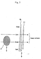
- An object (2) to be analyzed is irradiated with monochromatic parallel X-rays I i (1).
- Transmission X-rays from the object (2), and such X-rays as refraction X-rays, diffraction X-rays, and even small angle scattering X-rays (for convenience of explanation, these will be collectively referred to as refraction X-rays, and the like) (3) are made incident on a transmission-type analyzer crystal (4a) to utilize the dynamical diffraction action of the transmission-type analyzer crystal (4a) at this time.
- the thickness of the transmission-type analyzer crystal (4a) is initially set to such a thickness that when there is no object, either ones of the X-rays (41a) along the forward diffraction direction (also referred to, equivalently, as diffraction X-rays along the incident direction or X-rays along the transmission diffraction direction) and the X-rays (42a) along the diffraction direction obtained by the dynamical diffraction action of the transmission-type analyzer crystal (4a) show an intensity of approximately zero (including exactly zero; the same holds hereinafter) as compared to the intensity of the others in terms of the intensity of X-rays less affected by the X-rays incident directly.
- the dynamical diffraction action means an effect resulting from multiple scattering of X-rays in a nearly perfect crystal.
- the X-rays are thus output as divided into a wave (called 0-wave) along the forward direction (also referred to as incident direction or transmission direction) and a wave (called G-wave) along the diffraction direction, the O-wave and the G-wave being reflected for a plurality of times repeatedly on a number of crystal lattice planes in the crystal.
- the thickness H of the transmission-type analyzer crystal (4a) should be selected so that either the intensity of I O for O-wave or the intensity of I G for G-wave will be approximately zero, in other words so that either one, compared to the other, that may receive less influence of the X-rays incident directly.
- the wave that gives approximately the zero intensity forms the dark-field image (5) and the other wave forms the bright-field image (6). That is, the following relationship holds:
- Fig. 5 illustrates the theoretical curves of the dynamical diffraction actions I O (W) and I G (W) in more details.
- the O-wave constructs an X-ray dark-field image (5) under the dynamical diffraction action I O (W)
- the G-wave constructs an X-ray bright-field image (6) under the dynamical diffraction action I G (W).
- the G-wave constructs an X-ray dark-field image (5) under the dynamical diffraction action I G (W)
- the O-wave constructs an X-ray bright-field image (6) under the dynamical diffraction action I O (W).
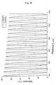
- the transmission-type analyzer crystal (4a) is made of a diamond-type silicon analyzer crystal having a size of crystal lattice of 5.4311 angstroms and silicon 4,4,0 reflection is used, the thicknesses H at which I o or I G falls to nearly zero with respect to X-rays of 35 keV in energy appear in periods of 67.5 ⁇ m as illustrated in Fig. 6.
- the transmission-type analyzer crystal (4a) may be formed in a wedge shape or the like that exhibits the foregoing thicknesses periodically, in which case X-ray dark-field images (5) and X-ray bright-field images (6) are obtained in a slit fashion successively as shown in Fig. 6. Consequently, as illustrated in Fig.
- a slit plate (11) is arranged on the output side of the transmission-type analyzer crystal (4a) so that this slit plate (11) and the wedge shape transmission-type analyzer crystal (4a) can be slid and moved relative to the object (2), or conversely the object (2) can be slid and moved relative to the slit plate (11) and the wedge shape transmission-type analyzer crystal (4a), to obtain a plurality of slit-like images through the slit plate (11).
- Those images can be synthesized into an image or images of any fields of view, or equivalently, either one or both of an X-ray dark-field image and an X-ray bright-field image.
- the transmission-type analyzer crystal (4a) capable of such intensity settings may have thicknesses in the range of, e.g., several micrometers to several tens of millimeters while the range varies, as can be seen from the foregoing equations 1, with various factors including the size of the crystal lattice, and the intensities and wavelengths of the X-rays, refraction X-rays, and the like (3). Moreover, in practical terms, it is desirable that the transmission-type analyzer crystal (4a) in this case have a required finishing precision of 1% or less the thickness.
- the X-rays (41a) along the forward diffraction direction and the X-rays (42a) along the diffraction direction from the transmission-type analyzer crystal (4a) given the foregoing thickness setting are detected by the X-ray detecting devices (10) (see Figs. 1 and 2), and images are created by image processing equipment (not shown, but is configured capable of receiving the detecting data of X-rays) by using the detecting data of X-rays from the X-ray detecting devices (10).
- the X-ray dark-field image (5) is created from I O
- the X-ray bright-field image (6) is created from I G .
- a reflection-type analyzer crystal (4b) when a reflection-type analyzer crystal (4b) is used, an object (2) to be analyzed is irradiated with monochromatic parallel X-rays I i (1) via an asymmetric monochromator (8). Refraction X-rays and the like (3) from the object (2) are made incident on the reflection-type analyzer crystal (4b), at which time the dynamical diffraction action of the reflection-type analyzer crystal (4b) is utilized so that in the reflection-type analyzer crystal (4b), the refraction X-rays and the like (3) from the object (2) satisfy the diffraction condition and are transmitted by the dynamical diffraction action of the reflection-type analyzer crystal (4b).
- the angle between the monochromatic parallel X-rays (1) and the reflection-type analyzer crystal (4b) and the thickness of the reflection-type analyzer crystal (4b) are also given settings at which it possible to obtain the X-ray dark-field image (5) that is created from the transmission X-rays I T (41b) from the reflection-type analyzer crystal (4b).
- the angle between the monochromatic parallel X-rays (1) and the reflection-type analyzer crystal (4b) may also be given another setting to satisfy the diffraction condition by the dynamical diffraction action of the reflection-type analyzer crystal (4b), so as to obtain an X-ray bright-field image (6) that is created by reflection X-rays I B (42b) according to the Bragg reflection condition.
- the X-rays from the transmission-type analyzer crystal (4a) or the reflection-type analyzer crystal (4b) are detected by the X-ray detecting devices (10).
- These X-ray detecting devices (10) may be flat-type panels, columnar panels, or the like based on two-dimensional detectors (such as an X-ray film, a nuclear plate, an X-ray image pick-up tube, an X-ray fluorescence multiplier tube, an X-ray image intensifier, an X-ray imaging plate, an X-ray CCD, and an X-ray imaging detector by amorphous element), or line sensor one-dimensional detectors.
- Which X-ray detecting devices (10) to use may be selected arbitrarily depending on the type, condition, and the like of the object (2) to be analyzed.
- combination scanning of, for example, object movement, rotation, tilt, etc., with the line sensor one-dimensional detectors or two-dimensional detectors is useful for the creation of tomography and stereography by image processing equipment to be described later.
- X-ray computed tomography technology can be introduced to obtain new nondestructive analysis images.
- the image processing equipment (not shown) is capable of creating ordinary X-ray scattering images as either one or both of the X-ray dark-field image (5) and the X-ray bright-field image (6), based on the detecting data of X-rays from the X-ray detecting devices (10) described above.
- the image processing equipment may have the capability of creating X-ray dark-field and bright-field tomography and stereography through image synthesis processing or the like.
- An X-ray source (not shown) of the X-rays for the object (2) to be irradiated with may also be selected arbitrarily according to the object (2) to be analyzed.
- the X-rays from the X-ray source described above must reach the object (2) in the form of a monochromatic beam as well as a parallel beam (also referred to as plane wave).
- This monochromatization and parallelization can be effected, for example, by using a parabolic mirror made of a multiple layer mirror.
- a parallel beam may be created through condensation by a parabolic reflection mirror or capillary, followed by monochromatization by monochromators or asymmetric monochromators.
- the incident X-rays (7) from the X-ray source (not shown) are monochromated and parallelized by the asymmetric monochromator (8).
- the direction of the monochromatic parallel X-rays (1) from the asymmetric monochromator (8)(not shown) is changed by the collimator (9) for irradiation of the object (2).
- This collimator (9) itself may also be used as a monochromator for monochromatization and parallelization.
- the means for monochromatization and parallelization are not limited thereto. Various means publicly known heretofore may be used as appropriate.
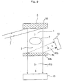
- the monochromator or the asymmetric monochromator (8) is used as the monochromatization and parallelization means, it is of extreme importance that the monochromator or the asymmetric monochromator (8) is arranged with its atomic lattice planes (80) in parallel with the atomic lattice planes (40a), (40b) of the transmission-type analyzer crystal (4a) or the reflection-type analyzer crystal (4b) as shown in Figs. 1,.2, 8, and 9 (in Fig. 2, the atomic lattice planes (90) of the collimator (9) are also arranged in parallel).
- Fig. 1 shows the asymmetric monochromator (8) and the transmission-type analyzer (4a) which are integrated with each other
- Fig. 2 shows the collimator (9) and the transmission-type analyzer crystal (4a) which are unified with each other into a channel-cut shape
- Fig. 8 shows the asymmetric monochromator (8) and the reflection-type analyzer crystal (4b) which are unified with each other into a channel-cut shape. It will be appreciated that the two may be separated or coupled loosely.
- Fig. 9 shows an example where the asymmetric monochromator (8) and the reflection-type analyzer crystal (4b) are arranged separately.
- the asymmetric monochromator (8), the collimator (9), and the transmission-type analyzer crystal (4a) or the reflection-type analyzer crystal (4b) must be assembled and adjusted so that their atomic lattice planes (80), (90), (40a), (40b) are in parallel with each other.
- the incident X-rays (7) from the X-ray source (not shown) are monochromated and parallelized by the asymmetric monochromator (8), the object (2) is irradiated with the monochromatic parallel X-rays (1), and the refraction X-rays and the like (3) from the object (2) are further passed through one or a plurality of composite asymmetric monochromators (8a), (8b) before incidence on the transmission-type analyzer crystal (4a), as illustrated in Fig. 10, for example.
- the X-rays (41a) along the forward diffraction direction and the X-rays (42a) along the diffraction direction from the transmission-type analyzer crystal (4a) may be further passed through one or a plurality of composite asymmetric monochromators (8c), (8d) before output to the X-ray detecting devices (10).
- This also makes it possible to obtain the X-ray dark-field image (5) and the X-ray bright-field image (6) as enlarged images.
- Figs. 10 and 11 show embodiments for the case of using the transmission-type analyzer crystal (4a)
- the reflection-type analyzer crystal (4b) can also be used to obtain enlarged images and high resolution images, with such a configuration that one or a plurality of composite asymmetric monochromators (8a), (8b), (8c), (8d) are arranged before and behind the reflection-type analyzer crystal (4b).
- the asymmetric monochromators (8), (8b) and the transmission-type analyzer crystal (4a) are also integrated with each other in Fig. 10 (those of Fig. 11 are substantially the same as in Fig. 1).
- the two parties may be separated or coupled loosely as long as the atomic lattice planes (80) and the atomic lattice planes (40a) are in parallel with each other.
- the analyzer crystals in use have predetermined functions and properties, such as transmission type (the transmission-type analyzer crystal (4a)) and reflection type (the reflection-type analyzer crystal (4b)).
- an analyzer crystal sharable for both uses may be prepared, and adjusted in thickness in advance of an analysis so as to be usable as transmission type and reflection type, thereby achieving a nondestructive analysis device usable for both types. That is, when adjusted in thickness so as to satisfy both the thickness condition described in the first embodiment and the thickness condition described in the second embodiment, the analyzer crystal can be used for both transmission type and reflection type.
- Figs. 2 and 8 can be offered as analysis devices usable for both types, not as the dedicated transmission-type analyzer crystal (4a) or the dedicated reflection-type analyzer crystal (4b).
- the analyzer crystals when used as transmission type, the refraction X-rays and the like (3) from the object (2) are desirably made incident from obliquely above as in Fig. 2.
- the analyzer crystals are used as reflection type, the refraction X-rays and the like (3) from the object (2) are desirably made incident from directly above as in Fig. 8(a) (though oblique incidence is also available in reflection type).
- Fig. 12 shows an image of an object (2) made of a 1.0-mm thick of aluminum and 140- ⁇ m-diameter boron fibers embedded therein, the image being captured according to the embodiment of Fig. 2.
- a diamond-type silicon analyzer crystal of 4,4,0 reflection is used as the transmission-type analyzer crystal (4a).
- the thickness was adjusted to H that satisfies the relationships of the foregoing equations 1 and 3.
- an X-ray dark-field image (5) showing the boron fibers sharply was provided by the G-wave, i.e., the X-rays (42a) along the diffraction direction. Needless to say, an X-ray bright-field image (6) was provided at the same time.
- Fig. 13 shows an image of an object (2) made of a 7.0-mm thick of wax and 0.4-mm-diameter nylon fibers embedded therein, the image being captured according to the embodiment of Fig. 2.
- a crystal made of a diamond-type silicon analyzer crystal is used as the transmission-type analyzer crystal (4a).
- the thickness was adjusted to H that satisfies the relationships of the foregoing equations 1 and 3.
- an X-ray dark-field image (5) showing the nylon fibers sharply was provided by the G-wave, i.e., the X-rays (42a) along the diffraction direction. Needless to say, an X-ray bright-field image (6) was provided at the same time.
- Fig. 14 shows an image of an object (2) made of amber containing an insect, the image being captured according to the embodiment of Fig. 2.
- a diamond-type silicon analyzer crystal was used as the transmission-type analyzer crystal (4a).
- the monochromatic parallel X-rays (1) displayed energy of 35 keV.
- a sharp X-ray dark-field image (5) showing the insect was provided.
- an X-ray bright-field image (6) was provided at the same time.
- Fig. 15 shows an image of a dried fish as an object (2) to be analyzed, the image being captured according to the embodiment of Fig. 8.
- a silicon crystal of 4,4,0 reflection was used as the reflection-type analyzer crystal (4b).
- the thickness was set at 1 mm.
- an X-ray dark-field image (5) showing the dried fish sharply by means of transmission X-rays I T (41b) was provided.
- an X-ray bright-field image (11) was provided separately by reflection X-rays I B (42b).
- the invention of this application can be easily practiced in the form of the foregoing methods or devices in accordance with the equations 1, 2, and 3 while using other electromagnetic waves or neutron beams, electron beams, or other corpuscular beams instead of the X-rays.
- excellent nondestructive analyses can be performed by using the other electromagnetic waves or corpuscular beams.
- transmitted corpuscular beams, refracted corpuscular beams, diffracted corpuscular beams, small angle scattering corpuscular beams, secondary corpuscular beams, and/or the like from the object (2) are made incident on the transmission-type analyzer crystal (4a) or the reflection-type analyzer crystal (4b).
- the corpuscular beams along the forward diffraction direction and the corpuscular beams along the diffraction direction from the transmission-type analyzer crystal (4a), or the transmitted corpuscular beams and the reflected corpuscular beams from the reflection-type analyzer crystal (4b), are detected by using corpuscular beams detecting devices instead of the X-ray detecting devices (10).
- Image creation can be performed by image processing equipment capable of image processing using the detecting data of corpuscular beams.
- the electromagnetic waves other than X-rays (10 -3 nm to 10 nm) include gamma rays (10 -2 nm or shorter), ultraviolet rays (1 nm to 400 nm), visible rays (400 nm to 800 nm), and infrared rays (800 nm to 4000 nm). Any of these can be used to effect the above-described nondestructive analysis according to the invention of this application.
- the source of the names and wavelength bands of these electromagnetic waves is "electromagnetic waves” in " Butsurigaku Jiten [ Dictionary of Physics ], the 4th Revision” (Baifukan, 1998).
- the names and wavelength bands of the electromagnetic waves seen in this source are not the only suitable ones, and any electromagnetic wave is applicable as long as it is capable of the above-described nondestructive analysis according to the invention of this application.
- the invention of this application described above can provide even new comprehensive systems, such as inspection and processing systems, medical diagnostic systems, and status- and form-variation observing systems, which can analyze the structure and function of any kind of objects including foods, drugs, medical diagnostic subjects, semiconductors, and organic and inorganic substances which have been impossible to elucidate or check by the conventional art, in a nondestructive manner with high contrast and high resolution (for example, at least on the order of several tens of micron meters or less). Consequently, in every field of application, it becomes possible to identify objects useful to that field out of various objects, and offer them as new products such as useful foods and useful drugs.
- high contrast and high resolution for example, at least on the order of several tens of micron meters or less.
- the invention of this application can be practiced to achieve high synergistic effects.
- the combination with the structural analysis at an atomic structure level in X-ray diffraction analysis or the like makes it possible to design and offer a new drug, antibody, or the like through the analysis and elucidation in association with what the structure of the macroscopic form is like.
- the invention of this application provides a new nondestructive analysis method and nondestructive analysis device by which high-contrast images of the internal structure of any kind of object, regardless of a living body/non-living body, crystal/amorphous, single member/composite member, solid/liquid, etc., can be easily obtained as an X-ray dark-field image and an X-ray bright-field image at a time.
- the X-ray image in the form of X-ray dark-field image as compared to that of X-ray fluoroscopy not available heretofore, has a significant feature that the structure of the object to be analyzed can be analyzed with extremely high contrast, high precision, extreme visibility, and facility by the simple configuration.
- the nondestructive analysis method and device of the invention of this application are used for nondestructive analysis, it becomes also possible to identify objects having useful operation, effect, and the like in a variety of fields, and provide them as new products or the like.
Landscapes
- Chemical & Material Sciences (AREA)
- Physics & Mathematics (AREA)
- Health & Medical Sciences (AREA)
- Life Sciences & Earth Sciences (AREA)
- Analytical Chemistry (AREA)
- Biochemistry (AREA)
- General Health & Medical Sciences (AREA)
- General Physics & Mathematics (AREA)
- Immunology (AREA)
- Pathology (AREA)
- Crystallography & Structural Chemistry (AREA)
- Analysing Materials By The Use Of Radiation (AREA)
Applications Claiming Priority (7)
| Application Number | Priority Date | Filing Date | Title |
|---|---|---|---|
| JP2001211221 | 2001-07-11 | ||
| JP2001211221 | 2001-07-11 | ||
| JP2002058053 | 2002-03-04 | ||
| JP2002058053 | 2002-03-04 | ||
| JP2002186332A JP4498663B2 (ja) | 2001-07-11 | 2002-06-26 | 透過型結晶分析体の厚さ設定方法 |
| JP2002186332 | 2002-06-26 | ||
| PCT/JP2002/006595 WO2003008952A1 (fr) | 2001-07-11 | 2002-06-28 | Procede et dispositif d'analyse non destructive et objet specifique soumis a ce procede |
Publications (1)
| Publication Number | Publication Date |
|---|---|
| EP1429138A1 true EP1429138A1 (en) | 2004-06-16 |
Family
ID=27347142
Family Applications (1)
| Application Number | Title | Priority Date | Filing Date |
|---|---|---|---|
| EP02743766A Withdrawn EP1429138A1 (en) | 2001-07-11 | 2002-06-28 | NONDESTRUCTIVE ANALYSIS METHOD AND NONDESTRUCTIVE ANALYSIS DEVICE AND SPECIFIC OBJECT BY THE METHOD/DEVICE |
Country Status (4)
| Country | Link |
|---|---|
| US (2) | US20040196957A1 (enExample) |
| EP (1) | EP1429138A1 (enExample) |
| JP (1) | JP4498663B2 (enExample) |
| WO (1) | WO2003008952A1 (enExample) |
Families Citing this family (24)
| Publication number | Priority date | Publication date | Assignee | Title |
|---|---|---|---|---|
| US6947521B2 (en) * | 2003-06-17 | 2005-09-20 | Illinois Institute Of Technology | Imaging method based on attenuation, refraction and ultra-small-angle-scattering of x-rays |
| JP4118786B2 (ja) * | 2003-11-14 | 2008-07-16 | ジーイー・メディカル・システムズ・グローバル・テクノロジー・カンパニー・エルエルシー | 画像撮影診断支援システム |
| US7076025B2 (en) | 2004-05-19 | 2006-07-11 | Illinois Institute Of Technology | Method for detecting a mass density image of an object |
| US7330530B2 (en) * | 2004-10-04 | 2008-02-12 | Illinois Institute Of Technology | Diffraction enhanced imaging method using a line x-ray source |
| FR2883074B1 (fr) * | 2005-03-10 | 2007-06-08 | Centre Nat Rech Scient | Systeme de detection bidimensionnelle pour rayonnement neutrons |
| JP4676244B2 (ja) * | 2005-05-13 | 2011-04-27 | 株式会社日立製作所 | X線撮像装置 |
| JP2008122101A (ja) * | 2006-11-08 | 2008-05-29 | Tomohei Sakabe | 画像測定方法及び画像測定装置 |
| DE102008008829B4 (de) | 2007-02-14 | 2008-11-20 | Technische Universität Dresden | Verfahren und Vorrichtung zur Registrierung von Realstruktur-Informationen in massiven Kristallkörpern mittels Röntgenstrahlung |
| JP2008197593A (ja) * | 2007-02-16 | 2008-08-28 | Konica Minolta Medical & Graphic Inc | X線用透過型回折格子、x線タルボ干渉計およびx線撮像装置 |
| US7469037B2 (en) | 2007-04-03 | 2008-12-23 | Illinois Institute Of Technology | Method for detecting a mass density image of an object |
| WO2008156223A1 (ja) * | 2007-06-21 | 2008-12-24 | Tokyo University Of Science Educational Foundation Administrative Organization | トモシンセシス画像取得方法及びトモシンセシス装置 |
| MX2011005779A (es) * | 2008-12-01 | 2012-04-30 | Univ North Carolina | Sistemas y metodos para detectar una imagen de un objeto al utilizar creacion de imagenes que haces multiples a partir de un haz de rayos x que tiene una distribucion policromatica. |
| US8204174B2 (en) * | 2009-06-04 | 2012-06-19 | Nextray, Inc. | Systems and methods for detecting an image of an object by use of X-ray beams generated by multiple small area sources and by use of facing sides of adjacent monochromator crystals |
| WO2010141735A2 (en) * | 2009-06-04 | 2010-12-09 | Nextray, Inc. | Strain matching of crystals and horizontally-spaced monochromator and analyzer crystal arrays in diffraction enhanced imaging systems and related methods |
| WO2011052745A1 (ja) * | 2009-10-30 | 2011-05-05 | 学校法人東京理科大学 | 画像合成装置及び画像合成方法 |
| JP6036321B2 (ja) | 2012-03-23 | 2016-11-30 | 株式会社リガク | X線複合装置 |
| US9269468B2 (en) * | 2012-04-30 | 2016-02-23 | Jordan Valley Semiconductors Ltd. | X-ray beam conditioning |
| US9068927B2 (en) * | 2012-12-21 | 2015-06-30 | General Electric Company | Laboratory diffraction-based phase contrast imaging technique |
| US9008278B2 (en) | 2012-12-28 | 2015-04-14 | General Electric Company | Multilayer X-ray source target with high thermal conductivity |
| JP2019191169A (ja) | 2018-04-23 | 2019-10-31 | ブルカー ジェイヴィ イスラエル リミテッドBruker Jv Israel Ltd. | 小角x線散乱測定用のx線源光学系 |
| KR102710484B1 (ko) | 2018-07-05 | 2024-09-27 | 브루커 테크놀로지스 리미티드 | 소각 x선 산란 계측 |
| CN110793982B (zh) * | 2019-11-21 | 2022-03-04 | 山东建筑大学 | 一种纳米晶化动力学过程的高能x射线表征方法 |
| US11781999B2 (en) | 2021-09-05 | 2023-10-10 | Bruker Technologies Ltd. | Spot-size control in reflection-based and scatterometry-based X-ray metrology systems |
| US12249059B2 (en) | 2022-03-31 | 2025-03-11 | Bruker Technologies Ltd. | Navigation accuracy using camera coupled with detector assembly |
Family Cites Families (21)
| Publication number | Priority date | Publication date | Assignee | Title |
|---|---|---|---|---|
| JPS57203426A (en) * | 1981-06-08 | 1982-12-13 | Tokyo Shibaura Electric Co | X-ray diagnostic apparatus |
| JPS59230540A (ja) * | 1983-06-13 | 1984-12-25 | キヤノン株式会社 | エツクス線デジタルスリツト撮影装置 |
| JPS6193936A (ja) * | 1984-10-13 | 1986-05-12 | Furukawa Electric Co Ltd:The | 放射線による被測定物の組成分析方法 |
| JPH0783744B2 (ja) * | 1987-06-02 | 1995-09-13 | 株式会社日立製作所 | X線断層撮影装置 |
| US5245648A (en) * | 1991-04-05 | 1993-09-14 | The United States Of America As Represented By The United States Department Of Energy | X-ray tomographic image magnification process, system and apparatus therefor |
| RU2012872C1 (ru) * | 1991-05-14 | 1994-05-15 | Виктор Натанович Ингал | Способ получения изображения внутренней структуры объекта |
| JPH06102600A (ja) * | 1992-09-24 | 1994-04-15 | Yokogawa Medical Syst Ltd | スリット撮影および画像情報読み取り装置 |
| BE1007349A3 (nl) * | 1993-07-19 | 1995-05-23 | Philips Electronics Nv | Asymmetrische 4-kristalmonochromator. |
| US5802137A (en) * | 1993-08-16 | 1998-09-01 | Commonwealth Scientific And Industrial Research | X-ray optics, especially for phase contrast imaging |
| JPH09187455A (ja) * | 1996-01-10 | 1997-07-22 | Hitachi Ltd | 位相型x線ct装置 |
| DE69730550T2 (de) * | 1996-03-29 | 2005-11-10 | Hitachi, Ltd. | Phasenkontrast-Röntgenabbildungssystem |
| AU4254497A (en) * | 1996-10-16 | 1998-05-11 | Illinois Institute Of Technology | Method for detecting an image of an object |
| JP2001033406A (ja) * | 1999-07-16 | 2001-02-09 | Nec Corp | X線位相差撮像方法及びx線位相差撮像装置 |
| AU2001253566A1 (en) * | 2000-04-17 | 2001-10-30 | Matthias Aurich | Diffraction enhanced x-ray imaging of articular cartilage |
| JP4313844B2 (ja) * | 2000-05-31 | 2009-08-12 | 株式会社リガク | チャンネルカットモノクロメータ |
| US6870896B2 (en) * | 2000-12-28 | 2005-03-22 | Osmic, Inc. | Dark-field phase contrast imaging |
| DE60232817D1 (de) * | 2001-11-17 | 2009-08-13 | Stfc Science & Technology | Verfahren und vorrichtung zur gleichzeitigen gewinnung von röntgenabsorptions- und brechungsaufnahmen unter verwendung eines in einem monochromator integrierten strahlendetektors |
| JP3726080B2 (ja) * | 2002-05-23 | 2005-12-14 | 株式会社リガク | 多結晶材料の配向性の評価方法 |
| AUPS299302A0 (en) * | 2002-06-17 | 2002-07-04 | Monash University | Methods and apparatus of sample analysis |
| US6947521B2 (en) * | 2003-06-17 | 2005-09-20 | Illinois Institute Of Technology | Imaging method based on attenuation, refraction and ultra-small-angle-scattering of x-rays |
| US7076025B2 (en) * | 2004-05-19 | 2006-07-11 | Illinois Institute Of Technology | Method for detecting a mass density image of an object |
-
2002
- 2002-06-26 JP JP2002186332A patent/JP4498663B2/ja not_active Expired - Fee Related
- 2002-06-28 US US10/483,399 patent/US20040196957A1/en not_active Abandoned
- 2002-06-28 WO PCT/JP2002/006595 patent/WO2003008952A1/ja not_active Ceased
- 2002-06-28 EP EP02743766A patent/EP1429138A1/en not_active Withdrawn
-
2008
- 2008-03-12 US US12/073,976 patent/US7817779B2/en not_active Expired - Fee Related
Non-Patent Citations (1)
| Title |
|---|
| See references of WO03008952A1 * |
Also Published As
| Publication number | Publication date |
|---|---|
| JP4498663B2 (ja) | 2010-07-07 |
| JP2003329617A (ja) | 2003-11-19 |
| WO2003008952A1 (fr) | 2003-01-30 |
| US20040196957A1 (en) | 2004-10-07 |
| US20080298551A1 (en) | 2008-12-04 |
| US7817779B2 (en) | 2010-10-19 |
Similar Documents
| Publication | Publication Date | Title |
|---|---|---|
| US7817779B2 (en) | Nondestructive analysis method, nondestructive analysis device, and specific object analyzed by the method/device | |
| US5850425A (en) | X-ray optics, especially for phase contrast | |
| EP1887936B1 (en) | Interferometer for quantative phase contrast imaging and tomography with an incoherent polychromatic x-ray source | |
| US9234856B2 (en) | X-ray apparatus and X-ray measuring method | |
| DE60213994T2 (de) | Wellenlängen-dispersives röntgenfluoreszenz-system mit fokusierender anregungsoptik und einem fokusierenden monochromator zum auffangen | |
| US9335281B2 (en) | Apparatus for coded aperture X-ray scatter imaging and method therefor | |
| EP1062914A1 (en) | Ultra-small-angle x-ray tomography | |
| Howells et al. | Principles and applications of zone plate X-ray microscopes | |
| JP5455931B2 (ja) | 線状照射線源および焦点合わせ光学器を用いたシュリーレン式ラジオグラフィー | |
| US20040062349A1 (en) | Phase contrast X-ray device for creating a phase contrast image of an object and method for creating the phase contrast image | |
| JP2003329617A5 (enExample) | ||
| Kinney et al. | X‐ray microtomography on beamline X at SSRL | |
| WO1995022758A1 (de) | Röntgen-analysegerät | |
| JP6009156B2 (ja) | 回折装置 | |
| US20060056590A1 (en) | Methods and apparatus of sample analysis | |
| Weitkamp | Imaging and tomography with high resolution using coherent hard synchrotron radiation | |
| Hamouda et al. | The Electromagnetic Spectrum: Knowledge and Experimental Techniques | |
| JP5187694B2 (ja) | 非破壊分析方法および非破壊分析装置 | |
| Jolie et al. | A tunable monochromatic gamma-ray source Part 1. Concept of the source | |
| Pyakurel | Phase and dark field radiography and CT with mesh-based structured illumination and polycapillary optics | |
| US6650728B2 (en) | Apparatus and method for the analysis of atomic and molecular elements by wavelength dispersive X-ray spectrometric devices | |
| Takahashi et al. | Development of laboratory x-ray fluorescence holography equipment | |
| McColgan et al. | Sliced multilayer grating x-ray spectroscopy | |
| DE4430615C2 (de) | Verfahren und Vorrichtung zur abbildenden Pulverdiffraktometrie | |
| JPH05340894A (ja) | K吸収端差分法を用いたx線画像撮影装置並びにx線ct装置 |
Legal Events
| Date | Code | Title | Description |
|---|---|---|---|
| PUAI | Public reference made under article 153(3) epc to a published international application that has entered the european phase |
Free format text: ORIGINAL CODE: 0009012 |
|
| 17P | Request for examination filed |
Effective date: 20040211 |
|
| AK | Designated contracting states |
Kind code of ref document: A1 Designated state(s): AT BE CH CY DE DK ES FI FR GB GR IE IT LI LU MC NL PT SE TR |
|
| STAA | Information on the status of an ep patent application or granted ep patent |
Free format text: STATUS: THE APPLICATION IS DEEMED TO BE WITHDRAWN |
|
| 18D | Application deemed to be withdrawn |
Effective date: 20080103 |
|
| REG | Reference to a national code |
Ref country code: DE Ref legal event code: 8566 |