EP1429037A1 - Fluidbetätigter Dreistellungs-Drehantrieb - Google Patents
Fluidbetätigter Dreistellungs-Drehantrieb Download PDFInfo
- Publication number
- EP1429037A1 EP1429037A1 EP03024778A EP03024778A EP1429037A1 EP 1429037 A1 EP1429037 A1 EP 1429037A1 EP 03024778 A EP03024778 A EP 03024778A EP 03024778 A EP03024778 A EP 03024778A EP 1429037 A1 EP1429037 A1 EP 1429037A1
- Authority
- EP
- European Patent Office
- Prior art keywords
- rotary drive
- output shaft
- housing
- piston
- drive unit
- Prior art date
- Legal status (The legal status is an assumption and is not a legal conclusion. Google has not performed a legal analysis and makes no representation as to the accuracy of the status listed.)
- Granted
Links
- 239000012530 fluid Substances 0.000 title claims abstract description 12
- 230000033001 locomotion Effects 0.000 claims abstract description 35
- 230000008878 coupling Effects 0.000 claims abstract description 24
- 238000010168 coupling process Methods 0.000 claims abstract description 24
- 238000005859 coupling reaction Methods 0.000 claims abstract description 24
- 239000000969 carrier Substances 0.000 description 3
- 230000004913 activation Effects 0.000 description 2
- 210000000080 chela (arthropods) Anatomy 0.000 description 1
- 230000000295 complement effect Effects 0.000 description 1
- 238000010276 construction Methods 0.000 description 1
- 238000011161 development Methods 0.000 description 1
- 230000018109 developmental process Effects 0.000 description 1
- 238000010586 diagram Methods 0.000 description 1
- 238000004519 manufacturing process Methods 0.000 description 1
- 238000000034 method Methods 0.000 description 1
- 238000003825 pressing Methods 0.000 description 1
- 238000010079 rubber tapping Methods 0.000 description 1
- 210000002023 somite Anatomy 0.000 description 1
- 238000011144 upstream manufacturing Methods 0.000 description 1
Images


Classifications
-
- F—MECHANICAL ENGINEERING; LIGHTING; HEATING; WEAPONS; BLASTING
- F15—FLUID-PRESSURE ACTUATORS; HYDRAULICS OR PNEUMATICS IN GENERAL
- F15B—SYSTEMS ACTING BY MEANS OF FLUIDS IN GENERAL; FLUID-PRESSURE ACTUATORS, e.g. SERVOMOTORS; DETAILS OF FLUID-PRESSURE SYSTEMS, NOT OTHERWISE PROVIDED FOR
- F15B15/00—Fluid-actuated devices for displacing a member from one position to another; Gearing associated therewith
- F15B15/08—Characterised by the construction of the motor unit
- F15B15/12—Characterised by the construction of the motor unit of the oscillating-vane or curved-cylinder type
- F15B15/125—Characterised by the construction of the motor unit of the oscillating-vane or curved-cylinder type of the curved-cylinder type
-
- F—MECHANICAL ENGINEERING; LIGHTING; HEATING; WEAPONS; BLASTING
- F15—FLUID-PRESSURE ACTUATORS; HYDRAULICS OR PNEUMATICS IN GENERAL
- F15B—SYSTEMS ACTING BY MEANS OF FLUIDS IN GENERAL; FLUID-PRESSURE ACTUATORS, e.g. SERVOMOTORS; DETAILS OF FLUID-PRESSURE SYSTEMS, NOT OTHERWISE PROVIDED FOR
- F15B11/00—Servomotor systems without provision for follow-up action; Circuits therefor
- F15B11/08—Servomotor systems without provision for follow-up action; Circuits therefor with only one servomotor
- F15B11/12—Servomotor systems without provision for follow-up action; Circuits therefor with only one servomotor providing distinct intermediate positions; with step-by-step action
- F15B11/121—Servomotor systems without provision for follow-up action; Circuits therefor with only one servomotor providing distinct intermediate positions; with step-by-step action providing distinct intermediate positions
- F15B11/123—Servomotor systems without provision for follow-up action; Circuits therefor with only one servomotor providing distinct intermediate positions; with step-by-step action providing distinct intermediate positions by means of actuators with fluid-operated stops
-
- F—MECHANICAL ENGINEERING; LIGHTING; HEATING; WEAPONS; BLASTING
- F15—FLUID-PRESSURE ACTUATORS; HYDRAULICS OR PNEUMATICS IN GENERAL
- F15B—SYSTEMS ACTING BY MEANS OF FLUIDS IN GENERAL; FLUID-PRESSURE ACTUATORS, e.g. SERVOMOTORS; DETAILS OF FLUID-PRESSURE SYSTEMS, NOT OTHERWISE PROVIDED FOR
- F15B15/00—Fluid-actuated devices for displacing a member from one position to another; Gearing associated therewith
- F15B15/08—Characterised by the construction of the motor unit
- F15B15/12—Characterised by the construction of the motor unit of the oscillating-vane or curved-cylinder type
Definitions
- the invention relates to a fluid-operated three-position rotary drive, with the possibility of an output shaft optionally in one of two end positions or one Position intermediate position.
- Fluid-operated rotary drives with which an output shaft too an oscillating movement between two end positions can be driven, for example, go from DE 195 11 488 C2 or from DE 691 13 967 T2.
- the rotary actuator is designed as a rotary piston actuator and has a piston that can be swiveled in a housing, which is non-rotatably connected to an output shaft.
- By Applying fluid to the swivel piston turns it into a Swiveling movement driven, from which a detectable rotary movement the output shaft results.
- the principle of operation in The case of DE 691 13 967 T2 is similar, with the rotary drive there however is designed as a ring piston drive with a ring-like plunger that fits in one complementary housing is adjustable.
- variable adjustable end stops different end positions of the To specify output shaft.
- Such a positionability offers the in Rotary drive described in DE 41 24 273 A1. More specifically, acts there is a four-position rotary actuator that two end positions and two intermediate positions.
- the rotary drive contains two rotary drive units, their housing are firmly connected, with the resulting Housing unit is adjustable relative to a piston and the other piston in turn relative to the housing unit is rotatable. Through coordinated activation can thus the output shaft in a total of four positions be positioned.
- one Positionability in three positions is sufficient the structure for such cases is too complex and too expensive to be profitable to be.
- the three-position rotary actuator has two rotary actuator units, operated in a coordinated manner can be used to select the output shaft in one of to position three possible positions.
- the output shaft can be operated by pressing the first one Rotary drive unit rotated between the two end positions and be positioned in each of the two end positions.
- the second rotary drive unit is inoperative, whereby the freewheeling property hinders movement the output shaft is excluded.
- the one with the output shaft moving link is easily in the Location due to the depressurized state of the second rotary drive unit to move non-fixed carriers.
- the second rotary drive unit is in the positioning state moved, which has the consequence that the two drivers approach each other until they reach the one that protrudes between them Intermediate position stop from opposite sides act like a pair of pliers. With this pincer closing movement it will also be between the two drivers protruding coupling member and thus the Output shaft rotated to the intermediate position. With this The process expediently becomes the first rotary drive unit in turn placed in an unpressurized freewheeling state, so that the resistance caused by the coupling element to be carried along is low.
- an intermediate position stop which is adjustable and is stationary in different positions the first case can fix the position of the Intermediate position can be varied.
- any other rotational angle positions can also be specified, which realizes both continuously or in a graded manner can be.
- the Three-position rotary actuator expediently with a suitable one Control circuit equipped, in particular at least contains a valve device.
- one or both end positions can also be varied be specifiable.
- Three-position rotary actuator is particularly suitable for operation with compressed air, albeit a hydraulic one Pressure medium used to deliver the driving force can be.
- the rotary drive 1 contains two combined first and second rotary drive units 2, 3, which are known actuator types can act.
- first rotary drive unit 2 As special It has proven to be advantageous for the first rotary drive unit 2 as a swing piston drive 2a and the second rotary drive unit 3 as a so-called ring piston drive 3a.
- the other one should also Description of the embodiment is made, albeit it should be noted that the two Rotary drive units 2, 3 easily by the same Drive type or other drive types than those mentioned can act.
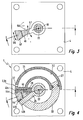
- the first rotary drive unit 2 contains a first housing 4, in which there is a first housing interior 5, which at least partially has a circular outline.
- An output shaft extends through the first housing 4 6, which is the center of the first housing interior 5 penetrates and with the one arranged in the first housing interior 5 first piston 7 is rotatably connected.
- This here first pistons designed as pivoting pistons or pivoting vanes 7 divides the first housing interior 5 into two working chambers 8, 9, in each of which the wall of the first housing 4 passes through fluid channel 12, 13, via which the fluidic pressure medium used in operation supplied or is dissipated.
- a first valve device 15 connected, which can in particular be activated electromagnetically (Figure 7). Is on a feed connection 16 of the first valve device 15 print medium on, can by appropriate Control of the first valve device 15 in each a working chamber pressure medium supplied and from each other working chamber pressure medium are discharged. This leads to a pivoting movement indicated by a double arrow 17 of the first piston 7, which is a simultaneous rotary movement 18 again indicated by a double arrow the output shaft 6 has the consequence.
- the axis of rotation be referred to as the central axis 22 and coincides with the longitudinal axis the output shaft 6 together.
- the output shaft 6 can optionally be positioned in two end positions. These end positions are in the embodiment by two lying in the swivel path of the first piston 7 Fixed end stops 24 specified the pivot path limit the first piston 7. Are in the embodiment the end stops 24 directly from the end walls of the two working chambers 8, 9 formed. However, it can also act as separate slings.
- variable end positions of the output shaft one or both end stops 24 relative to the first Housing 4 may be adjustable. Then there are too Means are available that fix the end stops 24 enable in the respectively set position.
- Adjustable end stops are shown in dot-dash lines in FIG 24 'indicated. These can deviate from the representation End stops also effective outside the working chambers 8, 9 be and have, for example, a structure such as that in the DE 19511488 C2 is described.
- the second rotary drive unit 3 is located on the second Axial side 26 of the first housing 4 and sits there, with respect the central axis 22 freely rotatable, on the output shaft 6th
- the second rotary drive unit 3 has a second housing 27, which has the shape of a longitudinal section has a torus. The radius of curvature lies on the central axis 22. Via a first bearing part 28, which is the output shaft 6 concentrically encloses the second housing 27 the output shaft 6 rotatably mounted.
- the second housing 27 defines a second housing interior 32, which follows the shape of the torus section and the closed at one end and open at the other.
- the first bearing part 28 engages in particular in the closed area In the end. Dive through the open end one designed according to the length section of a ring plunger-like second piston 33 in the second housing space 32 and thus delimits a curved working chamber 34, the length of which depends on how far the second piston 33 in immerses the second housing interior 32.
- the second piston 33 At its rear end, opposite to that in the second housing 27 engaging end, is the second piston 33 via a second bearing part 35 also on the output shaft 6, rotatable relative to this, stored.
- the first bearing part 28 also has the second bearing part 35 via an annular bearing section coaxial with the output shaft 6 36th
- the second housing 27 and the second piston 33 are relative rotatable relative to one another about the central axis 22. You can also independently of one another, again about the central axis 22, relative to the first housing 4 of the first rotary drive unit 2 be twisted.
- a fluid channel 37 which is connected via a fluid line 38 is connected to a second valve device 42.
- this can expediently be activated electrically. she can be placed in two switch positions, one in Figure 7 emerging first switching position a pressure source P is switched through, so that the working chamber 34 with Media is applied. In a second switch position the working chamber 34 is depressurized.
- the second housing 27 and the second piston 33 are each a first or second driver 43a, 43b is provided which participates in the rotary movement of the respective component.
- the carriers 43a, 43b can, for example, in a structural unit with the two bearing parts 28, 35 are executed. To those in the The two have sides facing each other Carriers 43a, 43b each have a carrier surface 44a, 44b.
- the coupling member 45 can be angled in an L-shape. Becomes the output shaft 6 through the first rotary drive 2 to one Driven rotary motion, guides the motion-coupled coupling member 45 a corresponding one, indicated by a double arrow Pivotal movement 47 around the central axis 22. In reverse Way leads to one exerted on the coupling member 45 Torque that the coupling member 45 pivots and thus the associated output shaft 6 is rotated.
- the rotary drive 1 also has an intermediate position stop 48, which between the coupling member 45 the two drivers 43a, 43b protrude. He is regarding the first housing 4 fixed.
- the intermediate position stop is seated 48 with an annular bearing section 52 freely rotatable on the output shaft 6 and contains a radially connected to the bearing portion 52 protruding, angled stop arm 53 in the adjustment path of the two drivers 43a, 43b protrudes.
- Fastening means 54 indicated by dash-dotted lines is the stop arm 53 attached to the first housing 4 so that it is this can not be rotated about the central axis 22 can.
- the intermediate stop 48 takes one certain intermediate position default position, depending on Embodiment of the rotary drive an unchangeable default position or is a variable default position.
- an unchangeable default position or is a variable default position.
- Central axis 22 is rotatable and gradually in different Default positions with respect to the first Housing 44 can be fixed, such default positions being exemplary are indicated by points at 56.
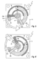
- the second rotary drive unit by corresponding actuation of the second valve device 42 is depressurized so that it is in a freewheeling state occupies in the trapped without disability Compressed air a relative twisting between the second housing 27 and the second piston 33 is possible.
- the first piston 7 pivoted in one direction or the other, the output shaft 6 performs a rotary movement, the also moving coupling member 45 on the upstream in the direction of rotation Driver 43a or 43b acts and this before pushes itself.
- the first rotary drive unit 2 In order to obtain the desired intermediate position of the output shaft 6, becomes the first rotary drive unit 2 in turn depressurized, so that now they are in a freewheeling state occupies the first piston 7 and thus the output shaft 6 gives free rotation with respect to the first housing 4.
- the free running state of the first rotary drive unit 2 results in the embodiment by switching the second valve device 42 into that shown in FIG first switching position, since the feed connection 16 via a supply line 57 connected to the second valve device 42 is and is therefore controlled by this.
- the second rotary drive unit 3 fed with pressure medium so that it is in one Positioning state. This means that through the Pressurizing the working chamber 34 the second housing 27 and the second piston 33 perform a relative movement, within which the two drivers 43a, 43b are like pliers approach each other. The movement of the respective driver 43a, 43b stops the moment he hits the intermediate stop 48 accumulates.
- the coupling member 45 With this forceps movement, the coupling member 45 becomes one Carrier loaded and pushed in front of him, in whose travel range is currently protruding.
- the rotational movement of the coupling member 45 ends when both drivers 43a, 43b with their mutually facing driver surfaces 44a, 44b of opposite Sides against the intermediate position stop 48 and at the same time the coupling member 45 between them hold.
- a big advantage of the rotary drive is that each of the three positions as part of a continuous movement approached from any position previously assumed can be unlocked without prior mechanical unlocking of any components and without that a stopover of the movement would be required.
- the two valve devices 15, 42 are expedient Part of an overall designated by reference number 58 Control circuit, to the expediently also one sensors not shown and an electronic Control device belongs to the movement sequences exactly on each other to be able to vote.
Landscapes
- Engineering & Computer Science (AREA)
- Physics & Mathematics (AREA)
- Fluid Mechanics (AREA)
- Mechanical Engineering (AREA)
- General Engineering & Computer Science (AREA)
- Chemical & Material Sciences (AREA)
- Analytical Chemistry (AREA)
- Actuator (AREA)
Abstract
Description
- mit einer ersten Drehantriebseinheit, die ein erstes Gehäuse, einen relativ zum ersten Gehäuse verdrehbaren ersten Kolben und eine drehfest mit dem ersten Kolben verbundene Abtriebswelle aufweist, wobei die Abtriebswelle durch Fluidbeaufschlagung des ersten Kolbens zu einer oszillierenden Drehbewegung um eine Zentralachse zwischen zwei Endstellungen antreibbar ist,
- mit einem drehfest mit der Abtriebswelle verbundenen, bei der Drehbewegung der Abtriebswelle eine Schwenkbewegung bezüglich der Zentralachse ausführenden Kopplungsglied,
- mit einer zu der ersten Drehantriebseinheit koaxialen zweiten Drehantriebseinheit, die ein zweites Gehäuse und einen zweiten Kolben aufweist, die relativ zueinander und mit Bezug zu dem ersten Gehäuse um die Zentralachse verdrehbar sind und die jeweils einen bei der Drehbewegung eine Schwenkbewegung bezüglich der Zentralachse ausführenden Mitnehmer aufweisen,
- und mit einem bezüglich dem ersten Gehäuse ortsfesten Zwischenstellungsanschlag, der wie das Kopplungsglied zwischen die beiden Mitnehmer ragt,
- wobei die zweite Drehantriebseinheit wahlweise in einen die freie Schwenkbeweglichkeit der Mitnehmer und somit die freie Drehbarkeit der Abtriebswelle zwischen den beiden Endstellungen ermöglichenden drucklosen Freilaufzustand schaltbar ist oder in einen druckbeaufschlagten Positionierzustand, in dem die Mitnehmer sich zangenartig bis zur Anlage an dem Zwischenstellungsanschlag einander annähern, wobei durch Mitnahme des Kopplungsgliedes die mit diesem verbundene Abtriebswelle in eine zwischen den beiden Endstellungen liegende Zwischenstellung verdreht wird.
- Figur 1
- eine bevorzugte Bauform des erfindungsgemäßen Dreistellungs-Drehantriebes im Längsschnitt gemäß Schnittlinie I-I aus Figuren 2 bis 4,
- Figur 2
- einen Querschnitt durch den Drehantrieb aus Figur 1 gemäß Schnittlinie II-II aus Figur 1,
- Figur 3
- einen weiteren Querschnitt des Drehantriebes gemäß Schnittlinie III-III aus Figur 1,
- Figur 4
- erneut einen Querschnitt des Drehantriebes gemäß Schnittlinie IV-IV aus Figur 1,
- Figuren 5 und 6
- den Drehantrieb aus Figur 1 in einer Ansicht vergleichbar der Figur 4 während der Aktivierung bei unterschiedlichen Drehrichtungen, und
- Figur 7
- ein vereinfachtes Schaltbild des Drehantriebes der Figuren 1 bis 6, wobei die beiden Drehantriebseinheiten zur Vereinfachung der Erläuterung als Linearantriebe gezeichnet sind.
Claims (9)
- Fluidbetätigter Dreistellungs-Drehantrieb,mit einer ersten Drehantriebseinheit (2), die ein erstes Gehäuse (4), einen relativ zum ersten Gehäuse (4) verdrehbaren ersten Kolben (7) und eine drehfest mit dem ersten Kolben (7) verbundene Abtriebswelle (6) aufweist, wobei die Abtriebswelle (6) durch Fluidbeaufschlagung des ersten Kolbens (7) zu einer oszillierenden Drehbewegung um eine Zentralachse (22) zwischen zwei Endstellungen antreibbar ist,mit einem drehfest mit der Abtriebswelle (6) verbundenen, bei der Drehbewegung der Abtriebswelle (6) eine Schwenkbewegung bezüglich der Zentralachse (22) ausführenden Kopplungsglied,mit einer zu der ersten Drehantriebseinheit(2) koaxialen zweiten Drehantriebseinheit (3), die ein zweites Gehäuse (27) und einen zweiten Kolben (33) aufweist, die relativ zueinander und mit Bezug zu dem ersten Gehäuse (4) um die Zentralachse (22) verdrehbar sind und die jeweils einen bei der Drehbewegung eine Schwenkbewegung bezüglich der Zentralachse (22) ausführenden Mitnehmer (43a, 43b) aufweisen,und mit einem bezüglich dem ersten Gehäuse (4) ortsfesten Zwischenstellungsanschlag (48), der wie das Kopplungsglied (45) zwischen die beiden Mitnehmer (43a, 43b) ragt,wobei die zweite Drehantriebseinheit (3) wahlweise in einen die freie Schwenkbeweglichkeit der Mitnehmer (43a, 43b) und somit die freie Drehbarkeit der Abtriebswelle (6) zwischen den beiden Endstellungen ermöglichenden drucklosen Freilaufzustand schaltbar ist oder in einen druckbeaufschlagten Positionierzustand, in dem die Mitnehmer (43a, 43b) sich zangenartig bis zur Anlage an den Zwischenstellungsanschlag (48) einander annähern, wobei durch Mitnahme des Kopplungsgliedes (45) die mit diesem verbundene Abtriebswelle (6) in eine zwischen den beiden Endstellungen liegende Zwischenstellung verdreht wird.
- Drehantrieb nach Anspruch 1, dadurch gekennzeichnet, dass wenigstens eine Drehantriebseinheit (2) als Schwenkkolbenantrieb (2a) ausgebildet ist.
- Drehantrieb nach Anspruch 1 oder 2, dadurch gekennzeichnet, dass wenigstens eine Drehantriebseinheit (3) als Ringkolbenantrieb (3a) ausgebildet ist.
- Drehantrieb nach einem der Ansprüche 1 bis 3, dadurch gekennzeichnet, dass der Zwischenstellungsanschlag (48) verstellbar und in unterschiedlichen Positionen ortsfest bezüglich dem ersten Gehäuse (4) fixierbar ist.
- Drehantrieb nach Anspruch 4, dadurch gekennzeichnet, dass der Zwischenstellungsanschlag (48) frei drehbar auf der Abtriebswelle (6) sitzt und einen von dieser wegragenden Anschlagarm (53) aufweist, der bezüglich dem ersten Gehäuse (4) lösbar fixierbar ist.
- Drehantrieb nach einem der Ansprüche 1 bis 5, dadurch gekennzeichnet, dass sowohl das zweite Gehäuse (27) als auch der zweite Kolben (33) frei drehbar auf der Abtriebswelle (6) gelagert sind.
- Drehantrieb nach einem der Ansprüche 1 bis 6, gekennzeichnet durch eine Ansteuerschaltung (58) durch die die zweite Drehantriebseinheit (3) wahlweise in den Freilaufzustand oder den Positionierzustand versetzbar ist und durch die die erste Drehantriebseinheit (2) während des Positionierzustandes der zweiten Drehantriebseinheit (3) ihrerseits in einen die freie Beweglichkeit der Abtriebswelle (6) gewährleistenden drucklosen Freilaufzustand schaltbar ist.
- Drehantrieb nach Anspruch 7, dadurch gekennzeichnet, dass die Ansteuerschaltung (58) mindestens eine Ventileinrichtung (15, 42) enthält.
- Drehantrieb nach einem der Ansprüche 1 bis 8, dadurch gekennzeichnet, dass zur Vorgabe variabler Endstellungen der Abtriebswelle (6) wenigstens ein verstellbarer und in unterschiedlichen Positionen ortsfest bezüglich dem ersten Gehäuse (4) fixierbarer Endanschlag (24, 24') vorgesehen ist.
Applications Claiming Priority (2)
| Application Number | Priority Date | Filing Date | Title |
|---|---|---|---|
| DE20219367U DE20219367U1 (de) | 2002-12-13 | 2002-12-13 | Fluidbetätigter Dreistellungs-Drehantrieb |
| DE20219367U | 2002-12-13 |
Publications (2)
| Publication Number | Publication Date |
|---|---|
| EP1429037A1 true EP1429037A1 (de) | 2004-06-16 |
| EP1429037B1 EP1429037B1 (de) | 2005-11-23 |
Family
ID=7977964
Family Applications (1)
| Application Number | Title | Priority Date | Filing Date |
|---|---|---|---|
| EP20030024778 Expired - Lifetime EP1429037B1 (de) | 2002-12-13 | 2003-10-30 | Fluidbetätigter Dreistellungs-Drehantrieb |
Country Status (2)
| Country | Link |
|---|---|
| EP (1) | EP1429037B1 (de) |
| DE (2) | DE20219367U1 (de) |
Cited By (7)
| Publication number | Priority date | Publication date | Assignee | Title |
|---|---|---|---|---|
| EP1896730A4 (de) * | 2005-06-30 | 2010-03-24 | James Antony Kells | Toroidzylinderbetätigungsvorrichtung |
| CN107002722A (zh) * | 2014-09-19 | 2017-08-01 | 伍德沃德有限公司 | 旋转活塞促动器防旋转构造 |
| US10030679B2 (en) | 2013-02-27 | 2018-07-24 | Woodward, Inc. | Rotary piston type actuator |
| US10458441B2 (en) | 2013-02-27 | 2019-10-29 | Woodward, Inc. | Rotary piston actuator anti-rotation configurations |
| US10767669B2 (en) | 2013-02-27 | 2020-09-08 | Woodward, Inc. | Rotary piston type actuator with a central actuation assembly |
| US11199248B2 (en) | 2019-04-30 | 2021-12-14 | Woodward, Inc. | Compact linear to rotary actuator |
| US11333175B2 (en) | 2020-04-08 | 2022-05-17 | Woodward, Inc. | Rotary piston type actuator with a central actuation assembly |
Citations (4)
| Publication number | Priority date | Publication date | Assignee | Title |
|---|---|---|---|---|
| DE871557C (de) * | 1945-08-24 | 1953-03-23 | Von Roll Ag | Gelenklose, hydraulische Ringkolben-Antriebseinrichtung |
| US2974645A (en) * | 1957-10-15 | 1961-03-14 | Allmama Svenska Elek Ska Aktie | Hydraulic servo-motors |
| JPH034004A (ja) * | 1989-05-31 | 1991-01-10 | Akashi Seisakusho Co Ltd | ロータリアクチュエータ |
| DE4124273A1 (de) * | 1990-07-31 | 1992-02-06 | Kuroda Precision Ind Ltd | Spannvorrichtung mit mehrstufenoeffnung |
Family Cites Families (2)
| Publication number | Priority date | Publication date | Assignee | Title |
|---|---|---|---|---|
| DE8217034U1 (de) | 1982-06-15 | 1983-06-23 | Habermann, Rudi, 5657 Haan | Vorschubeinrichtung |
| DE3941255C2 (de) | 1989-12-14 | 1994-02-03 | Festo Kg | Fluidbetätigter Schwenkkolbenmotor |
-
2002
- 2002-12-13 DE DE20219367U patent/DE20219367U1/de not_active Expired - Lifetime
-
2003
- 2003-10-30 DE DE50301729T patent/DE50301729D1/de not_active Expired - Lifetime
- 2003-10-30 EP EP20030024778 patent/EP1429037B1/de not_active Expired - Lifetime
Patent Citations (4)
| Publication number | Priority date | Publication date | Assignee | Title |
|---|---|---|---|---|
| DE871557C (de) * | 1945-08-24 | 1953-03-23 | Von Roll Ag | Gelenklose, hydraulische Ringkolben-Antriebseinrichtung |
| US2974645A (en) * | 1957-10-15 | 1961-03-14 | Allmama Svenska Elek Ska Aktie | Hydraulic servo-motors |
| JPH034004A (ja) * | 1989-05-31 | 1991-01-10 | Akashi Seisakusho Co Ltd | ロータリアクチュエータ |
| DE4124273A1 (de) * | 1990-07-31 | 1992-02-06 | Kuroda Precision Ind Ltd | Spannvorrichtung mit mehrstufenoeffnung |
Non-Patent Citations (1)
| Title |
|---|
| PATENT ABSTRACTS OF JAPAN vol. 015, no. 109 (M - 1093) 15 March 1991 (1991-03-15) * |
Cited By (10)
| Publication number | Priority date | Publication date | Assignee | Title |
|---|---|---|---|---|
| EP1896730A4 (de) * | 2005-06-30 | 2010-03-24 | James Antony Kells | Toroidzylinderbetätigungsvorrichtung |
| US7895935B2 (en) | 2005-06-30 | 2011-03-01 | James Antony Kells | Toroidal ram actuator |
| US10030679B2 (en) | 2013-02-27 | 2018-07-24 | Woodward, Inc. | Rotary piston type actuator |
| US10458441B2 (en) | 2013-02-27 | 2019-10-29 | Woodward, Inc. | Rotary piston actuator anti-rotation configurations |
| US10767669B2 (en) | 2013-02-27 | 2020-09-08 | Woodward, Inc. | Rotary piston type actuator with a central actuation assembly |
| CN107002722A (zh) * | 2014-09-19 | 2017-08-01 | 伍德沃德有限公司 | 旋转活塞促动器防旋转构造 |
| US11199248B2 (en) | 2019-04-30 | 2021-12-14 | Woodward, Inc. | Compact linear to rotary actuator |
| US11927249B2 (en) | 2019-04-30 | 2024-03-12 | Woodward, Inc. | Compact linear to rotary actuator |
| US12270461B2 (en) | 2019-04-30 | 2025-04-08 | Woodward, Inc. | Compact linear to rotary actuator |
| US11333175B2 (en) | 2020-04-08 | 2022-05-17 | Woodward, Inc. | Rotary piston type actuator with a central actuation assembly |
Also Published As
| Publication number | Publication date |
|---|---|
| EP1429037B1 (de) | 2005-11-23 |
| DE20219367U1 (de) | 2003-02-13 |
| DE50301729D1 (de) | 2005-12-29 |
Similar Documents
| Publication | Publication Date | Title |
|---|---|---|
| DE2634066C3 (de) | Vorrichtung für den Vor- und Rücklauf von selbstangetriebenen, pneumatischen Rammbohrgeräten | |
| EP0352436B1 (de) | Vorrichtung zur relativen Winkelverstellung zwischen zwei in Antriebsverbindung stehenden Wellen | |
| DE102018204361B3 (de) | Mehrwegeventil und Verfahren zu seinem Betreiben | |
| EP0933527B1 (de) | Fluidbetätigte Drehantriebsvorrichtung | |
| DE2617610A1 (de) | Kraftbetaetigtes drehmoment-werkzeug | |
| DE3032554C2 (de) | ||
| EP0911530B1 (de) | Dreh-Linear-Einheit | |
| EP1429037B1 (de) | Fluidbetätigter Dreistellungs-Drehantrieb | |
| EP0208827A1 (de) | Greifvorrichtung | |
| EP3720615B1 (de) | Vorrichtung zum auftragen eines viskosen materials auf werkstücke | |
| DE3545858C1 (de) | Servosteuerung,insbesondere Servolenkung fuer Kraftfahrzeuge | |
| AT407280B (de) | Einrichtung zum verstellen des hubes von fluidgesteuerten schlageinrichtungen | |
| DE102010050612B4 (de) | Drehantriebsvorrichtung | |
| DE1160318B (de) | Hilfskraftlenkeinrichtung, insbesondere fuer Kraftfahrzeuge | |
| DE3811110A1 (de) | Kolbenantrieb | |
| DE1775857B2 (de) | Keilriemenwechselgetriebe | |
| EP0554537B1 (de) | Axialkolbenmaschine, insbes. Hydropumpe der Schiefscheibenbauart oder der Schrägachsenbauart, deren Durchsatzvolumen durch eine Einstellvorrichtung einstellbar ist | |
| EP1703144B1 (de) | Fluidbetätigter Linearantrieb | |
| DE2631705A1 (de) | Steuervorrichtung fuer ein linear verschiebbares element | |
| DE1290840B (de) | Druckmittelbetaetigter Scheibenwischermotor, insbesondere fuer Kraftfahrzeuge | |
| DE102015210129A1 (de) | Hydraulisches Ventil mit verstellbarer Rastvorrichtung | |
| DE20315087U1 (de) | Drehantriebsvorrichtung | |
| EP1310388B1 (de) | Niveauregelventil zum selbsttägigen Konstanthalten der Fahrzeughöhe eines Nutzfahrzeuges mit Luftfederung | |
| DE976712C (de) | Steuereinrichtung mit hydraulisch entlastetem Drehschieber | |
| DE102010005526A1 (de) | Drehantriebsvorrichtung |
Legal Events
| Date | Code | Title | Description |
|---|---|---|---|
| PUAI | Public reference made under article 153(3) epc to a published international application that has entered the european phase |
Free format text: ORIGINAL CODE: 0009012 |
|
| 17P | Request for examination filed |
Effective date: 20040405 |
|
| AK | Designated contracting states |
Kind code of ref document: A1 Designated state(s): AT BE BG CH CY CZ DE DK EE ES FI FR GB GR HU IE IT LI LU MC NL PT RO SE SI SK TR |
|
| AX | Request for extension of the european patent |
Extension state: AL LT LV MK |
|
| 17Q | First examination report despatched |
Effective date: 20040727 |
|
| AKX | Designation fees paid |
Designated state(s): DE FR GB IT |
|
| GRAP | Despatch of communication of intention to grant a patent |
Free format text: ORIGINAL CODE: EPIDOSNIGR1 |
|
| GRAS | Grant fee paid |
Free format text: ORIGINAL CODE: EPIDOSNIGR3 |
|
| GRAA | (expected) grant |
Free format text: ORIGINAL CODE: 0009210 |
|
| AK | Designated contracting states |
Kind code of ref document: B1 Designated state(s): DE FR GB IT |
|
| PG25 | Lapsed in a contracting state [announced via postgrant information from national office to epo] |
Ref country code: IT Free format text: LAPSE BECAUSE OF FAILURE TO SUBMIT A TRANSLATION OF THE DESCRIPTION OR TO PAY THE FEE WITHIN THE PRESCRIBED TIME-LIMIT;WARNING: LAPSES OF ITALIAN PATENTS WITH EFFECTIVE DATE BEFORE 2007 MAY HAVE OCCURRED AT ANY TIME BEFORE 2007. THE CORRECT EFFECTIVE DATE MAY BE DIFFERENT FROM THE ONE RECORDED. Effective date: 20051123 |
|
| REG | Reference to a national code |
Ref country code: GB Ref legal event code: FG4D Free format text: NOT ENGLISH |
|
| GBT | Gb: translation of ep patent filed (gb section 77(6)(a)/1977) | ||
| REF | Corresponds to: |
Ref document number: 50301729 Country of ref document: DE Date of ref document: 20051229 Kind code of ref document: P |
|
| ET | Fr: translation filed | ||
| PLBE | No opposition filed within time limit |
Free format text: ORIGINAL CODE: 0009261 |
|
| STAA | Information on the status of an ep patent application or granted ep patent |
Free format text: STATUS: NO OPPOSITION FILED WITHIN TIME LIMIT |
|
| 26N | No opposition filed |
Effective date: 20060824 |
|
| PGFP | Annual fee paid to national office [announced via postgrant information from national office to epo] |
Ref country code: DE Payment date: 20101007 Year of fee payment: 8 |
|
| PGFP | Annual fee paid to national office [announced via postgrant information from national office to epo] |
Ref country code: GB Payment date: 20101001 Year of fee payment: 8 Ref country code: IT Payment date: 20101029 Year of fee payment: 8 |
|
| PGFP | Annual fee paid to national office [announced via postgrant information from national office to epo] |
Ref country code: FR Payment date: 20111103 Year of fee payment: 9 |
|
| GBPC | Gb: european patent ceased through non-payment of renewal fee |
Effective date: 20121030 |
|
| REG | Reference to a national code |
Ref country code: FR Ref legal event code: ST Effective date: 20130628 |
|
| PG25 | Lapsed in a contracting state [announced via postgrant information from national office to epo] |
Ref country code: GB Free format text: LAPSE BECAUSE OF NON-PAYMENT OF DUE FEES Effective date: 20121030 Ref country code: DE Free format text: LAPSE BECAUSE OF NON-PAYMENT OF DUE FEES Effective date: 20130501 |
|
| REG | Reference to a national code |
Ref country code: DE Ref legal event code: R119 Ref document number: 50301729 Country of ref document: DE Effective date: 20130501 |
|
| PG25 | Lapsed in a contracting state [announced via postgrant information from national office to epo] |
Ref country code: FR Free format text: LAPSE BECAUSE OF NON-PAYMENT OF DUE FEES Effective date: 20121031 Ref country code: IT Free format text: LAPSE BECAUSE OF NON-PAYMENT OF DUE FEES Effective date: 20121030 |