EP1426203A1 - Organe de suspension, timonerie de direction et méthode fournissant un empattement variable - Google Patents
Organe de suspension, timonerie de direction et méthode fournissant un empattement variable Download PDFInfo
- Publication number
- EP1426203A1 EP1426203A1 EP02445164A EP02445164A EP1426203A1 EP 1426203 A1 EP1426203 A1 EP 1426203A1 EP 02445164 A EP02445164 A EP 02445164A EP 02445164 A EP02445164 A EP 02445164A EP 1426203 A1 EP1426203 A1 EP 1426203A1
- Authority
- EP
- European Patent Office
- Prior art keywords
- ball joint
- steering
- wheel
- lever arm
- arrangement according
- Prior art date
- Legal status (The legal status is an assumption and is not a legal conclusion. Google has not performed a legal analysis and makes no representation as to the accuracy of the status listed.)
- Granted
Links
Images


Classifications
-
- B—PERFORMING OPERATIONS; TRANSPORTING
- B60—VEHICLES IN GENERAL
- B60G—VEHICLE SUSPENSION ARRANGEMENTS
- B60G7/00—Pivoted suspension arms; Accessories thereof
-
- B—PERFORMING OPERATIONS; TRANSPORTING
- B60—VEHICLES IN GENERAL
- B60G—VEHICLE SUSPENSION ARRANGEMENTS
- B60G3/00—Resilient suspensions for a single wheel
- B60G3/18—Resilient suspensions for a single wheel with two or more pivoted arms, e.g. parallelogram
- B60G3/20—Resilient suspensions for a single wheel with two or more pivoted arms, e.g. parallelogram all arms being rigid
-
- B—PERFORMING OPERATIONS; TRANSPORTING
- B62—LAND VEHICLES FOR TRAVELLING OTHERWISE THAN ON RAILS
- B62D—MOTOR VEHICLES; TRAILERS
- B62D9/00—Steering deflectable wheels not otherwise provided for
-
- B—PERFORMING OPERATIONS; TRANSPORTING
- B60—VEHICLES IN GENERAL
- B60G—VEHICLE SUSPENSION ARRANGEMENTS
- B60G2200/00—Indexing codes relating to suspension types
- B60G2200/10—Independent suspensions
- B60G2200/14—Independent suspensions with lateral arms
- B60G2200/156—Independent suspensions with lateral arms wishbone-type arm formed by two links defining a virtual apex
Definitions
- the invention relates to an arrangement and a method for wheel track adjustment for steerable wheels in a vehicle, in order to provide a turning circle radius reduction and improved cornering stability.
- Modern passenger vehicles over a certain size are often provided with relatively large diameter wheels, which can give increased ride comfort and an improved fuel economy.
- wider front drivetrain systems usually in the form of transverse mounted engines, while the vehicle body has to remain as narrow as possible for aerodynamic reasons.
- the available space for the wheels is decreased, which in turn decreases the maximum possible steering angle of the front wheels.
- vehicles with longer wheel bases often, but not necessarily, combined with a transverse mounted engine. This arrangement increases the available interior passenger space and improves ride comfort.
- a long wheel base also increases the turning circle radius and may the problems caused by wheel size and drivetrain placement.
- a known solution to the above problems is the use of four-wheel steering.
- this requires steerable rear wheels, which adds weight and complexity to the rear wheel suspension.
- Such a system also requires some form of computer control, as the steering behaviour of the rear wheels must be varied in both magnitude and direction depending on vehicle speed and other parameters.
- a further known solution involves braking the inside front wheel when turning at low speed. This will reduce the turning circle radius, but at the cost of increased tire wear. The maximum steering angle is not affected by this solution.
- the arrangement will also require anti-locking brakes that can be computer controlled to brake individual wheels.
- a solution that allows the pivot position of the wheels to be adjusted to avoid interference with body components is known from GB 2 110 173-A.
- This arrangement discloses a mechanical linkage connecting the steerable wheels in such a way that the wheels are prevented from coming into contact with the outer fairing of the vehicle.
- the wheel track is reduced during turning and cornering. Especially when cornering, a reduced wheel track may affect the handling characteristics of the vehicle.
- the invention relates to a method for wheel track adjustment for a steerable vehicle wheel arrangement.
- the arrangement includes a steering actuator and a steering actuating mechanism for transferring steering movements from the steering actuator to a wheel hub.
- the steering actuating mechanism includes a controllable lever arm having a pivot on a suspension control arm, which control arm is pivotably attached to the vehicle at a first end and is provided with a ball joint that is pivotably attached to a wheel hub at a second end.
- a pair of connecting rods are pivotably connected to the lever arm on opposite sides of the pivot of the lever arm and to the wheel hub on opposite sides of the ball joint.
- the lever arm is controlled by a steering actuation mechanism and causes the connecting rods to displace the ball joint a predetermined distance along an axis substantially transverse to a central longitudinal axis of the vehicle, which distance is proportional to a vehicle wheel steering angle.
- the displacement of the ball joints increases as the steering angle is increased.
- actuation of the lever arm causes the connecting rods to displace the ball joint in a direction away from the central longitudinal axis. In this way the vehicle wheel track is increased, in order to allow a increased steering angle and improve road handling during cornering.
- the ball joint of an inner wheel is displaced a greater distance than an outer wheel.
- the inner and outer wheels will be placed at different radii relative to an imaginary centre point. In order to reduce tyre wear it is advantageous to give the inner wheel a correspondingly greater steering angle.
- a wheel track adjustment arrangement for a steerable vehicle wheel to be used according to the above method is part of both the suspension and the steering linkage of the vehicle.
- the suspension arrangement includes a first control arm having an inner end attached to the vehicle and pivotable around an axis substantially parallel to a longitudinal axis of the vehicle and an outer end pivotably connected to a wheel hub via a ball joint.
- the first control arm is preferably arranged as a lower control arm, whereby the suspension may be provided with a second, upper control arm attached between the vehicle and the wheel hub.
- a further suspension member may be attached between the vehicle and the wheel hub and arranged to suspend the vehicle and dampen vertical movement of said vehicle wheel.
- This further suspension member may be a standard spiral spring and telescopic damper arrangement, or any other type of pneumatic or hydraulic damper.
- the suspension preferably includes a damper arrangement, while the second control arm is optional.
- the ball joint is displaceable a predetermined distance along an axis substantially transverse to the longitudinal direction of the vehicle, which distance is proportional to a vehicle wheel steering angle.
- the ball joint is arranged to be axially slidable relative to the control arm.
- the ball joint is slidably attached to the control arm.
- the ball joint and its attachment part may be secured to an outer surface of the control arm, or be placed in a cavity therein.
- the ball joint may also be attached directly onto the control arm, whereby the control arm itself may have a moving part, such as a telescoping section
- the slidable attachment may be achieved by a number of different means.
- the ball joint may be slidably suspended in one or more rubber or elastomeric bushings, surrounding the attachment part wholly or in part.
- the bushing or bushings may be attached onto the attachment part or to the inner surface of the cavity in the control arm. This arrangement allows the ball joint and its attachment part to slide freely in the transverse direction of the vehicle. At the same time the resilient bushings allow a degree of movement perpendicular to said direction.
- the displacement of the ball joint is controlled by a pair of substantially parallel connecting rods pivotably attached to the vehicle wheel hub on either side of the ball joint.
- the connecting rods are pivotably attached to and controlled by a common lever arm that is pivotably attached to the control arm.
- the connecting rods have a length between their respective pivots that exceeds the distance between the pivot of the lever arm and the ball joint.
- Said lever arm is controlled by a vehicle steering gear actuator.
- the combination of a resilient attachment and parallel connecting rods will contribute to an enhanced compliance of the suspension in the longitudinal direction of the vehicle.
- the resilient bushing will allow the ball joint and wheel hub to yield in the longitudinal direction when the tyre encounters an obstacle, such as a transverse tarmac edge. This will contribute to a more comfortable ride.
- the movement of the ball joint is controlled by the connecting rods during actuation of the steering gear, so that the greatest displacement of the ball joint occurs at the maximum steering angle of the vehicle wheel.
- the displacement of the ball joint causes an increase of the wheel track.
- the shape of the lever arm and the positions of the pivots of the connecting rods at the hub and the lever arm are symmetrically placed on either side of a vertical plane through the ball joint and the pivot of the lever arm.
- the ball joint of an inner wheel may be displaced a greater distance than an outer wheel. This is caused by the inner and outer wheels turning on different radii, as described above.
- this is achieved by means of a so-called Ackerman steering.
- Ackerman steering This is a double-pivoting steering system where the outer ends of the steering arms are bent slightly inward so that when the vehicle is making a turn, the inside wheel will turn more sharply than the outer wheel. This is done to compensate for the greater distance the outside wheel must travel due to the difference in turning radii between the inner and the outer wheel.
- the steering arms act on their respective lever arm, the above shape of said steering arms causes the inner wheel to turn through a greater steering angle than the outer wheel.
- the symmetrical arrangement of the lever arm and connecting rods will consequently displace the inner ball joint further out than the outer ball joint.
- the linkage described above can be made slightly asymmetrical. This can be achieved by altering the length of either of the connecting rods between their respective pivots. For instance, by extending the front connecting rods and their associated section of the lever arm, as seen in the main direction of travel of the vehicle, a suitable distance, the ball joint attached to the inner wheel would be pushed further out. Obviously, the same effect could be achieved by shortening the rear connecting rods and their associated section of the lever arm. An equal actuation of the lever arms on either side will then cause a greater steering angle for the inner wheel, accompanied by a corresponding greater displacement of the inner ball joint. This arrangement does not have to depend on the Ackerman steering principle to achieve unequal steering angles for the inner and outer wheels.
- the attachment points of the ball joint and the connecting rods ensures that the displacement of the ball joint also causes an adjustment of the camber angle of the vehicle wheel.
- the ball joint is preferably attached to a suspension control arm and is attached to the wheel hub below an attachment point for a further control arm or suspension member. If the hub is supported by the lower control arm and a dampening suspension member, an outward displacement of the ball joint will pivot the wheel hub around a pivot located at a pivotable attachment point for the upper end of the suspension member. If the hub is additionally supported by an upper control arm, an outward displacement of the ball joint will instead pivot the wheel hub around a pivot located at a pivotable attachment point for the inner end of the upper control arm.
- the increase in the camber angle is dependent on the distance between the ball joint and said attachment point of said further control arm or suspension member at the vehicle. In addition to the improved stability caused by the increased wheel track, this will have a positive effect on the dynamic handling of the vehicle during cornering. Especially for the outer wheel, this negative camber will counteract the tendency towards positive camber caused by the rolling movement of the vehicle during cornering or turning.
- the steering linkage arrangement includes an actuating mechanism, the above mentioned controllable lever arm having a pivot on the suspension control arm, which control arm is pivotably attached to the vehicle at a first end and is provided with a ball joint that is pivotably attached to a wheel hub at a second end, and where a pair of connecting rods are pivotably connected to the lever arm on opposite sides of the pivot and to the wheel hub on opposite sides of the ball joint.
- the actuating mechanism When the actuating mechanism is operated, the ball joint is displaced a predetermined distance along an axis substantially transverse to the longitudinal direction of the vehicle, which distance is proportional to a vehicle wheel steering angle.
- the lever arm is preferably positioned so that an axis substantially transverse to the longitudinal axis of the vehicle intersects both the ball joint and the pivot of the lever arm.
- the actuating mechanism may comprise a steering arm actuated by a servo steering mechanism, which steering arm is then connected to the lever arm.
- the lever arm may be controlled by an electric or a hydraulic motor.
- said motor may actuate the lever arm directly or via a steering arm. The latter arrangement would be preferable for a steer-by-wire vehicle, where an electronic control unit could control each motor individually to achieve the desired effect.
- the steering actuator acts on the wheel hub at a position horizontally displaced from the ball joint in a plane parallel to the wheel hub.
- the steering actuator can act on one end of a controllable lever arm having a pivot on the suspension control arm.
- the controllable lever arm acts on a connecting rod pivotably connected between the other end of the lever arm, at on the opposite side of the pivot, and the wheel hub via the ball joint.
- the ball joint is mounted on the control arm by means of an elastic bushing that allows for both rotation and axial displacement of the ball joint at the end of the connecting rod.
- the steering actuator can act on one end of an intermediate controllable lever arm having a pivot on the suspension control arm.
- the intermediate lever arm is provided with a teeth along a circular segment, in order to transmit a rotary motion to a gear wheel.
- a connecting rod is pivotably attached between the periphery of said gear wheel and the ball joint, so that rotation of the gear wheel causes a displacement of the ball joint.
- the ball joint is attached to the end of a hydraulic actuator that controls the movement of the ball joint in response to the steering input from the driver. If the steering actuator is hydraulically operated, hydraulic pressure from said steering actuator may be used to actuate the hydraulic actuator attached to said ball joint. (Fig.7)
- connecting rod or rods and/or the lever arm can alternatively be replaced by screw drives or hydraulic or pneumatic cylinders of equal or differing stroke, depending on the desired effect with respect to turning radius for opposing wheels.
- Such drives or cylinders may be attached to the control arm and the wheel hub at pivoting points corresponding to those of the connecting rod or rods, when the hub is aligned with the longitudinal axis of the vehicle.
- An electronic control means may be used for individual control of the respective devices.
- the solution according to the invention allows the turning circle radius to be reduced by moving the pivots of the wheels away from interfering components, thereby allowing for larger steering angles. By allowing differentiated steering angles the turning circle radius can be further reduced. In addition, the displacement of the wheels, when turned, gives a wider wheel track for the steerable wheels, which improves handling of the vehicle during cornering. Hence the above solution has a positive effect on both the turning circle radius and the dynamic handling of the vehicle.
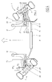
- Figure 1 shows a suspension arrangement comprising a wheel 1 including a tyre and a rim mounted on an outer part of a hub 2.
- the outer hub part 2 is rotatable, while an inner part 3 is non-rotatable.
- the outer hub part 2 is preferably, but not necessarily, provided with a brake disc 4 for co-operation with a brake caliper arrangement (not shown).
- the inner part of the hub 3 is provided with an attachment part 5 for a damper arrangement 6 of the McPherson type. This damper arrangement is pivotably attached both to the hub, at its lower end 6a, and to the vehicle, at its upper end 6b.
- the example shown illustrates a steerable, driven front wheel arrangement, whereby the inner part of the hub 3 is provided with an attachment 7 for a drive shaft 8.
- the outer part of the drive shaft 8 passes through said attachment 7 to drive the outer hub part 2, while the inner part of the drive shaft 8 is connected to the vehicle transmission (not shown) via a further attachment 9.
- the inner part of the hub 3 is further connected to a suspension control arm 10 by means of a first ball joint 11.
- the control arm 10 is attached to the vehicle at an inner pivot 12 and is placed substantially parallel to the central longitudinal axis X of the vehicle.
- the outer pivot of the control arm 10 is the ball joint 11, which is attached to the inner part of the hub 3 at position below the rotary axis Y of the hub 2, 3 and in a vertical plane through said rotary axis Y.
- a substantially vertical axis Z through the first ball joint 11 constitutes the pivot of the steerable vehicle wheel.
- the wheel is controlled by a steering gear arrangement that will be described with reference to Figure 2.
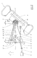
- This figure shows a front view of the embodiment of Figure 1 and where the drive shaft and damper have been removed for reasons of clarity.
- the hub is indicated in broken lines for the same reason.
- the steering gear arrangement comprises a servo cylinder 13 that when actuated causes a central rod 14 to act on a pair of steering linkages on either side of the vehicle.
- the rod acts on an intermediate steering rod 15, which is pivotably attached to the central rod 14 at an inner pivot 16 and to a steering arm 17 at an outer pivot 18.
- the central rod 14 is positioned transversely, while the steering arm 17 is positioned substantially parallel relative to the longitudinal axis of the vehicle.
- the steering rod 15 connecting the two is placed at angle in a direction outward and forward relative to the central longitudinal axis of the vehicle, thereby creating an Ackerman steering geometry.
- the steering arm 17 is pivotably attached to the control arm 10 at a first pivot 19 and controls the pivoting movement of a lever arm 20.
- the servo cylinder 13 may be replaced by an electric or hydraulic motor acting on the steering arm 17 or directly on the lever arm 10.
- the lever arm 20 is generally V-shaped with legs of substantially equal length and with its apex placed at said first pivot 19. Both legs extend horizontally away from the hub 2, 3 and are placed substantially symmetrical relative to a vertical plane through the axis Y of the wheel 1.
- the legs are provided with a second and third pivot 21 and 22 respectively, placed in front of and behind said vertical plane in the main direction of travel of the vehicle.
- a pair of connecting rods 23, 24 are connected between said second and third pivots 21, 22 and a pair of outer pivots 25, 26 on the inner hub part 3 on either side of the ball joint 11.
- the connecting rods 23, 24 extend substantially parallel in a horizontal plane.
- the outer pivots 25, 26 of the connecting rods 23, 24 and the central ball joint 11 are preferably placed in the same horizontal plane and on an axis parallel to the longitudinal axis of the vehicle.
- all pivots except the first pivot 19 of the lever arm 20 should allow pivoting movement in several axes, due to the movement of the suspension arrangement.
- all such joints are of the ball and socket type.
- the ball joint 11 has an attachment part 27 in the form of a rod or bar.
- the attachment part 27 is slidably mounted in a cavity 28 in the part of the control arm 10 extending outwards to the hub 2, 3.
- the slidable mounting comprises a pair of generally cylindrical bushings 29, 30 placed adjacent the inner and outer ends of said attachment part 27.
- the bushings are preferably made from a suitable rubber or elastomeric material, and are clamped, glued or vulcanised onto the attachment part 27. In order to facilitate replacement, they are preferably clamped in place in the cavity 28.
- This arrangement allows movement of the ball joint 11 in the axial direction of the rod shaped attachment part 27, as well as a small movement in any transverse direction thereof due to the compressive properties of the bushings 29, 30.
- the vehicle suspension is mainly arranged to absorb vertical movements of the vehicle wheel, this resilient mounting is particularly useful for absorbing small movements and shock loads on the vehicle wheel in the longitudinal direction of the vehicle.
- Figure 3 shows an alternative suspension arrangement, wherein an upper, second control arm 10a is provided in addition to the lower, first control arm 10.
- This upper control arm 10a is pivotable attached between the vehicle and the inner part of the wheel hub 3 at a pair of inner and outer pivots 12a, 11a respectively.
- the suspension arrangement is identical to that described in connection with Figure 2.
- an arrow indicates the main direction of travel of the vehicle.
- the axis X indicates the central longitudinal axis of the vehicle.
- the wheels 1 are shown at their maximum steering angles ⁇ I , ⁇ O at which positions they are closest to the inner sections of their respective wheel arches A I , A O .
- Actuation of the servo cylinder causes the steering linkage 14, 15, 17 to pivot the lever arm 20 and turn the respective wheel 1.
- the ball joint 11 and the adjacent pivots 25, 26 remain aligned in a first plane perpendicular to the rotary axis of the wheel 1.
- the ball joints on both sides of the vehicle will be displaced a small distance D I , D O from their equilibrium, or no-load positions in the slidable mountings 27, 29.
- the amount of movement is proportional to the respective lengths of and angle between the legs of the lever arm 20.
- the arrangement is preferably symmetrical on both sides of a vertical plane through the ball joint 11 and the pivot 19 of the lever arm 20.
- the inner and outer wheels will be placed at different radii relative to an imaginary centre point.
- this is achieved by means of the steering gear and steering rod geometry described above, using the Ackerman principle.
- the differentiating effect between the inner and outer wheels is achieved by extending the front connecting rod 23, which also entails a modification of the length of the corresponding leg and/or angle between the legs of the lever arm 20.
- the values of inner and outer steering wheel angles ⁇ I , ⁇ O are preferably selected within the ranges 35° ⁇ ⁇ I ⁇ 50° and 30° ⁇ ⁇ O ⁇ 40° respectively.
- the inner and outer displacements D I , D O of the respective ball joints are preferably selected within the ranges 8 mm > D I >15 mm and 5 mm> D I >12 mm respectively.
- the vehicle track width is increased by the combined distances of the inner and the outer displacements (D I +D O ). This contributes to an improvement in the dynamic handling of the vehicle during cornering.
- the attachment points of the ball joint 11 and the connecting rods 23, 24 ensures that the displacement of the ball joint 11 also causes an increased camber angle ⁇ I of the vehicle wheel (see Fig. 2).
- a displacement of the ball joint 11 around a pivot located at a pivotable attachment point for the upper end 6b of the suspension member The outward movement of the ball joint 11 will increase the camber angle ⁇ I of the vehicle wheel 1. This will contribute further to the improved handling characteristics during cornering.
- the pivot controlling the camber angle is instead located at the inner attachment point 12a of the upper, second control arm 10a.
- the outward movement of the ball joint 11 will increase the camber angle ⁇ 2 of the vehicle wheel 1.
- a displacement of equal size of the ball joint 11 will result in a larger camber angle ⁇ 2 compared to the previous example.
- FIG. 5 An arrow indicates the main direction of travel of the vehicle.
- the wheel 1 is shown at its maximum inner steering angle ⁇ I .
- Actuation of the servo cylinder 13 causes the steering linkage 14, 15, 16 to act on a steering connecting rod 31 pivotably connected to a pivot 18 at the outer end of the steering linkage 15 and to a pivot 32 on the hub 2, 3, in order to turn the respective wheel 1.
- the pivot 18 at said outer end of the steering linkage 15 is further connected to one end of a lever arm 33 having a first pivot 34 attached to the control arm 10.
- the lever arm 33 is generally V-shaped with legs of substantially equal length and with its apex placed at said first pivot 34.
- a first leg 35 is pivotably connected to the pivot 18 on the steering linkage and a second leg 36 is pivotably connected to a pivot 37 at the inner end of a connecting rod 38.
- the outer end of said connecting rod 38 is connected to the wheel hub 2, 3 via the ball joint 11, which is attached to the outer end of the control arm 10 by means of an elastic bushing 39.
- the first leg 35 is positioned in the general direction of the longitudinal axis of the vehicle, while the second leg is positioned at substantially right angles to said axis X in a vertical plane for a transverse axis Y through the ball joint 11.
- the connecting rod 38 extends substantially parallel to the second leg 36 and in the same vertical plane for the axis Y (see 37', 38'; indicated with dotted lines in Fig. 5).
- the steering connecting rod 31, the lever arm 33 and the connecting rod 38 are positioned substantially in the same horizontal plane.
- the lever arm 33 When the steering linkage is actuated to displace the wheel 1 to its maximum inner steering angle ⁇ I , then the lever arm 33 will be rotated an angle ⁇ I about its pivot 34.
- a suitable angle of rotation to achieve the maximum angle of rotation can be 40° ⁇ ⁇ I ⁇ 60°, preferably around 50°.
- the resilient properties of the bushing 39 are chosen to allow the outer end of the connecting rod 38 to be both rotated and displaced in the direction of the transverse Y-axis. However, movement in the longitudinal direction of the vehicle is limited and will in general only allow for shock absorption.
- a single bushing with varying properties can also be used.
- Such a bushing would be include a relatively soft material in the inner and outer regions, and a relatively hard material in the front and rear regions of said bushing.
- the total transverse displacement in this case the inner displacement D I , will be equal to the distance between the pivot 37' in the neutral position of the connecting rod 38' and the position of the rotated pivot 37 when projected onto the transverse axis Y.
- FIG. 6 An arrow indicates the main direction of travel of the vehicle.
- the wheel 1 is shown at its maximum outer steering angle ⁇ O .
- Actuation of the servo cylinder 13 causes the steering linkage 14, 15, 16 to act on a steering connecting rod 31 pivotably connected to a pivot 18 at the outer end of the steering linkage 15 and to a pivot 32 on the hub 2, 3, in order to turn the respective wheel 1.
- the pivot 18 at said outer end of the steering linkage 15 is further connected to one end of a lever arm 40 having a first pivot 41 attached to the control arm 10.
- the lever arm 40 is generally Y-shaped having a first section, or leg 42 pivotably connected to the pivot 18 on the steering linkage.
- the first pivot 41 placed in a transitional area between the first section 42 and a second section 43 having the general shape of a sector of a circle 44.
- the circular end part 44 of the second section 43 comprises a toothed arc positioned at a fixed radius r from the first pivot 41.
- the toothed arc co-operates with a gear wheel 45 that is rotatable about a substantially vertical axis 46, positioned in a vertical plane for the transverse axis Y through the ball joint 11 at right angles to a longitudinal axis X of the vehicle.
- a connecting rod 47 is pivotably attached to a second pivot 48 at the periphery of said gear wheel 45.
- the outer end of said connecting rod 47 is connected to the wheel hub 2, 3 via the ball joint 11, which is attached to the outer end of the control arm 10 by means of an elastic bushing 49.
- a central axis Z through the first and second sections 42, 43 is positioned in the general direction of the longitudinal axis of the vehicle.
- the connecting rod 47 extends substantially at right angles to the central axis Z, in the said vertical plane for the axis Y (see 47'; indicated with dotted lines in Fig. 6).
- the steering connecting rod 31, the lever arm 40 and the connecting rod 47 are positioned substantially in the same horizontal plane.
- the maximum displacement possible by means of a quarter revolution of the gear wheel is the distance the axis 46 of the gear wheel and the inner pivot 48 of the connecting rod 47, which corresponds to the inner displacement D I .
- the Ackerman-principle as described above will give a correspondingly smaller outer displacement D O , due to the smaller outer steering angle a O .
- the resilient properties of the bushing 49 are chosen to allow the outer end of the connecting rod 47 to be both rotated and displaced in the direction of the transverse Y-axis.
- FIG. 7 An arrow indicates the main direction of travel of the vehicle.
- the wheel 1 is shown at its maximum inner steering angle ⁇ I .
- Actuation of the servo cylinder 13 causes the steering linkage 14, 15, 16 to act on a steering connecting rod 31 pivotably connected to a pivot 18 at the outer end of the steering linkage 15 and to a pivot 32 on the hub 2, 3, in order to turn the respective wheel 1.
- the schematically illustrated main servo cylinder 13 is provided with a first chamber 50, a second chamber 51 and a piston 52 separating said chambers 50, 51.
- the main servo cylinder 13 is connected to an auxiliary servo cylinder 53 that controls the displacement of a connecting rod 54.
- Said first chamber 50 in the main servo cylinder is connected by a first conduit 55 to a first auxiliary chamber 56 in the auxiliary servo cylinder.
- the second chamber 51 in the main servo cylinder is connected by a second conduit 57 to a second auxiliary chamber 58 in the auxiliary servo cylinder.
- the first and second chambers 56, 58 in the auxiliary servo cylinder are separated by a piston 59, attached to the inner end of the connecting rod 54.
- the outer end of the connecting rod is attached to the ball joint 11, which is pivotably connected to the hub 2, 3 of the wheel 1 and attached to the outer end of the control arm 10 by means of an elastic bushing 60.
- the inner end 61 of the auxiliary servo cylinder 53 is attached to the inner end of the control arm 10 by means of a resilient mounting 62.
- This resilient mounting 62 is arranged to absorb vibrations caused by longitudinal and transverse movements of the connecting rod 54.
- the mounting 62 should not yield under forces induced by actuation of the auxiliary servo cylinder 53.
- the general design, as well as various embodiments, of the elastic bushing 60 has been described above.
- the dimensions of the second servo cylinder are selected to give a desired displacement of the connecting rod on both sides of the vehicle.
- the operation of the auxiliary servo cylinder and its connecting rod is dependent on the pressure of the displaced fluid in the main servo cylinder, there is no mechanical connection between the steering linkage and the connecting rod.
- the suspension arrangement for equal inner and outer displacement D I , D O .
- Figure 8 shows an alternative embodiment of the hydraulic circuits in a hydraulically operated arrangement.
- the auxiliary cylinders 53, 53' are identical to the cylinder described in Figure 7 and are provided with the same reference numerals. The only difference being that the second conduits 57, 57' have been joined and connected to a common second chamber 64, or drain by a conduit 65.
- Figure 8 shows the arrangement in its neutral non-actuated position. As the arrangement is identical but reversed on either side of a centre line through said common second chamber 64, only one side of the arrangement will be described below.
- the main servo cylinder has a through piston rod 66 provided with a first and second step 67, 68 defining a section having a reduced diameter on either side of a central section 69 in a main cavity of the servo cylinder.
- a first piston 70 Located in contact with the first step 67, that faces away from the central section 69, is a first piston 70 that is slidable relative to the reduced diameter section.
- This first piston 70 has a substantially cylindrical shape with a radially extending section 71, 72 at either end.
- the first radially extending section 71 is spring loaded towards the first step 67 adjacent the central section by means of a spring 73 located between said first radial section 71 and a first radial step 74 in the inner cavity of the servo cylinder.
- a spring 73 located between said first radial section 71 and a first radial step 74 in the inner cavity of the servo cylinder.
- the said second chamber 64 that is connected to the common conduit 65 and acts as a drain for the auxiliary cylinders.
- the second radially extending section 72 extends into a further cavity of the servo cylinder and is in contact with a second radial step 75 in the inner cavity, facing away from the central section 69.
- a separate piston 76 slidable relative to the reduced diameter section and in contact with a third radial step 77 in the inner cavity, facing towards the central section 69.
- a chamber 78 connected through the conduit 55 to the first chamber 56 of the auxiliary cylinder.
- actuation of the servo cylinder 13 causes a displacement of the through piston rod 66, for instance to the left in Figure 8.
- the first step 67 on the piston rod 66 will displace the first piston 70 to the left against the force of the spring 73.
- This displaced the second radial section 72 towards the separate piston 76 thereby compressing the fluid in the chamber 78 and forcing it into the first chamber 56 of the auxiliary cylinder.
- the second step 68' on the piston rod 66 will displace the separate piston 76' to the left.
- the second radially extending section 72' of the corresponding first piston will be held stationary by the second step 77' in the internal cavity.
Priority Applications (2)
| Application Number | Priority Date | Filing Date | Title |
|---|---|---|---|
| EP02445164A EP1426203B1 (fr) | 2002-12-03 | 2002-12-03 | Organe de suspension, timonerie de direction et méthode fournissant un empattement variable |
| DE60211352T DE60211352T2 (de) | 2002-12-03 | 2002-12-03 | Radaufhängungs-Anordnung, Lenkgestänge-Anordnung und Verfahren zum Bereitstellen eines veränderlichen Radstandes |
Applications Claiming Priority (1)
| Application Number | Priority Date | Filing Date | Title |
|---|---|---|---|
| EP02445164A EP1426203B1 (fr) | 2002-12-03 | 2002-12-03 | Organe de suspension, timonerie de direction et méthode fournissant un empattement variable |
Publications (2)
| Publication Number | Publication Date |
|---|---|
| EP1426203A1 true EP1426203A1 (fr) | 2004-06-09 |
| EP1426203B1 EP1426203B1 (fr) | 2006-05-10 |
Family
ID=32309539
Family Applications (1)
| Application Number | Title | Priority Date | Filing Date |
|---|---|---|---|
| EP02445164A Expired - Fee Related EP1426203B1 (fr) | 2002-12-03 | 2002-12-03 | Organe de suspension, timonerie de direction et méthode fournissant un empattement variable |
Country Status (2)
| Country | Link |
|---|---|
| EP (1) | EP1426203B1 (fr) |
| DE (1) | DE60211352T2 (fr) |
Cited By (9)
| Publication number | Priority date | Publication date | Assignee | Title |
|---|---|---|---|---|
| WO2005009826A1 (fr) * | 2003-07-31 | 2005-02-03 | Angelo Gaetani | Dispositif de direction de roues directrices |
| EP1927528A3 (fr) * | 2006-11-30 | 2009-10-21 | Ford Global Technologies, LLC | Suspension de roue pour une roue orientable |
| CN103465964A (zh) * | 2013-09-03 | 2013-12-25 | 中国农业大学 | 适应轮距调整车辆的转向机构 |
| NL2009111C2 (nl) * | 2012-07-03 | 2014-01-06 | Stichting Hogeschool Rotterdam | Wielophanging voor een sturend wiel van een voertuig. |
| CN104149851A (zh) * | 2014-08-22 | 2014-11-19 | 青岛理工大学 | 一种变轮距车辆的转向系统及转向方法 |
| EP2712787A3 (fr) * | 2012-09-27 | 2018-03-21 | CLAAS Selbstfahrende Erntemaschinen GmbH | Véhicule agricole doté d'une direction assistée |
| WO2018206187A1 (fr) * | 2017-05-08 | 2018-11-15 | Bayerische Motoren Werke Aktiengesellschaft | Sous-ensemble de direction pour un véhicule automobile et véhicule automobile |
| CZ309616B6 (cs) * | 2018-08-24 | 2023-05-24 | Západočeská Univerzita V Plzni | Mechanismus zavěšení kola vozidla |
| US11780497B2 (en) | 2017-02-25 | 2023-10-10 | Pride Mobility Products Corporation | Mobility vehicle |
Citations (3)
| Publication number | Priority date | Publication date | Assignee | Title |
|---|---|---|---|---|
| US3587767A (en) * | 1968-12-19 | 1971-06-28 | Lockheed Aircraft Corp | Steering assembly for a vehicle |
| GB2110173A (en) | 1981-11-25 | 1983-06-15 | Ford Motor Co | Steering system for a motor vehicle |
| DE3736229A1 (de) * | 1987-10-27 | 1988-09-22 | Daimler Benz Ag | Unabhaengige radaufhaengung |
-
2002
- 2002-12-03 EP EP02445164A patent/EP1426203B1/fr not_active Expired - Fee Related
- 2002-12-03 DE DE60211352T patent/DE60211352T2/de not_active Expired - Lifetime
Patent Citations (3)
| Publication number | Priority date | Publication date | Assignee | Title |
|---|---|---|---|---|
| US3587767A (en) * | 1968-12-19 | 1971-06-28 | Lockheed Aircraft Corp | Steering assembly for a vehicle |
| GB2110173A (en) | 1981-11-25 | 1983-06-15 | Ford Motor Co | Steering system for a motor vehicle |
| DE3736229A1 (de) * | 1987-10-27 | 1988-09-22 | Daimler Benz Ag | Unabhaengige radaufhaengung |
Cited By (15)
| Publication number | Priority date | Publication date | Assignee | Title |
|---|---|---|---|---|
| WO2005009826A1 (fr) * | 2003-07-31 | 2005-02-03 | Angelo Gaetani | Dispositif de direction de roues directrices |
| US7549502B2 (en) | 2003-07-31 | 2009-06-23 | Angelo Gaetani | Steering device for steering wheels |
| EP1927528A3 (fr) * | 2006-11-30 | 2009-10-21 | Ford Global Technologies, LLC | Suspension de roue pour une roue orientable |
| US7862057B2 (en) | 2006-11-30 | 2011-01-04 | Ford Global Technologies, Llc | Wheel suspension of a steerable wheel |
| EP2682328A1 (fr) * | 2012-07-03 | 2014-01-08 | Stichting Hogeschool Rotterdam | Suspension de roue pour une roue directrice d'un véhicule |
| NL2009111C2 (nl) * | 2012-07-03 | 2014-01-06 | Stichting Hogeschool Rotterdam | Wielophanging voor een sturend wiel van een voertuig. |
| EP2712787A3 (fr) * | 2012-09-27 | 2018-03-21 | CLAAS Selbstfahrende Erntemaschinen GmbH | Véhicule agricole doté d'une direction assistée |
| CN103465964A (zh) * | 2013-09-03 | 2013-12-25 | 中国农业大学 | 适应轮距调整车辆的转向机构 |
| CN103465964B (zh) * | 2013-09-03 | 2016-04-13 | 中国农业大学 | 适应轮距调整车辆的转向机构 |
| CN104149851A (zh) * | 2014-08-22 | 2014-11-19 | 青岛理工大学 | 一种变轮距车辆的转向系统及转向方法 |
| US11780497B2 (en) | 2017-02-25 | 2023-10-10 | Pride Mobility Products Corporation | Mobility vehicle |
| WO2018206187A1 (fr) * | 2017-05-08 | 2018-11-15 | Bayerische Motoren Werke Aktiengesellschaft | Sous-ensemble de direction pour un véhicule automobile et véhicule automobile |
| CN110546060A (zh) * | 2017-05-08 | 2019-12-06 | 宝马股份公司 | 用于机动车的转向组件和机动车 |
| US11130520B2 (en) | 2017-05-08 | 2021-09-28 | Bayerische Motoren Werke Aktiengesellschaft | Steering assembly for a motor vehicle, and motor vehicle |
| CZ309616B6 (cs) * | 2018-08-24 | 2023-05-24 | Západočeská Univerzita V Plzni | Mechanismus zavěšení kola vozidla |
Also Published As
| Publication number | Publication date |
|---|---|
| DE60211352D1 (de) | 2006-06-14 |
| DE60211352T2 (de) | 2007-02-08 |
| EP1426203B1 (fr) | 2006-05-10 |
Similar Documents
| Publication | Publication Date | Title |
|---|---|---|
| US4456282A (en) | Independent rear wheel suspension with a toe angle controlling trailing arm | |
| US7770677B2 (en) | In-wheel suspension | |
| US4709935A (en) | Rear wheel steering system | |
| US5288101A (en) | Variable rate torsion control system for vehicle suspension | |
| US20140131971A1 (en) | Independent suspension system with self-compensated floating swing arm | |
| US4758018A (en) | Rear wheel suspension arrangement for motor vehicles | |
| KR100319580B1 (ko) | 전방서스펜션 | |
| CN109476355B (zh) | 带反应式约束悬架的具有三个或更多个倾斜的车轮的车辆 | |
| JPS6294403A (ja) | 自動車両の懸架装置 | |
| JP2010510132A (ja) | 流体弾性継手を用いる操舵角の動的制御方式を備えた捩じり可撓性アクスル | |
| GB2130979A (en) | Vehicle suspensions | |
| US20180334001A1 (en) | Suspension device for non-steered driving wheel incorporating in-wheel motor | |
| EP1426203A1 (fr) | Organe de suspension, timonerie de direction et méthode fournissant un empattement variable | |
| WO2020101857A1 (fr) | Suspension à butée de choc équilibrée pour commande de roulette | |
| US7784807B2 (en) | Wheel suspension for motor vehicles | |
| US20120175857A1 (en) | Vehicle Suspension System | |
| JP2023134849A (ja) | 弾性支持装置及びスタビライザ装置 | |
| KR900004352B1 (ko) | 자동차의 서스펜션 | |
| JP5790865B2 (ja) | 車両懸架装置 | |
| JP4797421B2 (ja) | 車輪支持装置 | |
| JPH057202B2 (fr) | ||
| JP7265412B2 (ja) | 弾性体ブッシュ、サスペンション装置、及び、動力伝達機構の支持構造 | |
| JPH02283509A (ja) | マクファーソンストラット型サスペンション | |
| JP2023074277A (ja) | サスペンション装置 | |
| JP2024504415A (ja) | 小型車両サスペンションシステム |
Legal Events
| Date | Code | Title | Description |
|---|---|---|---|
| PUAI | Public reference made under article 153(3) epc to a published international application that has entered the european phase |
Free format text: ORIGINAL CODE: 0009012 |
|
| AK | Designated contracting states |
Kind code of ref document: A1 Designated state(s): AT BE BG CH CY CZ DE DK EE ES FI FR GB GR IE IT LI LU MC NL PT SE SI SK TR |
|
| AX | Request for extension of the european patent |
Extension state: AL LT LV MK RO |
|
| 17P | Request for examination filed |
Effective date: 20041027 |
|
| AKX | Designation fees paid |
Designated state(s): DE GB SE |
|
| 17Q | First examination report despatched |
Effective date: 20050506 |
|
| RBV | Designated contracting states (corrected) |
Designated state(s): DE GB SE |
|
| GRAP | Despatch of communication of intention to grant a patent |
Free format text: ORIGINAL CODE: EPIDOSNIGR1 |
|
| GRAS | Grant fee paid |
Free format text: ORIGINAL CODE: EPIDOSNIGR3 |
|
| GRAA | (expected) grant |
Free format text: ORIGINAL CODE: 0009210 |
|
| AK | Designated contracting states |
Kind code of ref document: B1 Designated state(s): DE GB SE |
|
| REG | Reference to a national code |
Ref country code: GB Ref legal event code: FG4D |
|
| REF | Corresponds to: |
Ref document number: 60211352 Country of ref document: DE Date of ref document: 20060614 Kind code of ref document: P |
|
| REG | Reference to a national code |
Ref country code: SE Ref legal event code: TRGR |
|
| PLBE | No opposition filed within time limit |
Free format text: ORIGINAL CODE: 0009261 |
|
| STAA | Information on the status of an ep patent application or granted ep patent |
Free format text: STATUS: NO OPPOSITION FILED WITHIN TIME LIMIT |
|
| 26N | No opposition filed |
Effective date: 20070213 |
|
| REG | Reference to a national code |
Ref country code: DE Ref legal event code: R082 Ref document number: 60211352 Country of ref document: DE Representative=s name: ISARPATENT, DE |
|
| REG | Reference to a national code |
Ref country code: DE Ref legal event code: R081 Ref document number: 60211352 Country of ref document: DE Owner name: VOLVO CAR CORPORATION, SE Free format text: FORMER OWNER: FORD GLOBAL TECHNOLOGIES, LLC (N.D.GES.D. STAATES DELAWARE), DEARBORN, MICH., US Effective date: 20120206 Ref country code: DE Ref legal event code: R082 Ref document number: 60211352 Country of ref document: DE Representative=s name: ISARPATENT GBR PATENT- UND RECHTSANWAELTE, DE Effective date: 20120206 Ref country code: DE Ref legal event code: R082 Ref document number: 60211352 Country of ref document: DE Representative=s name: ISARPATENT PATENTANWAELTE BEHNISCH, BARTH, CHA, DE Effective date: 20120206 |
|
| REG | Reference to a national code |
Ref country code: GB Ref legal event code: 732E Free format text: REGISTERED BETWEEN 20120510 AND 20120516 |
|
| REG | Reference to a national code |
Ref country code: GB Ref legal event code: 732E Free format text: REGISTERED BETWEEN 20120517 AND 20120523 |
|
| PGFP | Annual fee paid to national office [announced via postgrant information from national office to epo] |
Ref country code: SE Payment date: 20121218 Year of fee payment: 11 Ref country code: GB Payment date: 20121218 Year of fee payment: 11 |
|
| PGFP | Annual fee paid to national office [announced via postgrant information from national office to epo] |
Ref country code: DE Payment date: 20121218 Year of fee payment: 11 |
|
| REG | Reference to a national code |
Ref country code: DE Ref legal event code: R119 Ref document number: 60211352 Country of ref document: DE |
|
| REG | Reference to a national code |
Ref country code: SE Ref legal event code: EUG |
|
| GBPC | Gb: european patent ceased through non-payment of renewal fee |
Effective date: 20131203 |
|
| PG25 | Lapsed in a contracting state [announced via postgrant information from national office to epo] |
Ref country code: SE Free format text: LAPSE BECAUSE OF NON-PAYMENT OF DUE FEES Effective date: 20131204 |
|
| REG | Reference to a national code |
Ref country code: DE Ref legal event code: R119 Ref document number: 60211352 Country of ref document: DE Effective date: 20140701 |
|
| PG25 | Lapsed in a contracting state [announced via postgrant information from national office to epo] |
Ref country code: DE Free format text: LAPSE BECAUSE OF NON-PAYMENT OF DUE FEES Effective date: 20140701 |
|
| PG25 | Lapsed in a contracting state [announced via postgrant information from national office to epo] |
Ref country code: GB Free format text: LAPSE BECAUSE OF NON-PAYMENT OF DUE FEES Effective date: 20131203 |