EP1424757A1 - Einrichtung zur Messung der Länge eines zu konfektionierenden Kabels - Google Patents
Einrichtung zur Messung der Länge eines zu konfektionierenden Kabels Download PDFInfo
- Publication number
- EP1424757A1 EP1424757A1 EP03025230A EP03025230A EP1424757A1 EP 1424757 A1 EP1424757 A1 EP 1424757A1 EP 03025230 A EP03025230 A EP 03025230A EP 03025230 A EP03025230 A EP 03025230A EP 1424757 A1 EP1424757 A1 EP 1424757A1
- Authority
- EP
- European Patent Office
- Prior art keywords
- cable
- end detector
- cable end
- length
- feed device
- Prior art date
- Legal status (The legal status is an assumption and is not a legal conclusion. Google has not performed a legal analysis and makes no representation as to the accuracy of the status listed.)
- Granted
Links
- 238000005259 measurement Methods 0.000 title claims abstract description 16
- 238000012545 processing Methods 0.000 claims abstract description 21
- 238000000034 method Methods 0.000 claims abstract description 5
- 230000033001 locomotion Effects 0.000 claims description 20
- 238000012937 correction Methods 0.000 claims description 6
- 238000001514 detection method Methods 0.000 abstract 1
- 238000005520 cutting process Methods 0.000 description 3
- 238000009413 insulation Methods 0.000 description 2
- 238000002788 crimping Methods 0.000 description 1
- 230000001419 dependent effect Effects 0.000 description 1
- 238000011161 development Methods 0.000 description 1
- 230000018109 developmental process Effects 0.000 description 1
- 238000004519 manufacturing process Methods 0.000 description 1
- 238000004806 packaging method and process Methods 0.000 description 1
Images


Classifications
-
- H—ELECTRICITY
- H01—ELECTRIC ELEMENTS
- H01R—ELECTRICALLY-CONDUCTIVE CONNECTIONS; STRUCTURAL ASSOCIATIONS OF A PLURALITY OF MUTUALLY-INSULATED ELECTRICAL CONNECTING ELEMENTS; COUPLING DEVICES; CURRENT COLLECTORS
- H01R43/00—Apparatus or processes specially adapted for manufacturing, assembling, maintaining, or repairing of line connectors or current collectors or for joining electric conductors
- H01R43/28—Apparatus or processes specially adapted for manufacturing, assembling, maintaining, or repairing of line connectors or current collectors or for joining electric conductors for wire processing before connecting to contact members, not provided for in groups H01R43/02 - H01R43/26
-
- H—ELECTRICITY
- H02—GENERATION; CONVERSION OR DISTRIBUTION OF ELECTRIC POWER
- H02G—INSTALLATION OF ELECTRIC CABLES OR LINES, OR OF COMBINED OPTICAL AND ELECTRIC CABLES OR LINES
- H02G1/00—Methods or apparatus specially adapted for installing, maintaining, repairing or dismantling electric cables or lines
- H02G1/12—Methods or apparatus specially adapted for installing, maintaining, repairing or dismantling electric cables or lines for removing insulation or armouring from cables, e.g. from the end thereof
- H02G1/1202—Methods or apparatus specially adapted for installing, maintaining, repairing or dismantling electric cables or lines for removing insulation or armouring from cables, e.g. from the end thereof by cutting and withdrawing insulation
- H02G1/1248—Machines
- H02G1/1251—Machines the cutting element not rotating about the wire or cable
- H02G1/1253—Machines the cutting element not rotating about the wire or cable making a transverse cut
- H02G1/1256—Machines the cutting element not rotating about the wire or cable making a transverse cut using wire or cable-clamping means
Definitions
- the invention relates to a device and a method to measure the length of a cable used for Packaging processing stations can be fed, wherein a cable feed device feeds the cable and Feeders the cable ends Feed processing stations.
- the length of the first cable is one Production batches manually measured.
- the deviation of the Cable length from the default will control the Cable feed device entered as correction factor.
- the invention seeks to remedy this.
- the invention as characterized in claim 1 solves the problem to avoid the disadvantages of the known device and a device or a method for recording the length to create a cable intended for assembly, by means of which the cable length can be measured reliably is.
- the advantages achieved by the invention are in essential to see that the measurement of the effective length of the advanced cable regardless of Contact pressure of the transport rollers or the conveyor belts the cable feed device. In the further is the Measurement independent of the cable insulation and independent from walking the cable insulation through the Cable feed device or through the straightener during the cable feed.
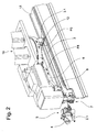
- FIG. 1 and 2 show a cable processing machine 1 with one designed as a belt drive 2 Cable feed device that a cable 3 through a Guide 2.1 a first swivel arm 4 with a first Gripper 5 feeds.
- first drives 6 first swivel arm 4 symbolized by an arrow P1 Rotary motion and / or in an arrow P2 symbolized linear movement. With separating / stripping knives 7 the cable can be disconnected and / or to be stripped.
- the cable processing machine 1 has one second swivel arm 8 with a second gripper 9.
- the second swivel arm 8 into a rotary movement symbolized by an arrow P3 and / or in a symbolized with an arrow P4 Linear movement can be offset.
- the first swivel arm 4 operated as a feed device by means of rotary movement P1 and Linear movement P2 arranged laterally to the longitudinal axis of the cable Processing stations not shown (for example Crimp presses) with leading cable ends.
- the second Swivel arm 8 serves as a feed device by means of Rotary movement P3 and linear movement P4 laterally Cable longitudinal axis arranged, not shown Processing stations (for example crimping presses) with trailing cable ends.
- An example is the effective one by means of the belt drive 2 advanced cable length not 520 mm but only 510 mm.
- the cable feed measured by the belt drive 2 deviates 10 mm downwards.
- the so with the reference measurement The deviation is determined in the following Cable processing to the cable length to be processed related.
- the one with the reference measurement The determined deviation only fits that of the Reference measurement used cables 3. Require other cables renewed reference measurements.
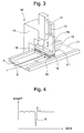
- Fig. 3 shows details of the cable end detector 12 which the Presence of the leading cable end 3.1 on the Cable conveyor belt 11 detected.
- a housing 14 movable carrier 15 with 16 feet moved by means of a cylinder 17 in the direction of arrow P5.
- Piezo elements 18 are between carrier 15 and foot 16 arranged, the pressure of the foot 16 on the leading Cable end 3.1 or on the cable conveyor belt 11 detect.
- the piezo elements 18 generate the piezo elements 18 a signal S according to FIG. 4. If that leading cable end 3.1 leaves the foot 16, the breaks Pressure on the piezo elements 18 briefly and builds up when the foot 16 hits the cable conveyor belt 11 back on.
- the signal S stops the linear movement P2 of the first swivel arm 4.
- the foot 16 has a radius R on, so that laterally offset, leading cable end 3.1 are correctly detected.
- Fig. 5 shows a cable processing machine 1 with only a swivel arm.
- the first swivel arm 4 is not available.
- the cable 3 is as explained above by means of Belt drive 2 to under the separating / stripping knife 7 that cut the cable 3. Then it will Cable 3 advanced further, with the leading cable end 3.1 is transported by means of the conveyor belt 11 and the advanced cable length from the belt drive 2 running is measured. After feeding the belt drive 2 measured target length, the cable end detector 12 presses it Cable 3 on the cable conveyor belt 11 and the belt drive 2 pulls the cable 3 backwards.
- Fig. 6 shows a cable processing machine 1 with as Cable feed device serving pairs of rollers.
- the cable 3 can be advanced by means of a first transport unit 20 and retractable, with upper and lower drivable Roller pairs 20.1 cause the movement of the cable 3.
- the leading cable end 3.1 is in one means Swivel mechanism 21 pivotable, as a feed device serving guide tube 22 to one as a cutting knife 23rd trained processing station advanced, the Cutting knife 23 cuts the leading cable end 3.1.
- Cable 2 is for processing the trailing cable end can be advanced by means of a second transport unit 24 and retractable, with upper and lower drivable pairs of rollers 24.1 cause the movement of the cable 3. During the Measuring the cable length, the roller pairs 24.1 are open.
- the advanced cable length is continuously measured by the transport unit 20. After this Feed of those measured by the transport unit 20
- the cable end detector 12 presses the cable 3 onto the desired length a plate 25 and the transport unit 20 pulls the cable 3 with a backward movement. As soon as the leading Cable end 3.1 leaves the cable end detector 12, the Backward movement of the transport unit 20 by means of a signal of the cable end detector 12 stopped. Correcting the out Cable feed and cable retraction determined deviation is done analogously as explained above.
- the cable end detector 12 can also in the by means of arrow P6 symbolized direction to be movable. In in this case there is no measurement of the cable length Cable retreat.
- the cable end detector 12 is after Lowering in the horizontal direction P6, for example electrically moved until the foot 16 of the cable end detector 12 the leading cable end 3.1 leaves.
- the covered Path of the cable end detector 12 corresponds to that withdrawn Length of the cable 3.
- the correction of the cable feed and determined path of the cable end detector 12 determined Deviation takes place analogously as explained above.
Landscapes
- Engineering & Computer Science (AREA)
- Manufacturing & Machinery (AREA)
- Forwarding And Storing Of Filamentary Material (AREA)
Abstract
im Schritt b) das Kabel (3) um eine vom Bandantrieb (2) gemessene Länge vorgeschoben, wobei das voreilende Kabelende (3.1) unter einem Kabelenddetektor (12) durchbewegt wird und im Schritt c) mittels des ersten Greifers (5) das Kabel (3) festgehalten und mit einer linearen Rückwärtsbewegung (P2) das Kabel zurückgezogen bis das voreilende Kabelende (3.1) den Kabelenddetektor (12) verlässt, wobei aus der vom Bandantrieb (2) gemessenen Kabellänge, aus der Distanz zwischen Trenn-/Abisoliermesser (7) und Kabelenddetektor (12) und aus dem Weg des ersten Greifers (5) während der Rückwärtsbewegung (P2) von einer Steuerung ein Korrekturfaktor berechnet wird.
Description
eine Kabelverarbeitungsmaschine mit zwei Schwenkarmen,
eine Messstrecke mit einem Kabelenddetektor
Einzelheiten des Kabelenddetektors,
ein Signal des Kabelenddetektors,
Ausführungsvarianten der Kabelverarbeitungsmaschine.
Claims (5)
- Einrichtung zur Messung der Länge eines Kabels (3), welches zur Konfektionierung Bearbeitungsstationen zuführbar ist, wobei eine Kabelvorschubeinrichtung (2,20) das Kabel (3) vorschiebt und Zuführeinrichtungen (5,9,22) die Kabelenden den Bearbeitungsstationen zuführen,
dadurch gekennzeichnet, dass zur Durchführung einer Referenzmessung am Ende einer Messstrecke ein Kabelenddetektor (12) vorgesehen ist, der das voreilende Kabelende (3.1) des mittels Kabelvorschubeinrichtung (2,20) vorgeschobenen Kabels (3) detektiert. - Einrichtung nach Anspruch 1,
dadurch gekennzeichnet dass der Kabelenddetektor (12) an einem Träger (15) mit Fuss (16) angeordnete Piezoelemente (18) aufweist, wobei der Fuss (16) auf das Kabel (3) absenkbar ist. - Einrichtung nach einem der Ansprüchen 1 oder 2,
dadurch gekennzeichnet dass der Kabelenddetektor (12) in horizontaler Richtung (P6) bewegbar ist bis mindestens der Fuss (16) des Kabelenddetektors (12) das voreilende Kabelende (3.1) verlässt. - Verfahren zur Messung der Länge eines Kabels (3), welches zur Konfektionierung Bearbeitungsstationen zuführbar ist, wobei eine Kabelvorschubeinrichtung (2,20) das Kabel (3) vorschiebt und Zuführeinrichtungen (5,9,22) die Kabelenden den Bearbeitungsstationen zuführen,
dadurch gekennzeichnet, dass zur Durchführung einer Referenzmessung
im Schritt a) die Kabelvorschubeinrichtung (2,20) das Kabel (3) bis unter Trenn-/Abisoliermesser (7,23) vorschiebt, die das Kabel (3) anschneiden,
im Schritt b) das Kabel (3) um eine von der Kabelvorschubeinrichtung (2,20) gemessene Länge vorgeschoben wird, wobei das voreilende Kabelende (3.1) unter einem Kabelenddetektor (12) durchbewegt wird und
im Schritt c) das Kabel (3) mit einer linearen Rückwärtsbewegung zurückgezogen wird oder der Kabelenddetektor (12) in horizontaler Richtung bewegt wird, bis das voreilende Kabelende (3.1) den Kabelenddetektor (12) verlässt. - Verfahren nach Anspruch 4,
dadurch gekennzeichnet, dass aus der von der Kabelvorschubeinrichtung (2,20) gemessenen Kabellänge, aus der Distanz zwischen Trenn-/Abisoliermesser (7) und Kabelenddetektor (12) (Messstrecke) und aus der Rückwärtsbewegung des Kabels (3) oder der horizontalen Bewegung des Kabelenddetektors (12) von einer Steuerung ein Korrekturfaktor berechnet wird, der bei der der Referenzmessung nachfolgenden Kabelverarbeitung berücksichtigt wird, indem die von der Kabelvorschubeinrichtung (2,20) vorgeschobene Länge korrigiert wird.
Priority Applications (1)
| Application Number | Priority Date | Filing Date | Title |
|---|---|---|---|
| EP03025230.8A EP1424757B1 (de) | 2002-11-26 | 2003-11-05 | Einrichtung zur Messung der Länge eines zu konfektionierenden Kabels |
Applications Claiming Priority (3)
| Application Number | Priority Date | Filing Date | Title |
|---|---|---|---|
| EP02406024 | 2002-11-26 | ||
| EP02406024 | 2002-11-26 | ||
| EP03025230.8A EP1424757B1 (de) | 2002-11-26 | 2003-11-05 | Einrichtung zur Messung der Länge eines zu konfektionierenden Kabels |
Publications (2)
| Publication Number | Publication Date |
|---|---|
| EP1424757A1 true EP1424757A1 (de) | 2004-06-02 |
| EP1424757B1 EP1424757B1 (de) | 2018-03-14 |
Family
ID=32299493
Family Applications (1)
| Application Number | Title | Priority Date | Filing Date |
|---|---|---|---|
| EP03025230.8A Expired - Lifetime EP1424757B1 (de) | 2002-11-26 | 2003-11-05 | Einrichtung zur Messung der Länge eines zu konfektionierenden Kabels |
Country Status (1)
| Country | Link |
|---|---|
| EP (1) | EP1424757B1 (de) |
Cited By (8)
| Publication number | Priority date | Publication date | Assignee | Title |
|---|---|---|---|---|
| EP1993175A2 (de) | 2007-05-12 | 2008-11-19 | Schäfer Werkzeug- und Sondermaschinenbau GmbH | Kabelbearbeitungseinrichtung |
| DE102007040035A1 (de) * | 2007-08-24 | 2009-03-26 | Schäfer Werkzeug- und Sondermaschinenbau GmbH | Verfahren und Vorrichtung zum Erzeugen und nachfolgenden Konfektionieren eines Kabelabschnitts an seinem Vorder- und Hinterende |
| EP2937953A1 (de) * | 2014-04-25 | 2015-10-28 | Komax Holding AG | Verfahren und Vorrichtung zur Herstellung einer Crimpverbindung |
| CN106058614A (zh) * | 2016-06-08 | 2016-10-26 | 国家电网公司 | 高压电缆内应力释放装置及控制方法 |
| CN106736591A (zh) * | 2017-01-24 | 2017-05-31 | 响水县融升空调设备有限公司 | 一种哈芬锚固定槽的自动化生产设备 |
| WO2018077498A1 (de) * | 2016-10-25 | 2018-05-03 | Leoni Bordnetz-Systeme Gmbh | Vorrichtung für die konfektionierung von mantelleitungen |
| WO2019242170A1 (zh) * | 2018-06-22 | 2019-12-26 | 君泰创新(北京)科技有限公司 | 汇流带供给装置 |
| EP3402020B1 (de) * | 2017-05-09 | 2021-07-07 | Schleuniger AG | Kabelbearbeitungsmaschine sowie verfahren zum ablängen eines kabels |
Citations (3)
| Publication number | Priority date | Publication date | Assignee | Title |
|---|---|---|---|---|
| SU1394303A1 (ru) * | 1985-10-03 | 1988-05-07 | Предприятие П/Я А-3667 | Автомат подготовки проводов к монтажу |
| SU1831217A1 (ru) * | 1989-08-02 | 1996-02-20 | Специальное конструкторско-технологическое бюро специального технологического оборудования и технологической оснастки с опытным производством Производственного объединения "Оснастка" | Устройство для мерной резки и зачистки проводов |
| US6135164A (en) * | 1997-09-29 | 2000-10-24 | Komax Holding Ag | Apparatus and method for preparing wires in a harness making machine |
Family Cites Families (1)
| Publication number | Priority date | Publication date | Assignee | Title |
|---|---|---|---|---|
| US5522130A (en) * | 1994-10-13 | 1996-06-04 | Artos Engineering Company | Laser positioning system for wire cutting and stripping apparatus |
-
2003
- 2003-11-05 EP EP03025230.8A patent/EP1424757B1/de not_active Expired - Lifetime
Patent Citations (3)
| Publication number | Priority date | Publication date | Assignee | Title |
|---|---|---|---|---|
| SU1394303A1 (ru) * | 1985-10-03 | 1988-05-07 | Предприятие П/Я А-3667 | Автомат подготовки проводов к монтажу |
| SU1831217A1 (ru) * | 1989-08-02 | 1996-02-20 | Специальное конструкторско-технологическое бюро специального технологического оборудования и технологической оснастки с опытным производством Производственного объединения "Оснастка" | Устройство для мерной резки и зачистки проводов |
| US6135164A (en) * | 1997-09-29 | 2000-10-24 | Komax Holding Ag | Apparatus and method for preparing wires in a harness making machine |
Non-Patent Citations (2)
| Title |
|---|
| DATABASE WPI Section EI Week 198845, Derwent World Patents Index; Class V04, AN 1988-321720, XP002238473 * |
| DATABASE WPI Section EI Week 199641, Derwent World Patents Index; Class V04, AN 1996-411346, XP002238472 * |
Cited By (14)
| Publication number | Priority date | Publication date | Assignee | Title |
|---|---|---|---|---|
| EP1993175A3 (de) * | 2007-05-12 | 2009-11-11 | Schäfer Werkzeug- und Sondermaschinenbau GmbH | Kabelbearbeitungseinrichtung |
| EP1993175A2 (de) | 2007-05-12 | 2008-11-19 | Schäfer Werkzeug- und Sondermaschinenbau GmbH | Kabelbearbeitungseinrichtung |
| DE102007040035A1 (de) * | 2007-08-24 | 2009-03-26 | Schäfer Werkzeug- und Sondermaschinenbau GmbH | Verfahren und Vorrichtung zum Erzeugen und nachfolgenden Konfektionieren eines Kabelabschnitts an seinem Vorder- und Hinterende |
| EP2028732A3 (de) * | 2007-08-24 | 2012-07-25 | Schäfer Werkzeug- und Sondermaschinenbau GmbH | Verfahren und Vorrichtung zum Erzeugen und nachfolgenden Konfektionieren eines Kabelabschnitts an seinem Vorder- und Hinterende |
| US9985404B2 (en) | 2014-04-25 | 2018-05-29 | Koax Holding Ag | Method for producing a cable end crimp connection |
| EP2937953A1 (de) * | 2014-04-25 | 2015-10-28 | Komax Holding AG | Verfahren und Vorrichtung zur Herstellung einer Crimpverbindung |
| JP2015211039A (ja) * | 2014-04-25 | 2015-11-24 | コマツクス・ホールデイング・アー・ゲー | 圧着接続部を製造するための方法および装置 |
| CN106058614A (zh) * | 2016-06-08 | 2016-10-26 | 国家电网公司 | 高压电缆内应力释放装置及控制方法 |
| CN106058614B (zh) * | 2016-06-08 | 2018-02-23 | 国家电网公司 | 高压电缆内应力释放装置及控制方法 |
| WO2018077498A1 (de) * | 2016-10-25 | 2018-05-03 | Leoni Bordnetz-Systeme Gmbh | Vorrichtung für die konfektionierung von mantelleitungen |
| CN106736591A (zh) * | 2017-01-24 | 2017-05-31 | 响水县融升空调设备有限公司 | 一种哈芬锚固定槽的自动化生产设备 |
| CN106736591B (zh) * | 2017-01-24 | 2019-07-26 | 响水县融升科技有限公司 | 一种哈芬锚固定槽的自动化生产设备 |
| EP3402020B1 (de) * | 2017-05-09 | 2021-07-07 | Schleuniger AG | Kabelbearbeitungsmaschine sowie verfahren zum ablängen eines kabels |
| WO2019242170A1 (zh) * | 2018-06-22 | 2019-12-26 | 君泰创新(北京)科技有限公司 | 汇流带供给装置 |
Also Published As
| Publication number | Publication date |
|---|---|
| EP1424757B1 (de) | 2018-03-14 |
Similar Documents
| Publication | Publication Date | Title |
|---|---|---|
| EP0423443B1 (de) | Verfahren und Einrichtung zur Durchführung des Verfahrens zum Zubringen eines Kabels in einen Kabel-Verarbeitungsautomaten | |
| DE69508530T2 (de) | Verfahren und Vorrichtung zum Halten einer Stretchfolie und Verwenden zum Umhüllen | |
| EP2273567A1 (de) | Verfahren und Vorrichtung zum Recken von Lötband | |
| EP0889561A1 (de) | Krimpvorrichtung und Verfahren zu deren Betrieb | |
| US6886438B2 (en) | Device for measuring the length of a cable for processing | |
| DE69301559T2 (de) | Greifvorrichtung für Reifenlaufflächen | |
| DE2640496A1 (de) | Beschickungsvorrichtung fuer einen anleger | |
| EP1424757B1 (de) | Einrichtung zur Messung der Länge eines zu konfektionierenden Kabels | |
| EP1079478A1 (de) | Verfahren zum Abtrennen und/oder Entfernen der Isolierung von Kabeln, sowie eine Vorrichtung zur Durchführung dieses Verfahrens | |
| DE4110342A1 (de) | Verfahren zum ersetzen von streifenmaterial an einer fertigungsmaschine | |
| DE69520760T2 (de) | Vorrichtung und Verfahren zur Messung von Crimphöhe | |
| DE60107237T2 (de) | Zuführeinrichtung zum zuführen von gummimaterial zu einer schneideinrichtung | |
| DE69300736T2 (de) | Vorrichtung zum Anpressen von Kabelendklemmen. | |
| WO2022017970A1 (de) | Verfahren und vorrichtung zum anbringen von wicklungen | |
| EP0708050B1 (de) | Kabeltransport- und Schwenkvorrichtung | |
| EP1811851B1 (de) | Verfahren und vorrichtung zum schneiden von würsten | |
| DE60101962T2 (de) | Spleissvorrichtung zum spleissen von gummibeschichteten kordbandstreifen | |
| EP0515581B1 (de) | Vorrichtung zum herstellen von wickeln aus federstahlgewirk | |
| DE102006033987A1 (de) | Zubringereinrichtung | |
| DE8705796U1 (de) | Vorrichtung zum Herstellen von Abstandhalterrahmen für Isolierglasscheiben | |
| DE102014011689A1 (de) | Vorrichtung und Verfahren zur Durchführung von Kappschnitten an Werkstücken aus Holz | |
| DE3900776C2 (de) | Vorrichtung zum Ausrichten der seitlichen Position eines blattförmigen Elements | |
| EP1403983B1 (de) | Kabelbearbeitungsmaschine mit einer Schwenkeinrichtung zum Bedienen von Bearbeitungsstationen mit Kabelenden | |
| DE10044815C2 (de) | Einrichtung zur Förderung blattartiger Gegenstände | |
| CH693370A5 (de) | Verfahren und Vorichtung zur Ueberführung von Kontakten zu einer Kontaktverarbeitungsstation. |
Legal Events
| Date | Code | Title | Description |
|---|---|---|---|
| PUAI | Public reference made under article 153(3) epc to a published international application that has entered the european phase |
Free format text: ORIGINAL CODE: 0009012 |
|
| AK | Designated contracting states |
Kind code of ref document: A1 Designated state(s): AT BE BG CH CY CZ DE DK EE ES FI FR GB GR HU IE IT LI LU MC NL PT RO SE SI SK TR |
|
| AX | Request for extension of the european patent |
Extension state: AL LT LV MK |
|
| 17P | Request for examination filed |
Effective date: 20041112 |
|
| AKX | Designation fees paid |
Designated state(s): CH DE FR GB IT LI |
|
| 17Q | First examination report despatched |
Effective date: 20170222 |
|
| GRAP | Despatch of communication of intention to grant a patent |
Free format text: ORIGINAL CODE: EPIDOSNIGR1 |
|
| INTG | Intention to grant announced |
Effective date: 20171123 |
|
| GRAS | Grant fee paid |
Free format text: ORIGINAL CODE: EPIDOSNIGR3 |
|
| GRAA | (expected) grant |
Free format text: ORIGINAL CODE: 0009210 |
|
| AK | Designated contracting states |
Kind code of ref document: B1 Designated state(s): CH DE FR GB IT LI |
|
| REG | Reference to a national code |
Ref country code: GB Ref legal event code: FG4D Free format text: NOT ENGLISH |
|
| REG | Reference to a national code |
Ref country code: CH Ref legal event code: EP |
|
| REG | Reference to a national code |
Ref country code: DE Ref legal event code: R096 Ref document number: 50315739 Country of ref document: DE |
|
| REG | Reference to a national code |
Ref country code: CH Ref legal event code: NV Representative=s name: INVENTIO AG, CH |
|
| REG | Reference to a national code |
Ref country code: DE Ref legal event code: R097 Ref document number: 50315739 Country of ref document: DE |
|
| PLBE | No opposition filed within time limit |
Free format text: ORIGINAL CODE: 0009261 |
|
| STAA | Information on the status of an ep patent application or granted ep patent |
Free format text: STATUS: NO OPPOSITION FILED WITHIN TIME LIMIT |
|
| 26N | No opposition filed |
Effective date: 20181217 |
|
| PGFP | Annual fee paid to national office [announced via postgrant information from national office to epo] |
Ref country code: IT Payment date: 20181126 Year of fee payment: 16 |
|
| GBPC | Gb: european patent ceased through non-payment of renewal fee |
Effective date: 20181105 |
|
| PG25 | Lapsed in a contracting state [announced via postgrant information from national office to epo] |
Ref country code: GB Free format text: LAPSE BECAUSE OF NON-PAYMENT OF DUE FEES Effective date: 20181105 |
|
| PGFP | Annual fee paid to national office [announced via postgrant information from national office to epo] |
Ref country code: DE Payment date: 20191121 Year of fee payment: 17 |
|
| PG25 | Lapsed in a contracting state [announced via postgrant information from national office to epo] |
Ref country code: FR Free format text: LAPSE BECAUSE OF NON-PAYMENT OF DUE FEES Effective date: 20191130 Ref country code: IT Free format text: LAPSE BECAUSE OF NON-PAYMENT OF DUE FEES Effective date: 20191105 |
|
| REG | Reference to a national code |
Ref country code: DE Ref legal event code: R119 Ref document number: 50315739 Country of ref document: DE |
|
| PG25 | Lapsed in a contracting state [announced via postgrant information from national office to epo] |
Ref country code: DE Free format text: LAPSE BECAUSE OF NON-PAYMENT OF DUE FEES Effective date: 20210601 |
|
| PGFP | Annual fee paid to national office [announced via postgrant information from national office to epo] |
Ref country code: CH Payment date: 20221123 Year of fee payment: 20 |
|
| REG | Reference to a national code |
Ref country code: CH Ref legal event code: PL |