EP1422449A2 - Kupplungsbremsung eines Mehrgangsgetriebes - Google Patents
Kupplungsbremsung eines Mehrgangsgetriebes Download PDFInfo
- Publication number
- EP1422449A2 EP1422449A2 EP03257272A EP03257272A EP1422449A2 EP 1422449 A2 EP1422449 A2 EP 1422449A2 EP 03257272 A EP03257272 A EP 03257272A EP 03257272 A EP03257272 A EP 03257272A EP 1422449 A2 EP1422449 A2 EP 1422449A2
- Authority
- EP
- European Patent Office
- Prior art keywords
- clutches
- stage
- clutch
- range
- transmission system
- Prior art date
- Legal status (The legal status is an assumption and is not a legal conclusion. Google has not performed a legal analysis and makes no representation as to the accuracy of the status listed.)
- Granted
Links
Images
Classifications
-
- F—MECHANICAL ENGINEERING; LIGHTING; HEATING; WEAPONS; BLASTING
- F16—ENGINEERING ELEMENTS AND UNITS; GENERAL MEASURES FOR PRODUCING AND MAINTAINING EFFECTIVE FUNCTIONING OF MACHINES OR INSTALLATIONS; THERMAL INSULATION IN GENERAL
- F16H—GEARING
- F16H61/00—Control functions within control units of change-speed- or reversing-gearings for conveying rotary motion ; Control of exclusively fluid gearing, friction gearing, gearings with endless flexible members or other particular types of gearing
-
- F—MECHANICAL ENGINEERING; LIGHTING; HEATING; WEAPONS; BLASTING
- F16—ENGINEERING ELEMENTS AND UNITS; GENERAL MEASURES FOR PRODUCING AND MAINTAINING EFFECTIVE FUNCTIONING OF MACHINES OR INSTALLATIONS; THERMAL INSULATION IN GENERAL
- F16H—GEARING
- F16H59/00—Control inputs to control units of change-speed- or reversing-gearings for conveying rotary motion
- F16H59/68—Inputs being a function of gearing status
- F16H59/72—Inputs being a function of gearing status dependent on oil characteristics, e.g. temperature, viscosity
- F16H2059/725—Sensing or calculating temperature of oil in friction devices, e.g. wet clutches, to prevent overheating of friction linings
-
- F—MECHANICAL ENGINEERING; LIGHTING; HEATING; WEAPONS; BLASTING
- F16—ENGINEERING ELEMENTS AND UNITS; GENERAL MEASURES FOR PRODUCING AND MAINTAINING EFFECTIVE FUNCTIONING OF MACHINES OR INSTALLATIONS; THERMAL INSULATION IN GENERAL
- F16H—GEARING
- F16H59/00—Control inputs to control units of change-speed- or reversing-gearings for conveying rotary motion
- F16H59/68—Inputs being a function of gearing status
- F16H59/72—Inputs being a function of gearing status dependent on oil characteristics, e.g. temperature, viscosity
-
- F—MECHANICAL ENGINEERING; LIGHTING; HEATING; WEAPONS; BLASTING
- F16—ENGINEERING ELEMENTS AND UNITS; GENERAL MEASURES FOR PRODUCING AND MAINTAINING EFFECTIVE FUNCTIONING OF MACHINES OR INSTALLATIONS; THERMAL INSULATION IN GENERAL
- F16H—GEARING
- F16H61/00—Control functions within control units of change-speed- or reversing-gearings for conveying rotary motion ; Control of exclusively fluid gearing, friction gearing, gearings with endless flexible members or other particular types of gearing
- F16H61/0059—Braking of gear output shaft using simultaneous engagement of engaging means, e.g. clutches or brakes, applied for different gear ratios
Definitions
- the present invention relates to an apparatus for clutch braking in a multi-speed transmission of a vehicle.
- the present invention is directed toward an apparatus for clutch braking in a multi-speed transmission.
- the invention comprises a prime mover, a transmission system, an output shaft and a torque converter.
- the transmission system comprises a first and a second stage.
- the first stage comprises at least two range clutches and the second stage comprises at least two direction clutches.
- transmission system braking is achieved by locking one of the range clutches and one of the direction clutches. Also, at least one other range clutch and at least one other direction clutch are slipped.
- At least two range clutches are locked together and all of the direction clutches are slipped about the locked range clutches to brake the transmission system.
- the range clutches of the transmission are opened, one of the direction clutches is locked and the remaining direction clutch is slipped to brake the transmission system.
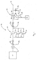
- a first preferred embodiment of the present invention is schematically depicted comprising a prime mover 10, a transmission system 12, an output shaft 14 and a torque converter 16 of a vehicle (not shown).
- the prime mover 10 is preferably an internal combustion engine as known to those skilled in the art.
- the transmission system 12 comprises a first stage 18 and a second stage 20.
- the present invention also applies to transmission systems comprising more than two stages.
- the first stage 18 comprises at least two range clutches 21.
- the range clutches 21 may be such as a first gear clutch 22, a second gear clutch 24, or any number of additional gear clutches N, as known to those skilled in the art. Although only three gear clutches are described and depicted, it is well within the scope of the present invention to have more or fewer gear clutches.
- the second stage 20 comprises at least two direction clutches 25.
- the direction clutches 25 may be such as a forward direction clutch 26 and a reverse direction clutch 28, although those skilled in the art know that direction clutches 25 can also comprise at least forward high and forward low and reverse high and reverse low.
- the present invention is described as having the first stage 18 adjacent the torque converter 16 and the second stage 20 adjacent the output shaft 14, it is well within the scope of the present invention to switch the position of the first stage 18 and the second stage 20.
- direction clutches 25 are designed with a higher heat absorbing capacity and a higher heat removing capacity as compared to the range clutches 21.
- the higher heat absorbing and removing capacity of the direction clutches 25 is due to the greater mass of the clutches 25 and the additional cooling fluid flow provided to each of the clutches 25.
- the present invention also may include at least one selectively operated pump 30 in fluid communication with at least each of the direction clutches 25 of the transmission system 12 to provide lubricating fluid to the clutches 25.
- the pump 30 circulates cooling fluid, in addition to the fluid with the transmission system 12, through the clutches 25 thereby increasing their capacity to absorb and remove heat from the clutches 25.
- the pump 30 may be selectively automatically or manually engaged to provide fluid to one or more braking clutches 25.
- the torque converter 16 is well known to those skilled in the art and connects the prime mover 10 to the transmission system 12 through a turbine shaft 32.
- Other components of the invention comprise an intermediate shaft 34 connecting the first stage 18 with the second stage 20.
- the output shaft 14 connects the second stage 20 with the remaining drivetrain (not shown) of the vehicle.
- a reverse idler gear 36 may also be connected to the reverse clutch 28 to the output shaft 14 as known to those skilled in the art.
- At least one gear ratio R1 is located between the turbine shaft 32 and a range gear 21.
- at least one gear ratio R2 is located between a range gear 21 and the intermediate shaft 34.
- At least one of the range clutches 21 and one of the directional clutches 25 are kinematically locked to one another.
- at least one of the other range clutches 21 is slipped with the locked range clutch 21 and at least one other directional clutch 25 is slipped with the locked directional clutch 25.
- the slipping range clutch 21 and direction clutch 25 effectively brake the transmission system 12 by slowing the locked range 21 and direction clutch 25, respectively.
- the direction clutches 25 comprise at least one forward clutch 38 and at least one reverse clutch 42.
- the forward clutch 38 is kinematically locked with the first gear clutch 22 and the at least one other gear clutch, such as N or 24, is slipped with the locked first gear clutch 22 and the reverse clutch 42 is slipped with the locked forward clutch 38. If there are any other clutches in the second stage, such as a forward high gear and/or a forward low gear, they may also be slipped to provide braking.
- Additional braking to the transmission system 12 is provided if the engine 10 is de-throttled to a relatively low revolutions per minute setting.
- the low setting allows the turbine shaft 32 to communicate rotational energy from the locked range clutch 22 to the torque converter 16 where the rotational energy is absorbed.
- a second embodiment differs from the first embodiment since the engine 10 has been de-throttled to reduce the revolutions per minute.
- the kinematic link which existed between the first 18 and second 20 stages is opened.
- At least two of the range clutches 21 are then locked together so that the relative motion between them is zero. Any combination of range clutches 21 can be locked, so it need not be just first gear clutch 22 and second gear clutch 24.
- the directional clutches 25 are slipped about the locked range clutches 21 to brake the transmission system 12.
- the direction clutches 25 comprise at least one forward clutch 38 and at least one reverse clutch 42, although other direction clutches known to those skilled in the art may be used.
- the forward clutch 38 and the reverse clutch 42 are slipped about the at least two locked range clutches 21 to brake the transmission system 12.
- the heaviest clutches of the transmission system 12 can be used to absorb and/or remove heat for braking the system.
- a third embodiment differs from the above-described embodiments since the kinematic link between the first stage 18 and the second stage 20 is broken and the range clutches 21 are opened.
- the engine 10 can perform independently in this embodiment since the torque converter 16 is also opened.
- the engine 10 can increase in revolutions per minute to supply power to auxiliary hydraulics and/or to supply cooling fluid to the transmission system 12.
- one of the smaller direction clutches 25 is locked and any other direction clutches 25 slip.
- the reverse clutch 42 is locked and the and the forward clutch 38 is slipped.
- the direction clutches 25 include a forward high or a forward low and/or a reverse high or a reverse low, it is preferred that one of those clutches become locked as they will likely be the smallest direction clutches 25.
- Those skilled in the art appreciate that it is preferred to lock the smallest direction clutch 25 as it cannot remove and/or absorb as much heat as a larger directional clutch 25. The remaining unlocked directional clutches 25 can the be slipped to slow the transmission system 12.
- the above-described multi-speed transmission can brake the vehicle by downshifting from a higher range gear to a lower range gear.
- Downshifting is a well-known technique wherein the engine 10 is de-throttled to reduce engine revolutions per minute. Moving from a higher range gear to a lower range gear and engaging the lower range gear causes the turbine side of the torque converter 16 to rotate at a higher speed than when the turbine side was driven by the lower range gear. With the lower range gear engaged, the turbine rotates at a higher rate than the side of the torque converter 16 connected to the engine 10. The rotational energy of the turbine side is in effect braked by the slower moving engine side thus slowing the entire transmission system 12.
Landscapes
- Engineering & Computer Science (AREA)
- General Engineering & Computer Science (AREA)
- Mechanical Engineering (AREA)
- Structure Of Transmissions (AREA)
Applications Claiming Priority (4)
| Application Number | Priority Date | Filing Date | Title |
|---|---|---|---|
| US42781202P | 2002-11-20 | 2002-11-20 | |
| US427812P | 2002-11-20 | ||
| US677928 | 2003-10-02 | ||
| US10/677,928 US6872164B2 (en) | 2002-11-20 | 2003-10-02 | Clutch braking in a multi-speed transmission |
Publications (3)
| Publication Number | Publication Date |
|---|---|
| EP1422449A2 true EP1422449A2 (de) | 2004-05-26 |
| EP1422449A3 EP1422449A3 (de) | 2007-08-08 |
| EP1422449B1 EP1422449B1 (de) | 2010-09-08 |
Family
ID=32233678
Family Applications (1)
| Application Number | Title | Priority Date | Filing Date |
|---|---|---|---|
| EP03257272A Expired - Lifetime EP1422449B1 (de) | 2002-11-20 | 2003-11-18 | Kupplungsbremsung eines Mehrgangsgetriebes |
Country Status (4)
| Country | Link |
|---|---|
| US (1) | US6872164B2 (de) |
| EP (1) | EP1422449B1 (de) |
| AT (1) | ATE480726T1 (de) |
| DE (1) | DE60334060D1 (de) |
Cited By (4)
| Publication number | Priority date | Publication date | Assignee | Title |
|---|---|---|---|---|
| WO2010122428A1 (en) * | 2009-04-20 | 2010-10-28 | Spicer Off-Highway Belgium N.V. | Hybrid transmission and method of use |
| EP1908996A3 (de) * | 2006-10-03 | 2011-06-08 | J.C. Bamford Excavators Ltd. | Verfahren zur Steuerung eines Fahrzeuggetriebes |
| WO2013184751A1 (en) * | 2012-06-07 | 2013-12-12 | Cnh America Llc | System and method for performing shuttle shifts with a transmission of a work vehicle |
| WO2017153328A1 (en) * | 2016-03-06 | 2017-09-14 | Dana Belgium N.V. | Driveline for a vehicle including an electric drive motor and a powershift transmission having at least two transmission stages |
Families Citing this family (22)
| Publication number | Priority date | Publication date | Assignee | Title |
|---|---|---|---|---|
| WO2011094223A1 (en) * | 2010-01-26 | 2011-08-04 | Martin Burgbacher | Gear assembly for motor vehicle |
| US10670124B2 (en) | 2013-12-31 | 2020-06-02 | Deere & Company | Multi-mode infinitely variable transmission |
| US10655710B2 (en) | 2013-12-31 | 2020-05-19 | Deere & Company | Multi-mode infinitely variable transmission that provides seamless shifting |
| US10647193B2 (en) | 2014-04-09 | 2020-05-12 | Deere & Company | Multi-mode power trains |
| US10738868B2 (en) | 2014-04-09 | 2020-08-11 | Deere & Company | Multi-mode powertrains |
| US10619711B2 (en) | 2017-04-12 | 2020-04-14 | Deere & Company | Infinitely variable transmission with power reverser |
| US11052747B2 (en) | 2018-05-04 | 2021-07-06 | Deere & Company | Multi-mode powertrains |
| US11091018B2 (en) | 2018-05-11 | 2021-08-17 | Deere & Company | Powertrain with variable vertical drop distance |
| US10975959B2 (en) | 2019-04-01 | 2021-04-13 | Deere & Company | Transmission clutch braking control system |
| US11137052B2 (en) | 2019-08-29 | 2021-10-05 | Deere & Company | Transmission assembly with integrated CVP |
| US11351983B2 (en) | 2019-10-31 | 2022-06-07 | Deere & Company | Power control system with transmission transient boost function |
| US11846085B2 (en) | 2020-02-17 | 2023-12-19 | Deere & Company | Energy management system for a hybrid vehicle with an electrically powered hydraulic system |
| US11370406B2 (en) | 2020-03-05 | 2022-06-28 | Deere & Company | Power control system with clutch braking function |
| US11325459B2 (en) | 2020-10-09 | 2022-05-10 | Deere & Company | Low profile transmission assembly with integrated CVP |
| US11654900B2 (en) | 2020-12-08 | 2023-05-23 | Deere & Company | Vehicle stop transmission control system and method |
| US11613246B2 (en) | 2021-01-21 | 2023-03-28 | Deere & Company | Power control system with engine throttle shift function |
| US11628822B2 (en) | 2021-02-09 | 2023-04-18 | Deere & Company | Power control system with stall prevention clutch modulation function |
| US11299141B1 (en) | 2021-02-10 | 2022-04-12 | Deere & Company | System for multi-layer braking and retardation in a work vehicle |
| US11820361B2 (en) | 2021-11-30 | 2023-11-21 | Deere & Company | Transmission assembly with electrical machine unit for improved shift quality |
| US11607948B1 (en) | 2021-12-22 | 2023-03-21 | Deere & Company | Electronically-variable power shift transmission for work vehicles |
| US11585412B1 (en) | 2021-12-22 | 2023-02-21 | Deere & Company | Electronically-variable, dual-path power shift transmission for work vehicles |
| US11913528B1 (en) | 2022-10-28 | 2024-02-27 | Deere & Company | Multi-mode continuously variable transmission assembly with drop set arrangement |
Family Cites Families (11)
| Publication number | Priority date | Publication date | Assignee | Title |
|---|---|---|---|---|
| US3651904A (en) * | 1970-06-16 | 1972-03-28 | Twin Disc Inc | Transmission with simultaneously engaged clutches for braking |
| US4090414A (en) * | 1976-04-14 | 1978-05-23 | Twin Disc, Incorporated | Transmission control system for shuttle type vehicles |
| DE3000968A1 (de) * | 1980-01-12 | 1981-07-23 | Voith Getriebe Kg | Hydrodynamisches wendegetriebe |
| US4843902A (en) * | 1986-08-07 | 1989-07-04 | Cooper Industries, Inc. | Control system for powershift transmission clutches |
| FR2662483A2 (fr) * | 1990-02-28 | 1991-11-29 | Antonov Roumen | Dispositif de transmission a rapport variable en particulier pour l'automobile. |
| US5353662A (en) * | 1993-01-29 | 1994-10-11 | Deere & Company | Transmission shuttle shift deceleration method |
| JP2923839B2 (ja) * | 1994-09-20 | 1999-07-26 | 本田技研工業株式会社 | 油圧制御装置 |
| DE19612863A1 (de) * | 1996-03-30 | 1997-10-02 | Zahnradfabrik Friedrichshafen | Getriebesteuerung zur Reduzierung der thermischen Belastung von Schaltelementen eines Wendegetriebes |
| DE19734825C1 (de) * | 1997-08-12 | 1999-12-16 | Clark Equipment Belgium Nv | Lastschaltgetriebe für eine fahrbare Arbeitsmaschine |
| US6371885B1 (en) * | 1999-04-01 | 2002-04-16 | Komatsu Ltd. | Working vehicle and vehicle speed control method thereof, variable power engine and power setting method thereof, and vehicle with variable power engine and power control method thereof |
| JP2001116070A (ja) * | 1999-10-18 | 2001-04-27 | Toyota Autom Loom Works Ltd | 産業車両の制動制御装置 |
-
2003
- 2003-10-02 US US10/677,928 patent/US6872164B2/en not_active Expired - Lifetime
- 2003-11-18 EP EP03257272A patent/EP1422449B1/de not_active Expired - Lifetime
- 2003-11-18 DE DE60334060T patent/DE60334060D1/de not_active Expired - Lifetime
- 2003-11-18 AT AT03257272T patent/ATE480726T1/de not_active IP Right Cessation
Cited By (7)
| Publication number | Priority date | Publication date | Assignee | Title |
|---|---|---|---|---|
| EP1908996A3 (de) * | 2006-10-03 | 2011-06-08 | J.C. Bamford Excavators Ltd. | Verfahren zur Steuerung eines Fahrzeuggetriebes |
| WO2010122428A1 (en) * | 2009-04-20 | 2010-10-28 | Spicer Off-Highway Belgium N.V. | Hybrid transmission and method of use |
| US8353804B2 (en) | 2009-04-20 | 2013-01-15 | Spicer Off-Highway Belguim N.V. | Hybrid transmission and method of use |
| WO2013184751A1 (en) * | 2012-06-07 | 2013-12-12 | Cnh America Llc | System and method for performing shuttle shifts with a transmission of a work vehicle |
| WO2017153328A1 (en) * | 2016-03-06 | 2017-09-14 | Dana Belgium N.V. | Driveline for a vehicle including an electric drive motor and a powershift transmission having at least two transmission stages |
| US10851879B2 (en) | 2016-03-06 | 2020-12-01 | Dana Belgium N.V. | Driveline for a vehicle including an electric drive motor and a powershift transmission having at least two transmission stages |
| US11236809B2 (en) | 2016-03-06 | 2022-02-01 | Dana Belgium N.V. | Driveline for a vehicle including an electric drive motor and a powershift transmission having at least two transmission stages |
Also Published As
| Publication number | Publication date |
|---|---|
| EP1422449A3 (de) | 2007-08-08 |
| DE60334060D1 (de) | 2010-10-21 |
| US20040094381A1 (en) | 2004-05-20 |
| ATE480726T1 (de) | 2010-09-15 |
| US6872164B2 (en) | 2005-03-29 |
| EP1422449B1 (de) | 2010-09-08 |
Similar Documents
| Publication | Publication Date | Title |
|---|---|---|
| US6872164B2 (en) | Clutch braking in a multi-speed transmission | |
| US6761658B1 (en) | Four mode hydro-mechanical transmission | |
| US7841960B2 (en) | Eight speed planetary kinematic arrangement with two rotating clutches | |
| CA2552900A1 (en) | Hybrid powertrain system including smooth shifting automated transmission | |
| US5667451A (en) | Power train of automatic transmission for vehicle | |
| US6159123A (en) | Gearbox with retarder | |
| CN1612985A (zh) | 液力机械连续可变传动装置 | |
| JP2728861B2 (ja) | 車両用自動変速機のパワートレーン | |
| WO2013130376A1 (en) | Multi-speed automatic transmission with fast reverse | |
| CN1558125A (zh) | 离偶合器式自动变速器 | |
| CN103591166B (zh) | 离合器及车辆变速总成 | |
| US5823909A (en) | Multiple speed automatic transaxle for a motor vehicle | |
| JP2728644B2 (ja) | 車両用自動変速機のパワートレーン | |
| JPS596459A (ja) | 連続的に可変の伝動装置 | |
| CN107975578B (zh) | 原始移位系统 | |
| US10267385B2 (en) | Multi-speed transmission | |
| US20070265132A1 (en) | Transmission Device For an Auxiliary or Accessory of a Variable-Speed Engine, an Engine Equipped Therewith and Uses Thereof | |
| KR100418662B1 (ko) | 자동변속차량의엔진과열방지방법 | |
| CN111055670B (zh) | 一种多档位汽车混合动力驱动装置及汽车 | |
| JPH068738A (ja) | センターディファレンシャル装置付駆動装置 | |
| KR100244941B1 (ko) | 4속 자동 변속기 | |
| KR920009578B1 (ko) | 차량용 자동 변속기의 1축 5속 변속기구 | |
| JPH05201264A (ja) | センターディファレンシャル装置付4輪駆動車 | |
| KR0131316B1 (ko) | 자동차의 자동 변속장치 | |
| KR100244753B1 (ko) | 4속 자동 변속기 |
Legal Events
| Date | Code | Title | Description |
|---|---|---|---|
| PUAI | Public reference made under article 153(3) epc to a published international application that has entered the european phase |
Free format text: ORIGINAL CODE: 0009012 |
|
| AK | Designated contracting states |
Kind code of ref document: A2 Designated state(s): AT BE BG CH CY CZ DE DK EE ES FI FR GB GR HU IE IT LI LU MC NL PT RO SE SI SK TR |
|
| AX | Request for extension of the european patent |
Extension state: AL LT LV MK |
|
| PUAL | Search report despatched |
Free format text: ORIGINAL CODE: 0009013 |
|
| AK | Designated contracting states |
Kind code of ref document: A3 Designated state(s): AT BE BG CH CY CZ DE DK EE ES FI FR GB GR HU IE IT LI LU MC NL PT RO SE SI SK TR |
|
| AX | Request for extension of the european patent |
Extension state: AL LT LV MK |
|
| RIC1 | Information provided on ipc code assigned before grant |
Ipc: F16H 61/00 20060101AFI20070629BHEP |
|
| 17P | Request for examination filed |
Effective date: 20080204 |
|
| AKX | Designation fees paid |
Designated state(s): AT BE BG CH CY CZ DE DK EE ES FI FR GB GR HU IE IT LI LU MC NL PT RO SE SI SK TR |
|
| 17Q | First examination report despatched |
Effective date: 20090616 |
|
| GRAP | Despatch of communication of intention to grant a patent |
Free format text: ORIGINAL CODE: EPIDOSNIGR1 |
|
| GRAJ | Information related to disapproval of communication of intention to grant by the applicant or resumption of examination proceedings by the epo deleted |
Free format text: ORIGINAL CODE: EPIDOSDIGR1 |
|
| GRAP | Despatch of communication of intention to grant a patent |
Free format text: ORIGINAL CODE: EPIDOSNIGR1 |
|
| GRAS | Grant fee paid |
Free format text: ORIGINAL CODE: EPIDOSNIGR3 |
|
| GRAA | (expected) grant |
Free format text: ORIGINAL CODE: 0009210 |
|
| AK | Designated contracting states |
Kind code of ref document: B1 Designated state(s): AT BE BG CH CY CZ DE DK EE ES FI FR GB GR HU IE IT LI LU MC NL PT RO SE SI SK TR |
|
| REG | Reference to a national code |
Ref country code: GB Ref legal event code: FG4D |
|
| REG | Reference to a national code |
Ref country code: CH Ref legal event code: EP |
|
| REG | Reference to a national code |
Ref country code: IE Ref legal event code: FG4D |
|
| REF | Corresponds to: |
Ref document number: 60334060 Country of ref document: DE Date of ref document: 20101021 Kind code of ref document: P |
|
| REG | Reference to a national code |
Ref country code: SE Ref legal event code: TRGR |
|
| REG | Reference to a national code |
Ref country code: NL Ref legal event code: VDEP Effective date: 20100908 |
|
| PG25 | Lapsed in a contracting state [announced via postgrant information from national office to epo] |
Ref country code: AT Free format text: LAPSE BECAUSE OF FAILURE TO SUBMIT A TRANSLATION OF THE DESCRIPTION OR TO PAY THE FEE WITHIN THE PRESCRIBED TIME-LIMIT Effective date: 20100908 Ref country code: FI Free format text: LAPSE BECAUSE OF FAILURE TO SUBMIT A TRANSLATION OF THE DESCRIPTION OR TO PAY THE FEE WITHIN THE PRESCRIBED TIME-LIMIT Effective date: 20100908 |
|
| PG25 | Lapsed in a contracting state [announced via postgrant information from national office to epo] |
Ref country code: CY Free format text: LAPSE BECAUSE OF FAILURE TO SUBMIT A TRANSLATION OF THE DESCRIPTION OR TO PAY THE FEE WITHIN THE PRESCRIBED TIME-LIMIT Effective date: 20100908 Ref country code: SI Free format text: LAPSE BECAUSE OF FAILURE TO SUBMIT A TRANSLATION OF THE DESCRIPTION OR TO PAY THE FEE WITHIN THE PRESCRIBED TIME-LIMIT Effective date: 20100908 |
|
| PG25 | Lapsed in a contracting state [announced via postgrant information from national office to epo] |
Ref country code: GR Free format text: LAPSE BECAUSE OF FAILURE TO SUBMIT A TRANSLATION OF THE DESCRIPTION OR TO PAY THE FEE WITHIN THE PRESCRIBED TIME-LIMIT Effective date: 20101209 Ref country code: NL Free format text: LAPSE BECAUSE OF FAILURE TO SUBMIT A TRANSLATION OF THE DESCRIPTION OR TO PAY THE FEE WITHIN THE PRESCRIBED TIME-LIMIT Effective date: 20100908 |
|
| PG25 | Lapsed in a contracting state [announced via postgrant information from national office to epo] |
Ref country code: EE Free format text: LAPSE BECAUSE OF FAILURE TO SUBMIT A TRANSLATION OF THE DESCRIPTION OR TO PAY THE FEE WITHIN THE PRESCRIBED TIME-LIMIT Effective date: 20100908 Ref country code: SK Free format text: LAPSE BECAUSE OF FAILURE TO SUBMIT A TRANSLATION OF THE DESCRIPTION OR TO PAY THE FEE WITHIN THE PRESCRIBED TIME-LIMIT Effective date: 20100908 Ref country code: PT Free format text: LAPSE BECAUSE OF FAILURE TO SUBMIT A TRANSLATION OF THE DESCRIPTION OR TO PAY THE FEE WITHIN THE PRESCRIBED TIME-LIMIT Effective date: 20110110 Ref country code: RO Free format text: LAPSE BECAUSE OF FAILURE TO SUBMIT A TRANSLATION OF THE DESCRIPTION OR TO PAY THE FEE WITHIN THE PRESCRIBED TIME-LIMIT Effective date: 20100908 Ref country code: CZ Free format text: LAPSE BECAUSE OF FAILURE TO SUBMIT A TRANSLATION OF THE DESCRIPTION OR TO PAY THE FEE WITHIN THE PRESCRIBED TIME-LIMIT Effective date: 20100908 |
|
| PG25 | Lapsed in a contracting state [announced via postgrant information from national office to epo] |
Ref country code: BE Free format text: LAPSE BECAUSE OF FAILURE TO SUBMIT A TRANSLATION OF THE DESCRIPTION OR TO PAY THE FEE WITHIN THE PRESCRIBED TIME-LIMIT Effective date: 20100908 Ref country code: ES Free format text: LAPSE BECAUSE OF FAILURE TO SUBMIT A TRANSLATION OF THE DESCRIPTION OR TO PAY THE FEE WITHIN THE PRESCRIBED TIME-LIMIT Effective date: 20101219 Ref country code: MC Free format text: LAPSE BECAUSE OF NON-PAYMENT OF DUE FEES Effective date: 20101130 |
|
| REG | Reference to a national code |
Ref country code: CH Ref legal event code: PL |
|
| PLBE | No opposition filed within time limit |
Free format text: ORIGINAL CODE: 0009261 |
|
| STAA | Information on the status of an ep patent application or granted ep patent |
Free format text: STATUS: NO OPPOSITION FILED WITHIN TIME LIMIT |
|
| PG25 | Lapsed in a contracting state [announced via postgrant information from national office to epo] |
Ref country code: LI Free format text: LAPSE BECAUSE OF NON-PAYMENT OF DUE FEES Effective date: 20101130 Ref country code: CH Free format text: LAPSE BECAUSE OF NON-PAYMENT OF DUE FEES Effective date: 20101130 |
|
| 26N | No opposition filed |
Effective date: 20110609 |
|
| REG | Reference to a national code |
Ref country code: FR Ref legal event code: ST Effective date: 20110801 |
|
| PG25 | Lapsed in a contracting state [announced via postgrant information from national office to epo] |
Ref country code: DK Free format text: LAPSE BECAUSE OF FAILURE TO SUBMIT A TRANSLATION OF THE DESCRIPTION OR TO PAY THE FEE WITHIN THE PRESCRIBED TIME-LIMIT Effective date: 20100908 |
|
| REG | Reference to a national code |
Ref country code: DE Ref legal event code: R097 Ref document number: 60334060 Country of ref document: DE Effective date: 20110609 |
|
| PG25 | Lapsed in a contracting state [announced via postgrant information from national office to epo] |
Ref country code: FR Free format text: LAPSE BECAUSE OF NON-PAYMENT OF DUE FEES Effective date: 20101130 Ref country code: IE Free format text: LAPSE BECAUSE OF NON-PAYMENT OF DUE FEES Effective date: 20101118 |
|
| REG | Reference to a national code |
Ref country code: DE Ref legal event code: R082 Ref document number: 60334060 Country of ref document: DE Representative=s name: PFENNING MEINIG & PARTNER GBR, DE |
|
| PG25 | Lapsed in a contracting state [announced via postgrant information from national office to epo] |
Ref country code: BG Free format text: LAPSE BECAUSE OF FAILURE TO SUBMIT A TRANSLATION OF THE DESCRIPTION OR TO PAY THE FEE WITHIN THE PRESCRIBED TIME-LIMIT Effective date: 20100908 Ref country code: HU Free format text: LAPSE BECAUSE OF FAILURE TO SUBMIT A TRANSLATION OF THE DESCRIPTION OR TO PAY THE FEE WITHIN THE PRESCRIBED TIME-LIMIT Effective date: 20110309 Ref country code: LU Free format text: LAPSE BECAUSE OF NON-PAYMENT OF DUE FEES Effective date: 20101118 |
|
| PG25 | Lapsed in a contracting state [announced via postgrant information from national office to epo] |
Ref country code: TR Free format text: LAPSE BECAUSE OF FAILURE TO SUBMIT A TRANSLATION OF THE DESCRIPTION OR TO PAY THE FEE WITHIN THE PRESCRIBED TIME-LIMIT Effective date: 20100908 |
|
| PG25 | Lapsed in a contracting state [announced via postgrant information from national office to epo] |
Ref country code: BG Free format text: LAPSE BECAUSE OF FAILURE TO SUBMIT A TRANSLATION OF THE DESCRIPTION OR TO PAY THE FEE WITHIN THE PRESCRIBED TIME-LIMIT Effective date: 20101208 |
|
| REG | Reference to a national code |
Ref country code: DE Ref legal event code: R082 Ref document number: 60334060 Country of ref document: DE Representative=s name: PFENNING MEINIG & PARTNER GBR, DE |
|
| REG | Reference to a national code |
Ref country code: DE Ref legal event code: R082 Ref document number: 60334060 Country of ref document: DE Representative=s name: PFENNING MEINIG & PARTNER GBR, DE Effective date: 20111206 Ref country code: DE Ref legal event code: R081 Ref document number: 60334060 Country of ref document: DE Owner name: DANA BELGIUM N.V., BE Free format text: FORMER OWNER: SPICER OFF-HIGHWAY BELGIUM N.V., BRUGGE, BE Effective date: 20141001 Ref country code: DE Ref legal event code: R082 Ref document number: 60334060 Country of ref document: DE Representative=s name: PFENNING MEINIG & PARTNER GBR, DE Effective date: 20141001 Ref country code: DE Ref legal event code: R082 Ref document number: 60334060 Country of ref document: DE Representative=s name: PFENNING, MEINIG & PARTNER MBB PATENTANWAELTE, DE Effective date: 20111206 Ref country code: DE Ref legal event code: R082 Ref document number: 60334060 Country of ref document: DE Representative=s name: PFENNING, MEINIG & PARTNER MBB PATENTANWAELTE, DE Effective date: 20141001 |
|
| REG | Reference to a national code |
Ref country code: GB Ref legal event code: 732E Free format text: REGISTERED BETWEEN 20141016 AND 20141022 |
|
| PGFP | Annual fee paid to national office [announced via postgrant information from national office to epo] |
Ref country code: SE Payment date: 20191127 Year of fee payment: 17 Ref country code: DE Payment date: 20191127 Year of fee payment: 17 |
|
| PGFP | Annual fee paid to national office [announced via postgrant information from national office to epo] |
Ref country code: IT Payment date: 20191125 Year of fee payment: 17 |
|
| PGFP | Annual fee paid to national office [announced via postgrant information from national office to epo] |
Ref country code: GB Payment date: 20191127 Year of fee payment: 17 |
|
| REG | Reference to a national code |
Ref country code: DE Ref legal event code: R119 Ref document number: 60334060 Country of ref document: DE |
|
| REG | Reference to a national code |
Ref country code: SE Ref legal event code: EUG |
|
| GBPC | Gb: european patent ceased through non-payment of renewal fee |
Effective date: 20201118 |
|
| PG25 | Lapsed in a contracting state [announced via postgrant information from national office to epo] |
Ref country code: SE Free format text: LAPSE BECAUSE OF NON-PAYMENT OF DUE FEES Effective date: 20201119 |
|
| PG25 | Lapsed in a contracting state [announced via postgrant information from national office to epo] |
Ref country code: IT Free format text: LAPSE BECAUSE OF NON-PAYMENT OF DUE FEES Effective date: 20201118 |
|
| PG25 | Lapsed in a contracting state [announced via postgrant information from national office to epo] |
Ref country code: DE Free format text: LAPSE BECAUSE OF NON-PAYMENT OF DUE FEES Effective date: 20210601 Ref country code: GB Free format text: LAPSE BECAUSE OF NON-PAYMENT OF DUE FEES Effective date: 20201118 |