EP1420888B1 - System zur separation von magnetisch anziehbaren partikeln - Google Patents
System zur separation von magnetisch anziehbaren partikeln Download PDFInfo
- Publication number
- EP1420888B1 EP1420888B1 EP02767249A EP02767249A EP1420888B1 EP 1420888 B1 EP1420888 B1 EP 1420888B1 EP 02767249 A EP02767249 A EP 02767249A EP 02767249 A EP02767249 A EP 02767249A EP 1420888 B1 EP1420888 B1 EP 1420888B1
- Authority
- EP
- European Patent Office
- Prior art keywords
- vessel
- microparticles
- magnets
- ring
- separation
- Prior art date
- Legal status (The legal status is an assumption and is not a legal conclusion. Google has not performed a legal analysis and makes no representation as to the accuracy of the status listed.)
- Expired - Lifetime
Links
Images

Classifications
-
- B—PERFORMING OPERATIONS; TRANSPORTING
- B03—SEPARATION OF SOLID MATERIALS USING LIQUIDS OR USING PNEUMATIC TABLES OR JIGS; MAGNETIC OR ELECTROSTATIC SEPARATION OF SOLID MATERIALS FROM SOLID MATERIALS OR FLUIDS; SEPARATION BY HIGH-VOLTAGE ELECTRIC FIELDS
- B03C—MAGNETIC OR ELECTROSTATIC SEPARATION OF SOLID MATERIALS FROM SOLID MATERIALS OR FLUIDS; SEPARATION BY HIGH-VOLTAGE ELECTRIC FIELDS
- B03C1/00—Magnetic separation
- B03C1/02—Magnetic separation acting directly on the substance being separated
- B03C1/28—Magnetic plugs and dipsticks
- B03C1/288—Magnetic plugs and dipsticks disposed at the outer circumference of a recipient
-
- B—PERFORMING OPERATIONS; TRANSPORTING
- B03—SEPARATION OF SOLID MATERIALS USING LIQUIDS OR USING PNEUMATIC TABLES OR JIGS; MAGNETIC OR ELECTROSTATIC SEPARATION OF SOLID MATERIALS FROM SOLID MATERIALS OR FLUIDS; SEPARATION BY HIGH-VOLTAGE ELECTRIC FIELDS
- B03C—MAGNETIC OR ELECTROSTATIC SEPARATION OF SOLID MATERIALS FROM SOLID MATERIALS OR FLUIDS; SEPARATION BY HIGH-VOLTAGE ELECTRIC FIELDS
- B03C1/00—Magnetic separation
- B03C1/02—Magnetic separation acting directly on the substance being separated
- B03C1/035—Open gradient magnetic separators, i.e. separators in which the gap is unobstructed, characterised by the configuration of the gap
-
- B—PERFORMING OPERATIONS; TRANSPORTING
- B03—SEPARATION OF SOLID MATERIALS USING LIQUIDS OR USING PNEUMATIC TABLES OR JIGS; MAGNETIC OR ELECTROSTATIC SEPARATION OF SOLID MATERIALS FROM SOLID MATERIALS OR FLUIDS; SEPARATION BY HIGH-VOLTAGE ELECTRIC FIELDS
- B03C—MAGNETIC OR ELECTROSTATIC SEPARATION OF SOLID MATERIALS FROM SOLID MATERIALS OR FLUIDS; SEPARATION BY HIGH-VOLTAGE ELECTRIC FIELDS
- B03C2201/00—Details of magnetic or electrostatic separation
- B03C2201/26—Details of magnetic or electrostatic separation for use in medical or biological applications
-
- G—PHYSICS
- G01—MEASURING; TESTING
- G01N—INVESTIGATING OR ANALYSING MATERIALS BY DETERMINING THEIR CHEMICAL OR PHYSICAL PROPERTIES
- G01N35/00—Automatic analysis not limited to methods or materials provided for in any single one of groups G01N1/00 - G01N33/00; Handling materials therefor
- G01N35/0098—Automatic analysis not limited to methods or materials provided for in any single one of groups G01N1/00 - G01N33/00; Handling materials therefor involving analyte bound to insoluble magnetic carrier, e.g. using magnetic separation
Definitions
- the present invention falls within the field of analysis, in particular clinical and immunological analysis using magnetically attractable particles.
- the invention relates to a system for the separation of magnetically attractable particles, which in a liquid containing a magnet assembly having at least two annular ones Magnets whose magnetic axis is aligned perpendicular to the ring plane, the magnets are arranged in the same direction or in opposite directions one above the other and the ring interiors a receiving position to form a vessel.
- the invention further relates to methods for separation and Washing of magnetically attractable particles using such a system, as well System having a motion device for suspending separated particles.
- the magnetically attractable particles are in primarily used for the separation of substances / particles to be detected from the sample matrix.
- the magnetically attractable particles are coated so that they either directly or bind after reaction with auxiliary substances to be detected material on their surface. at These processes are intentional or mandatory, the substance to be detected as possible completely separate from the sample matrix so that subsequent analytical steps are not disturbed become. Separation of the magnetically attractable particles from the sample matrix is particularly important to be able to wash the particles and thus an even further separation to achieve the sample matrix.
- a Separationsdevice which is a magnetic disk having holes, introduced into the vessels with suspended magnetic particles contained therein become.
- the magnetic plate is such that the north-south axis parallel to Axis of the bore is arranged.
- the document JP 62053714 describes an arrangement which comprises a plurality of annular magnet having its magnetic axis perpendicular to the ring plane is aligned and their ring interiors form a space.
- the annular magnets arranged so that the magnets in the same direction one above the other are arranged, so in each case the north pole of the one ring to the south pole of the other Ringes adjoins.
- Magnetically attractable particles in the sense of the present invention are both paramagnetic and preferably ferromagnetic particles.
- the ferromagnetic particles are magnetically hard substances, which after removal of an external magnetic field no or have only a low residual magnetism, preferably. Remaining residual magnetism would make a complete resuspension of the particles more difficult.
- Magnetically attractable Microparticles for use in the analysis typically have a diameter in the range of a few micrometers, preferably in the range of 1.5-4 ⁇ m. Such particles can be obtained commercially, for example, from Dynal.
- the particles are usually coated with binding partners. This Both coatings can be those that directly bind an analyte to be detected also universal coatings, such. B.
- streptavidin By reaction universally coated Particles with conjugates from a binding agent for the universal coating (for example Biotin) and a binding partner for the analyte, may be specific binding microparticles be generated.
- a binding agent for the universal coating for example Biotin
- a binding partner for the analyte for example Biotin
- the production process for microparticles for chemical / immunological Analysis in the prior art are well known, is not at this point closer received.
- the microparticles are mixed with a sample fluid such as blood or serum, to bind analytes to be detected on the surface of the microparticles or can cause a specific reaction there.
- a sample fluid such as blood or serum
- Both microparticles and sample fluid can before the described reaction step other operations such as suspension, dilution, digestion, etc. are subjected.
- an analysis requires that part of the sample that is not analyte (Sample matrix) as completely as possible to separate, a disturbance of later detection reactions to avoid. In the field of the invention this is done by separation of the magnetic attractable particles and separation of the remaining liquid (in general parlance also called supernatant).
- the separated microparticles must be carried out before further analysis steps are first washed to adhering liquid, the also contains sample matrix to remove.
- Such a washing can according to the invention both take place while the particles are deposited as well as through or while the particles suspended in liquid.
- the present invention is characterized Invention characterized in that the microparticles are deposited in a mold from which they can be resuspended particularly well and without retaining larger aggregates.
- the Particles can now be used in a variety of ways for analysis.
- a suspension of magnetic microparticles in the effective field of the magnet arrangement d. H. in the given case in the interior of the annular Magnets are introduced.
- This can be achieved primarily by a non-magnetic
- the magnet arrangement be moved so that the vessel is immersed with the suspension in the interior.
- Another Possibility then to choose a magnet arrangement consisting of two or more parts, preferably two half-shells, constructed which moves apart for insertion of a vessel, the vessel placed in the formed interior and the parts for applying the Magnetic field are moved together.
- the annular magnets of a magnet arrangement according to the invention can be in the same direction or arranged in opposite directions one above the other.
- An opposing orientation leads to stronger ones Magnetic field gradients and thus to a faster separation of particles.
- a reduction in the separation time is in principle favorable in order to reducing the time needed for the analysis process, but also often with a more difficult one connected resuspending particle cake.
- an arrangement arranged in opposite directions Magnets chosen so it is advantageous to provide a holding device that holds the magnets holds together against the repulsion.
- Both in the same direction as in opposite directions Orientation of the magnets can provide spacers between the individual magnets be made of non-magnetic material. By selecting the spacers, In particular, its thickness, the intensity and spatial distribution of the magnetic field on be modified in a simpler way. So it is simply possible, the magnet assembly the to adapt to respective requirements.
- the interior of the ring into which a vessel for Separation is introduced preferably a cross section in the range between 4 and 10 mm should have. It is also advantageous if the individual, for the magnet arrangement used magnets have a magnetic remanence greater than 0.8 T. such Ring magnets can be obtained for example via the company Bomatec, Höri in Switzerland.
- annular magnets are preferred because they have a homogeneous Separation of the particles can be achieved at the vessel inner wall. It is, however in principle also magnets with other, annular closed magnets, e.g. in the form of one Rectangles or polygons, possible. Ring interior and vessel outer surface are preferably so matched to each other, that between Magnetinnenwandung and vessel outer wall, a gap of preferably 0 to 1.5 mm, better still less than 0.5 mm remains when the respective vessel concentric is introduced into the ring magnet.
- a device for resuspension of deposited microparticles which are advantageous in a system for separation with Magnetic arrangement according to the invention can be used.
- the device for suspending deposited microparticles has a vial holder for receiving a vessel.
- the vessel holder is used to suspend particles a moving device moves.
- the vessel holder is mounted so that in a way in which the vessel axis is tilted relative to the Lot.
- a Such storage may, for example, by a vessel holder with an outer surface in Form of a spherical segment can be achieved, which in a corresponding cavity, the has a depression in the form of a partial sphere, is held.
- a movement of the vessel holder can be done by a mechanical connection with an eccentric drive.
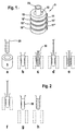
- Figure 1 shows a perspective view of a magnet arrangement according to the invention, in of the four ring magnets (10, 10 ', 10 ", 10' '') are arranged one above the other Ring magnet is formed perpendicular to the ring plane. Located between the ring magnets Spacers (11, 11 ', 11 "). The spacers are made of a non-magnetic Material, for example a plastic. Through the interiors of the stacked Ring magnets is an interior space (12), formed to receive a sample vessel (20). In the arrangement shown, the ring magnets are arranged in the same direction, so that their north-south axis pointing in the same direction.
- FIG. 2 schematically shows the individual process steps for the washing of microparticles shown by means of the magnet arrangement shown in FIG.
- Figure 1a the magnet arrangement shown in perspective, while the remaining figures are cross-sectional drawings.
- a vessel with microparticles suspended therein is placed in the receiving space (12) of the Magnet assembly (5) introduced ( Figures a and b).
- the microparticles through the Magnetic field are deposited on the inner wall of the vessel, which is now in the vessel taken separately from the microparticles liquid with a pipette (30) ( Figure c).
- washing liquid is added ( Figure d) and this in turn from the Vessel pipetted off ( Figure e).
- the vessel is again filled with washing liquid ( Figure f) and Vessel and magnet assembly spatially separated ( Figure g). Now the secluded Cake (50) of microparticles suspended by moving the vessel in the liquid ( Figure h).
- Alternatively to the illustrated method may also be a filling of liquid for resuspending deposited microparticles, including but not limited to this previously the influence of the magnetic field is removed.
- the process of steps a to h can, if necessary to be repeated.
- the Sequence c to f can be repeated as often as desired / required.
- FIG. 3 shows three different magnet arrangements.
- FIG. 3 a shows an arrangement, held together in the opposite polarity by a clip (40) in the three ring magnets become.
- Figure 3b is a corresponding arrangement with 4 oppositely arranged ring magnet shown.
- FIG. 3c shows an arrangement in which between the Ring magnet spacers (11, 11 ') are located.
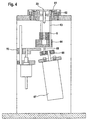
- FIG. 4 shows a system which is suitable both for magnetic separation of microparticles and suitable for resuspending deposited microparticles in liquids.
- a vessel in a holder (61), which is the outer shape of a partial sphere having.
- the partial sphere is held in a stationary mold (62) adapted to its holder.
- the holder is arranged in the mold so that a movement can take place with which the longitudinal axis of the vessel is tilted relative to the vertical.
- the holder Connecting rods (63) which are connected to a movement plate (64).
- the Movement plate also has on its underside a connecting rod (65) which through an eccentric disc (66) is set in a wobbling motion.
- the eccentric disc (66) via a motor (67) set in rotation.
- a magnet arrangement (5) according to FIG. 1 is arranged on the moving plate (64).
- the movement plate can over a lifting device (70) along the connecting rods (63) are moved upward, so that the vessel is immersed in the interior formed by the magnets.
- a separation process can be carried out, in which a vessel in the receiving position is set and the magnet assembly (5) is already arranged so that a lower Area of the vessel dips into its interior or the magnet assembly can on the Lifting device (70) are moved upwards to effect a separation of particles.
- the steps b to f shown in Figure 2 can now be carried out in this position.
- the magnet arrangement (5) is moved to its lower position, which is shown in FIG. 4 is shown, method, and the vessel with its contents by the eccentric in motion offset, so that a resuspension of the microparticles takes place.
Landscapes
- Automatic Analysis And Handling Materials Therefor (AREA)
- Physical Or Chemical Processes And Apparatus (AREA)
- Sampling And Sample Adjustment (AREA)
- Solid-Sorbent Or Filter-Aiding Compositions (AREA)
Applications Claiming Priority (3)
| Application Number | Priority Date | Filing Date | Title |
|---|---|---|---|
| DE10136060 | 2001-07-25 | ||
| DE10136060A DE10136060A1 (de) | 2001-07-25 | 2001-07-25 | System zur Separation von magnetisch anziehbaren Partikeln |
| PCT/EP2002/008174 WO2003009943A1 (de) | 2001-07-25 | 2002-07-23 | System zur separation von magnetisch anziehbaren partikeln |
Publications (2)
| Publication Number | Publication Date |
|---|---|
| EP1420888A1 EP1420888A1 (de) | 2004-05-26 |
| EP1420888B1 true EP1420888B1 (de) | 2005-06-08 |
Family
ID=7692933
Family Applications (1)
| Application Number | Title | Priority Date | Filing Date |
|---|---|---|---|
| EP02767249A Expired - Lifetime EP1420888B1 (de) | 2001-07-25 | 2002-07-23 | System zur separation von magnetisch anziehbaren partikeln |
Country Status (8)
| Country | Link |
|---|---|
| US (1) | US7326350B2 (enExample) |
| EP (1) | EP1420888B1 (enExample) |
| JP (1) | JP3842784B2 (enExample) |
| AT (1) | ATE297255T1 (enExample) |
| CA (1) | CA2453110C (enExample) |
| DE (2) | DE10136060A1 (enExample) |
| ES (1) | ES2242877T3 (enExample) |
| WO (1) | WO2003009943A1 (enExample) |
Families Citing this family (31)
| Publication number | Priority date | Publication date | Assignee | Title |
|---|---|---|---|---|
| AU2003226075B2 (en) | 2002-04-12 | 2008-09-25 | Instrumentation Laboratory Company | Immunoassay probe |
| US8211386B2 (en) | 2004-06-08 | 2012-07-03 | Biokit, S.A. | Tapered cuvette and method of collecting magnetic particles |
| US7535329B2 (en) * | 2005-04-14 | 2009-05-19 | Makrochem, Ltd. | Permanent magnet structure with axial access for spectroscopy applications |
| US7867765B2 (en) | 2005-12-28 | 2011-01-11 | The General Hospital Corporation | Blood cell sorting methods and systems |
| US8268116B2 (en) * | 2007-06-14 | 2012-09-18 | Lam Research Corporation | Methods of and apparatus for protecting a region of process exclusion adjacent to a region of process performance in a process chamber |
| US8795609B2 (en) * | 2007-02-08 | 2014-08-05 | Biokit, S.A. | Magnetic particle washing station |
| JP2008209330A (ja) * | 2007-02-28 | 2008-09-11 | Hitachi High-Technologies Corp | 磁気分離器およびそれを用いた分析装置 |
| US9199247B2 (en) * | 2007-05-29 | 2015-12-01 | Invitrogen Dynal As | Magnetic separation rack |
| GB0724404D0 (en) * | 2007-05-29 | 2008-01-30 | Invitrogen Dynal As | A sample vessel retaining portion |
| JP4586054B2 (ja) * | 2007-08-31 | 2010-11-24 | 株式会社日立ハイテクノロジーズ | 自動分析装置 |
| US8723113B2 (en) * | 2008-05-30 | 2014-05-13 | The State of Oregon Acting by and through the State Board of Higher Education of behalf of Oregon State University | Radio-frequency-free hybrid electrostatic/magnetostatic cell for transporting, trapping, and dissociating ions in mass spectrometers |
| EP2306959A2 (en) * | 2008-07-11 | 2011-04-13 | The General Hospital Corporation | Magnetic apparatus for blood separation |
| EP2208531A1 (en) * | 2008-12-30 | 2010-07-21 | Atonomics A/S | Distribution of particles in capillary channel by application of magnetic field |
| EP2246349A1 (en) | 2009-04-20 | 2010-11-03 | BKG Pharma ApS | Treatment of infectious diseases |
| US20120262260A1 (en) * | 2011-04-18 | 2012-10-18 | Exact Sciences Corporation | Magnetic microparticle localization device |
| JP6297546B2 (ja) * | 2012-06-29 | 2018-03-20 | コーニンクレッカ フィリップス エヌ ヴェKoninklijke Philips N.V. | 結合磁性粒子及び未結合磁性粒子の処理 |
| EP2883237B1 (en) | 2012-08-16 | 2020-11-25 | The State Of Oregon Acting By And Through The State Board Of Higher Education On Behalf Of Oregon State University | Electromagnetostatic electron-induced dissociation cell |
| US9803787B2 (en) * | 2012-09-14 | 2017-10-31 | The United States Of America, As Represented By The Secretary Of The Navy | Magnetically attracted fluid transfer system |
| KR101367122B1 (ko) * | 2012-09-20 | 2014-02-26 | 한국원자력연구원 | 영구자석을 이용한 자기 장치 |
| US20150233932A1 (en) * | 2013-02-19 | 2015-08-20 | Ching-Ping Tseng | Methods, Systems, and Compositions for Enrichment of Rare Cells |
| US9387486B2 (en) * | 2014-09-30 | 2016-07-12 | Ut-Battelle, Llc | High-gradient permanent magnet apparatus and its use in particle collection |
| JP6472973B2 (ja) * | 2014-10-24 | 2019-02-20 | 日本電子株式会社 | 自動分析装置及び分離洗浄方法 |
| CZ306187B6 (cs) * | 2015-02-26 | 2016-09-14 | Univerzita PalackĂ©ho v Olomouci | Zařízení pro magnetickou separaci feromagnetických částic, sada pro magnetickou separaci částic, způsob separace magnetických částic z roztoku a použití zařízení nebo sady pro magnetickou separaci částic |
| CN108474024B (zh) * | 2016-01-05 | 2022-08-02 | 豪夫迈·罗氏有限公司 | 磁性玻璃颗粒对核酸的连续捕获 |
| US11125365B2 (en) | 2018-02-28 | 2021-09-21 | Kohler Co. | Magnetic joint |
| US11408543B2 (en) | 2018-02-28 | 2022-08-09 | Kohler Co. | Articulating faucet |
| US10890277B2 (en) * | 2018-02-28 | 2021-01-12 | Kohler Co. | Articulating faucet with progressive magnetic joint |
| US11214946B2 (en) | 2018-06-04 | 2022-01-04 | Kohler Co. | Articulating faucet |
| US11242675B2 (en) | 2018-06-04 | 2022-02-08 | Kohler Co. | Articulating faucet |
| EP4614158A1 (en) * | 2022-10-31 | 2025-09-10 | FUJIFILM Corporation | Magnetic collecting unit, and testing device |
| EP4614157A1 (en) * | 2022-10-31 | 2025-09-10 | FUJIFILM Corporation | Magnetic collecting unit and test device |
Family Cites Families (9)
| Publication number | Priority date | Publication date | Assignee | Title |
|---|---|---|---|---|
| JPS6253714A (ja) * | 1985-08-30 | 1987-03-09 | Kamata Bio Eng Kk | 流体の磁化浄化装置 |
| JPS6295371A (ja) | 1985-10-22 | 1987-05-01 | Agency Of Ind Science & Technol | 粉末状吸湿架橋性ホツトメルト接着剤の製造方法 |
| EP0479448A3 (en) | 1990-10-02 | 1992-12-23 | Beckman Instruments, Inc. | Magnetic separation device |
| US5897783A (en) | 1992-09-24 | 1999-04-27 | Amersham International Plc | Magnetic separation method |
| US5599501A (en) | 1994-11-10 | 1997-02-04 | Ciba Corning Diagnostics Corp. | Incubation chamber |
| EP0810905B1 (en) * | 1995-02-21 | 1998-11-04 | Iqbal W. Dr. Siddiqi | Apparatus and method for mixing and separation employing magnetic particles |
| US5888835A (en) | 1996-05-10 | 1999-03-30 | Chiron Diagnostics Corporation | Method and apparatus for wash, resuspension, recollection and localization of magnetizable particles in assays using magnetic separation technology |
| US6451207B1 (en) * | 1997-06-04 | 2002-09-17 | Dexter Magnetic Technologies, Inc. | Magnetic cell separation device |
| AU1778701A (en) * | 1999-11-17 | 2001-05-30 | University Of Virginia Patent Foundation | Sperm cell selection system |
-
2001
- 2001-07-25 DE DE10136060A patent/DE10136060A1/de not_active Withdrawn
-
2002
- 2002-07-23 CA CA2453110A patent/CA2453110C/en not_active Expired - Fee Related
- 2002-07-23 WO PCT/EP2002/008174 patent/WO2003009943A1/de not_active Ceased
- 2002-07-23 ES ES02767249T patent/ES2242877T3/es not_active Expired - Lifetime
- 2002-07-23 DE DE50203361T patent/DE50203361D1/de not_active Expired - Lifetime
- 2002-07-23 JP JP2003515326A patent/JP3842784B2/ja not_active Expired - Fee Related
- 2002-07-23 EP EP02767249A patent/EP1420888B1/de not_active Expired - Lifetime
- 2002-07-23 AT AT02767249T patent/ATE297255T1/de active
- 2002-07-23 US US10/484,110 patent/US7326350B2/en not_active Expired - Fee Related
Also Published As
| Publication number | Publication date |
|---|---|
| WO2003009943A8 (de) | 2005-03-03 |
| ATE297255T1 (de) | 2005-06-15 |
| DE10136060A1 (de) | 2003-02-13 |
| JP3842784B2 (ja) | 2006-11-08 |
| ES2242877T3 (es) | 2005-11-16 |
| CA2453110C (en) | 2010-02-09 |
| JP2004535591A (ja) | 2004-11-25 |
| DE50203361D1 (de) | 2005-07-14 |
| US7326350B2 (en) | 2008-02-05 |
| US20040265903A1 (en) | 2004-12-30 |
| EP1420888A1 (de) | 2004-05-26 |
| WO2003009943A1 (de) | 2003-02-06 |
| CA2453110A1 (en) | 2003-02-06 |
Similar Documents
| Publication | Publication Date | Title |
|---|---|---|
| EP1420888B1 (de) | System zur separation von magnetisch anziehbaren partikeln | |
| DE69825890T2 (de) | Magnetische anordnung für zellen-trennung und verfahren zur trennung | |
| DE69126541T2 (de) | Vorrichtung und verfahren für die magnetische trennung | |
| DE69329135T2 (de) | Verfahren und Vorrichtung zur magnetischen Abscheidung | |
| EP0691541B1 (de) | Verfahren zum Abscheiden von magnetischen Mikropartikeln | |
| DE69222299T2 (de) | Vorrichtung und verfahren zur magnetischen abtrennung unter verwendung externer magnetischer mittel | |
| DE68919715T2 (de) | Verfahren sowie materialien zur hochgraduierten magnetischen abspaltung biologischer materialien. | |
| DE10057396C1 (de) | Verfahren zum Abtrennen eines dispergierten oder gelösten Stoffes und Magnetseparator | |
| EP1446668B1 (de) | Vorrichtung und verfahren zum behandeln von magnetpartikeln | |
| EP2033715B1 (de) | Verfahren zum Suspendieren oder Resuspendieren von Partikeln in einer Lösung sowie daran angepasste Vorrichtung | |
| DE69701418T2 (de) | Verfahren und Vorrichtung zum Waschen, zur Resuspension, zum Wiedersammeln und zur Lokalisierung von magnetisierbaren Teilchen in der magnetischen Trennungstechnik von Proben | |
| DE60026729T2 (de) | Verfahren zur modifikation von ausgewählten zellen in einer magnetischen zelltrennungsäule | |
| EP1919625B1 (de) | Vorrichtung und verfahren zum abtrennen von magnetischen partikeln aus einer flüssigkeit | |
| EP3687685A1 (de) | Vorrichtung und verfahren zur immobilisierung von biomolekülen mit magnetischen partikeln | |
| EP1685404B1 (de) | Verfahren und vorrichtung zur verbesserten reinigung einer an paramagnetische mikropartikel gebundenen substanz | |
| DE10063984A1 (de) | Vorrichtungen zur magnetischen Abtrennung von Magnetpartikeln | |
| EP2129466B1 (de) | Manipulationseinrichtung und manipulationsverfahren für eine biologische probe | |
| DE102015013851B3 (de) | Methode zur verbesserten magnetischen Markierung von biologischen Materialien | |
| DE102021006144A1 (de) | Reaktionsgefäßeinheit, Verfahren zum selektiven Entfernen einer Flüssigkeit sowie zum Einbringen einer einen Zielstoff enthaltenden Flüssigkeit aus einem bzw. in ein Reaktionsgefäß einer Reaktionsgefäßeinheit | |
| DE202021105458U1 (de) | Vorrichtung zur magnetischen Aufreinigung biologischer Proben | |
| DE10231925A1 (de) | Reaktorsystem zur Durchführung chemischer und biochemischer Prozesse | |
| DE19955169A1 (de) | Verfahren und Vorrichtung zur Ausübung einer Kraft auf magnetische Partikel | |
| EP3147028B1 (de) | Verfahren und system zur magnetischen trennung von nano-beads | |
| DE19834584A1 (de) | Vorrichtung zur magnetischen Aufreinigung von biologischen Materialien | |
| WO2007137749A1 (de) | Verfahren zum nachweis von antikörpern und/oder antigenen sowie zur blutgruppenbestimmung in einer testsubstanz |
Legal Events
| Date | Code | Title | Description |
|---|---|---|---|
| PUAI | Public reference made under article 153(3) epc to a published international application that has entered the european phase |
Free format text: ORIGINAL CODE: 0009012 |
|
| 17P | Request for examination filed |
Effective date: 20040224 |
|
| AK | Designated contracting states |
Kind code of ref document: A1 Designated state(s): AT BE BG CH CY CZ DE DK EE ES FI FR GB GR IE IT LI LU MC NL PT SE SK TR |
|
| AX | Request for extension of the european patent |
Extension state: AL LT LV MK RO SI |
|
| 17Q | First examination report despatched |
Effective date: 20040730 |
|
| GRAP | Despatch of communication of intention to grant a patent |
Free format text: ORIGINAL CODE: EPIDOSNIGR1 |
|
| RAP1 | Party data changed (applicant data changed or rights of an application transferred) |
Owner name: F.HOFFMANN-LA ROCHE AG Owner name: ROCHE DIAGNOSTICS GMBH |
|
| GRAS | Grant fee paid |
Free format text: ORIGINAL CODE: EPIDOSNIGR3 |
|
| GRAA | (expected) grant |
Free format text: ORIGINAL CODE: 0009210 |
|
| AK | Designated contracting states |
Kind code of ref document: B1 Designated state(s): AT BE BG CH CY CZ DE DK EE ES FI FR GB GR IE IT LI LU MC NL PT SE SK TR |
|
| PG25 | Lapsed in a contracting state [announced via postgrant information from national office to epo] |
Ref country code: CZ Free format text: LAPSE BECAUSE OF FAILURE TO SUBMIT A TRANSLATION OF THE DESCRIPTION OR TO PAY THE FEE WITHIN THE PRESCRIBED TIME-LIMIT Effective date: 20050608 Ref country code: FI Free format text: LAPSE BECAUSE OF FAILURE TO SUBMIT A TRANSLATION OF THE DESCRIPTION OR TO PAY THE FEE WITHIN THE PRESCRIBED TIME-LIMIT Effective date: 20050608 Ref country code: TR Free format text: LAPSE BECAUSE OF FAILURE TO SUBMIT A TRANSLATION OF THE DESCRIPTION OR TO PAY THE FEE WITHIN THE PRESCRIBED TIME-LIMIT Effective date: 20050608 Ref country code: EE Free format text: LAPSE BECAUSE OF FAILURE TO SUBMIT A TRANSLATION OF THE DESCRIPTION OR TO PAY THE FEE WITHIN THE PRESCRIBED TIME-LIMIT Effective date: 20050608 Ref country code: SK Free format text: LAPSE BECAUSE OF FAILURE TO SUBMIT A TRANSLATION OF THE DESCRIPTION OR TO PAY THE FEE WITHIN THE PRESCRIBED TIME-LIMIT Effective date: 20050608 Ref country code: IE Free format text: LAPSE BECAUSE OF FAILURE TO SUBMIT A TRANSLATION OF THE DESCRIPTION OR TO PAY THE FEE WITHIN THE PRESCRIBED TIME-LIMIT Effective date: 20050608 Ref country code: NL Free format text: LAPSE BECAUSE OF FAILURE TO SUBMIT A TRANSLATION OF THE DESCRIPTION OR TO PAY THE FEE WITHIN THE PRESCRIBED TIME-LIMIT Effective date: 20050608 |
|
| REG | Reference to a national code |
Ref country code: GB Ref legal event code: FG4D Free format text: NOT ENGLISH |
|
| REG | Reference to a national code |
Ref country code: CH Ref legal event code: EP Ref country code: CH Ref legal event code: NV Representative=s name: A. BRAUN, BRAUN, HERITIER, ESCHMANN AG PATENTANWAE |
|
| GBT | Gb: translation of ep patent filed (gb section 77(6)(a)/1977) |
Effective date: 20050608 |
|
| REF | Corresponds to: |
Ref document number: 50203361 Country of ref document: DE Date of ref document: 20050714 Kind code of ref document: P |
|
| PG25 | Lapsed in a contracting state [announced via postgrant information from national office to epo] |
Ref country code: CY Free format text: LAPSE BECAUSE OF FAILURE TO SUBMIT A TRANSLATION OF THE DESCRIPTION OR TO PAY THE FEE WITHIN THE PRESCRIBED TIME-LIMIT Effective date: 20050723 Ref country code: LU Free format text: LAPSE BECAUSE OF NON-PAYMENT OF DUE FEES Effective date: 20050723 |
|
| REG | Reference to a national code |
Ref country code: IE Ref legal event code: FG4D Free format text: LANGUAGE OF EP DOCUMENT: GERMAN |
|
| PG25 | Lapsed in a contracting state [announced via postgrant information from national office to epo] |
Ref country code: MC Free format text: LAPSE BECAUSE OF NON-PAYMENT OF DUE FEES Effective date: 20050731 Ref country code: BE Free format text: LAPSE BECAUSE OF NON-PAYMENT OF DUE FEES Effective date: 20050731 |
|
| PG25 | Lapsed in a contracting state [announced via postgrant information from national office to epo] |
Ref country code: SE Free format text: LAPSE BECAUSE OF FAILURE TO SUBMIT A TRANSLATION OF THE DESCRIPTION OR TO PAY THE FEE WITHIN THE PRESCRIBED TIME-LIMIT Effective date: 20050908 Ref country code: BG Free format text: LAPSE BECAUSE OF FAILURE TO SUBMIT A TRANSLATION OF THE DESCRIPTION OR TO PAY THE FEE WITHIN THE PRESCRIBED TIME-LIMIT Effective date: 20050908 Ref country code: DK Free format text: LAPSE BECAUSE OF FAILURE TO SUBMIT A TRANSLATION OF THE DESCRIPTION OR TO PAY THE FEE WITHIN THE PRESCRIBED TIME-LIMIT Effective date: 20050908 Ref country code: GR Free format text: LAPSE BECAUSE OF FAILURE TO SUBMIT A TRANSLATION OF THE DESCRIPTION OR TO PAY THE FEE WITHIN THE PRESCRIBED TIME-LIMIT Effective date: 20050908 |
|
| PG25 | Lapsed in a contracting state [announced via postgrant information from national office to epo] |
Ref country code: PT Free format text: LAPSE BECAUSE OF FAILURE TO SUBMIT A TRANSLATION OF THE DESCRIPTION OR TO PAY THE FEE WITHIN THE PRESCRIBED TIME-LIMIT Effective date: 20051108 |
|
| REG | Reference to a national code |
Ref country code: ES Ref legal event code: FG2A Ref document number: 2242877 Country of ref document: ES Kind code of ref document: T3 |
|
| NLV1 | Nl: lapsed or annulled due to failure to fulfill the requirements of art. 29p and 29m of the patents act | ||
| REG | Reference to a national code |
Ref country code: IE Ref legal event code: FD4D |
|
| ET | Fr: translation filed | ||
| PLBE | No opposition filed within time limit |
Free format text: ORIGINAL CODE: 0009261 |
|
| STAA | Information on the status of an ep patent application or granted ep patent |
Free format text: STATUS: NO OPPOSITION FILED WITHIN TIME LIMIT |
|
| 26N | No opposition filed |
Effective date: 20060309 |
|
| BERE | Be: lapsed |
Owner name: F.HOFFMANN-LA ROCHE A.G. Effective date: 20050731 Owner name: ROCHE DIAGNOSTICS G.M.B.H. Effective date: 20050731 |
|
| REG | Reference to a national code |
Ref country code: CH Ref legal event code: PFA Owner name: F.HOFFMANN-LA ROCHE AG Free format text: F.HOFFMANN-LA ROCHE AG#GRENZACHERSTRASSE 124#4070 BASEL (CH) -TRANSFER TO- F.HOFFMANN-LA ROCHE AG#GRENZACHERSTRASSE 124#4070 BASEL (CH) |
|
| REG | Reference to a national code |
Ref country code: CH Ref legal event code: PCAR Free format text: NEW ADDRESS: HOLBEINSTRASSE 36-38, 4051 BASEL (CH) |
|
| PGFP | Annual fee paid to national office [announced via postgrant information from national office to epo] |
Ref country code: AT Payment date: 20150624 Year of fee payment: 14 |
|
| REG | Reference to a national code |
Ref country code: FR Ref legal event code: PLFP Year of fee payment: 15 |
|
| PGFP | Annual fee paid to national office [announced via postgrant information from national office to epo] |
Ref country code: GB Payment date: 20160624 Year of fee payment: 15 |
|
| PGFP | Annual fee paid to national office [announced via postgrant information from national office to epo] |
Ref country code: FR Payment date: 20160621 Year of fee payment: 15 |
|
| PGFP | Annual fee paid to national office [announced via postgrant information from national office to epo] |
Ref country code: IT Payment date: 20160720 Year of fee payment: 15 Ref country code: DE Payment date: 20160801 Year of fee payment: 15 Ref country code: CH Payment date: 20160725 Year of fee payment: 15 |
|
| PGFP | Annual fee paid to national office [announced via postgrant information from national office to epo] |
Ref country code: ES Payment date: 20160708 Year of fee payment: 15 |
|
| REG | Reference to a national code |
Ref country code: AT Ref legal event code: MM01 Ref document number: 297255 Country of ref document: AT Kind code of ref document: T Effective date: 20160723 |
|
| PG25 | Lapsed in a contracting state [announced via postgrant information from national office to epo] |
Ref country code: AT Free format text: LAPSE BECAUSE OF NON-PAYMENT OF DUE FEES Effective date: 20160723 |
|
| REG | Reference to a national code |
Ref country code: DE Ref legal event code: R119 Ref document number: 50203361 Country of ref document: DE |
|
| REG | Reference to a national code |
Ref country code: CH Ref legal event code: PL |
|
| GBPC | Gb: european patent ceased through non-payment of renewal fee |
Effective date: 20170723 |
|
| REG | Reference to a national code |
Ref country code: FR Ref legal event code: ST Effective date: 20180330 |
|
| PG25 | Lapsed in a contracting state [announced via postgrant information from national office to epo] |
Ref country code: GB Free format text: LAPSE BECAUSE OF NON-PAYMENT OF DUE FEES Effective date: 20170723 Ref country code: DE Free format text: LAPSE BECAUSE OF NON-PAYMENT OF DUE FEES Effective date: 20180201 Ref country code: CH Free format text: LAPSE BECAUSE OF NON-PAYMENT OF DUE FEES Effective date: 20170731 Ref country code: LI Free format text: LAPSE BECAUSE OF NON-PAYMENT OF DUE FEES Effective date: 20170731 |
|
| PG25 | Lapsed in a contracting state [announced via postgrant information from national office to epo] |
Ref country code: FR Free format text: LAPSE BECAUSE OF NON-PAYMENT OF DUE FEES Effective date: 20170731 |
|
| PG25 | Lapsed in a contracting state [announced via postgrant information from national office to epo] |
Ref country code: IT Free format text: LAPSE BECAUSE OF NON-PAYMENT OF DUE FEES Effective date: 20170723 |
|
| REG | Reference to a national code |
Ref country code: ES Ref legal event code: FD2A Effective date: 20181030 |
|
| PG25 | Lapsed in a contracting state [announced via postgrant information from national office to epo] |
Ref country code: ES Free format text: LAPSE BECAUSE OF NON-PAYMENT OF DUE FEES Effective date: 20170724 |