EP1420888B1 - System for separating magnetically attractable particles - Google Patents
System for separating magnetically attractable particles Download PDFInfo
- Publication number
- EP1420888B1 EP1420888B1 EP02767249A EP02767249A EP1420888B1 EP 1420888 B1 EP1420888 B1 EP 1420888B1 EP 02767249 A EP02767249 A EP 02767249A EP 02767249 A EP02767249 A EP 02767249A EP 1420888 B1 EP1420888 B1 EP 1420888B1
- Authority
- EP
- European Patent Office
- Prior art keywords
- vessel
- microparticles
- magnets
- ring
- separation
- Prior art date
- Legal status (The legal status is an assumption and is not a legal conclusion. Google has not performed a legal analysis and makes no representation as to the accuracy of the status listed.)
- Expired - Lifetime
Links
- 239000002245 particle Substances 0.000 title claims description 39
- 239000011859 microparticle Substances 0.000 claims abstract description 37
- 238000000926 separation method Methods 0.000 claims abstract description 30
- 239000007788 liquid Substances 0.000 claims abstract description 23
- 238000000034 method Methods 0.000 claims abstract description 13
- 239000000725 suspension Substances 0.000 claims abstract description 13
- 230000005291 magnetic effect Effects 0.000 claims description 27
- 125000006850 spacer group Chemical group 0.000 claims description 6
- 230000008021 deposition Effects 0.000 claims description 4
- 230000027455 binding Effects 0.000 claims description 3
- 230000001900 immune effect Effects 0.000 claims description 3
- 239000000696 magnetic material Substances 0.000 claims description 3
- 230000004308 accommodation Effects 0.000 claims 1
- 238000005406 washing Methods 0.000 description 12
- 239000011159 matrix material Substances 0.000 description 6
- 239000000126 substance Substances 0.000 description 6
- 238000006243 chemical reaction Methods 0.000 description 5
- 239000012491 analyte Substances 0.000 description 3
- 238000000576 coating method Methods 0.000 description 3
- 239000006249 magnetic particle Substances 0.000 description 3
- YBJHBAHKTGYVGT-ZKWXMUAHSA-N (+)-Biotin Chemical compound N1C(=O)N[C@@H]2[C@H](CCCCC(=O)O)SC[C@@H]21 YBJHBAHKTGYVGT-ZKWXMUAHSA-N 0.000 description 2
- 230000005294 ferromagnetic effect Effects 0.000 description 2
- 239000012530 fluid Substances 0.000 description 2
- 230000005389 magnetism Effects 0.000 description 2
- 239000006228 supernatant Substances 0.000 description 2
- FGUUSXIOTUKUDN-IBGZPJMESA-N C1(=CC=CC=C1)N1C2=C(NC([C@H](C1)NC=1OC(=NN=1)C1=CC=CC=C1)=O)C=CC=C2 Chemical compound C1(=CC=CC=C1)N1C2=C(NC([C@H](C1)NC=1OC(=NN=1)C1=CC=CC=C1)=O)C=CC=C2 FGUUSXIOTUKUDN-IBGZPJMESA-N 0.000 description 1
- 108010090804 Streptavidin Proteins 0.000 description 1
- 230000000712 assembly Effects 0.000 description 1
- 238000000429 assembly Methods 0.000 description 1
- 239000011230 binding agent Substances 0.000 description 1
- 230000015572 biosynthetic process Effects 0.000 description 1
- 229960002685 biotin Drugs 0.000 description 1
- 235000020958 biotin Nutrition 0.000 description 1
- 239000011616 biotin Substances 0.000 description 1
- 239000008280 blood Substances 0.000 description 1
- 210000004369 blood Anatomy 0.000 description 1
- 239000012295 chemical reaction liquid Substances 0.000 description 1
- 238000004140 cleaning Methods 0.000 description 1
- 239000011248 coating agent Substances 0.000 description 1
- 238000001514 detection method Methods 0.000 description 1
- 230000029087 digestion Effects 0.000 description 1
- 238000010790 dilution Methods 0.000 description 1
- 239000012895 dilution Substances 0.000 description 1
- 238000009826 distribution Methods 0.000 description 1
- 230000000694 effects Effects 0.000 description 1
- 230000002349 favourable effect Effects 0.000 description 1
- 238000003780 insertion Methods 0.000 description 1
- 230000037431 insertion Effects 0.000 description 1
- 238000007885 magnetic separation Methods 0.000 description 1
- 238000004519 manufacturing process Methods 0.000 description 1
- 239000000463 material Substances 0.000 description 1
- 230000005298 paramagnetic effect Effects 0.000 description 1
- 210000002966 serum Anatomy 0.000 description 1
- 230000009870 specific binding Effects 0.000 description 1
- 238000003860 storage Methods 0.000 description 1
Images

Classifications
-
- B—PERFORMING OPERATIONS; TRANSPORTING
- B03—SEPARATION OF SOLID MATERIALS USING LIQUIDS OR USING PNEUMATIC TABLES OR JIGS; MAGNETIC OR ELECTROSTATIC SEPARATION OF SOLID MATERIALS FROM SOLID MATERIALS OR FLUIDS; SEPARATION BY HIGH-VOLTAGE ELECTRIC FIELDS
- B03C—MAGNETIC OR ELECTROSTATIC SEPARATION OF SOLID MATERIALS FROM SOLID MATERIALS OR FLUIDS; SEPARATION BY HIGH-VOLTAGE ELECTRIC FIELDS
- B03C1/00—Magnetic separation
- B03C1/02—Magnetic separation acting directly on the substance being separated
- B03C1/28—Magnetic plugs and dipsticks
- B03C1/288—Magnetic plugs and dipsticks disposed at the outer circumference of a recipient
-
- B—PERFORMING OPERATIONS; TRANSPORTING
- B03—SEPARATION OF SOLID MATERIALS USING LIQUIDS OR USING PNEUMATIC TABLES OR JIGS; MAGNETIC OR ELECTROSTATIC SEPARATION OF SOLID MATERIALS FROM SOLID MATERIALS OR FLUIDS; SEPARATION BY HIGH-VOLTAGE ELECTRIC FIELDS
- B03C—MAGNETIC OR ELECTROSTATIC SEPARATION OF SOLID MATERIALS FROM SOLID MATERIALS OR FLUIDS; SEPARATION BY HIGH-VOLTAGE ELECTRIC FIELDS
- B03C1/00—Magnetic separation
- B03C1/02—Magnetic separation acting directly on the substance being separated
- B03C1/035—Open gradient magnetic separators, i.e. separators in which the gap is unobstructed, characterised by the configuration of the gap
-
- B—PERFORMING OPERATIONS; TRANSPORTING
- B03—SEPARATION OF SOLID MATERIALS USING LIQUIDS OR USING PNEUMATIC TABLES OR JIGS; MAGNETIC OR ELECTROSTATIC SEPARATION OF SOLID MATERIALS FROM SOLID MATERIALS OR FLUIDS; SEPARATION BY HIGH-VOLTAGE ELECTRIC FIELDS
- B03C—MAGNETIC OR ELECTROSTATIC SEPARATION OF SOLID MATERIALS FROM SOLID MATERIALS OR FLUIDS; SEPARATION BY HIGH-VOLTAGE ELECTRIC FIELDS
- B03C2201/00—Details of magnetic or electrostatic separation
- B03C2201/26—Details of magnetic or electrostatic separation for use in medical or biological applications
-
- G—PHYSICS
- G01—MEASURING; TESTING
- G01N—INVESTIGATING OR ANALYSING MATERIALS BY DETERMINING THEIR CHEMICAL OR PHYSICAL PROPERTIES
- G01N35/00—Automatic analysis not limited to methods or materials provided for in any single one of groups G01N1/00 - G01N33/00; Handling materials therefor
- G01N35/0098—Automatic analysis not limited to methods or materials provided for in any single one of groups G01N1/00 - G01N33/00; Handling materials therefor involving analyte bound to insoluble magnetic carrier, e.g. using magnetic separation
Definitions
- the present invention falls within the field of analysis, in particular clinical and immunological analysis using magnetically attractable particles.
- the invention relates to a system for the separation of magnetically attractable particles, which in a liquid containing a magnet assembly having at least two annular ones Magnets whose magnetic axis is aligned perpendicular to the ring plane, the magnets are arranged in the same direction or in opposite directions one above the other and the ring interiors a receiving position to form a vessel.
- the invention further relates to methods for separation and Washing of magnetically attractable particles using such a system, as well System having a motion device for suspending separated particles.
- the magnetically attractable particles are in primarily used for the separation of substances / particles to be detected from the sample matrix.
- the magnetically attractable particles are coated so that they either directly or bind after reaction with auxiliary substances to be detected material on their surface. at These processes are intentional or mandatory, the substance to be detected as possible completely separate from the sample matrix so that subsequent analytical steps are not disturbed become. Separation of the magnetically attractable particles from the sample matrix is particularly important to be able to wash the particles and thus an even further separation to achieve the sample matrix.
- a Separationsdevice which is a magnetic disk having holes, introduced into the vessels with suspended magnetic particles contained therein become.
- the magnetic plate is such that the north-south axis parallel to Axis of the bore is arranged.
- the document JP 62053714 describes an arrangement which comprises a plurality of annular magnet having its magnetic axis perpendicular to the ring plane is aligned and their ring interiors form a space.
- the annular magnets arranged so that the magnets in the same direction one above the other are arranged, so in each case the north pole of the one ring to the south pole of the other Ringes adjoins.
- Magnetically attractable particles in the sense of the present invention are both paramagnetic and preferably ferromagnetic particles.
- the ferromagnetic particles are magnetically hard substances, which after removal of an external magnetic field no or have only a low residual magnetism, preferably. Remaining residual magnetism would make a complete resuspension of the particles more difficult.
- Magnetically attractable Microparticles for use in the analysis typically have a diameter in the range of a few micrometers, preferably in the range of 1.5-4 ⁇ m. Such particles can be obtained commercially, for example, from Dynal.
- the particles are usually coated with binding partners. This Both coatings can be those that directly bind an analyte to be detected also universal coatings, such. B.
- streptavidin By reaction universally coated Particles with conjugates from a binding agent for the universal coating (for example Biotin) and a binding partner for the analyte, may be specific binding microparticles be generated.
- a binding agent for the universal coating for example Biotin
- a binding partner for the analyte for example Biotin
- the production process for microparticles for chemical / immunological Analysis in the prior art are well known, is not at this point closer received.
- the microparticles are mixed with a sample fluid such as blood or serum, to bind analytes to be detected on the surface of the microparticles or can cause a specific reaction there.
- a sample fluid such as blood or serum
- Both microparticles and sample fluid can before the described reaction step other operations such as suspension, dilution, digestion, etc. are subjected.
- an analysis requires that part of the sample that is not analyte (Sample matrix) as completely as possible to separate, a disturbance of later detection reactions to avoid. In the field of the invention this is done by separation of the magnetic attractable particles and separation of the remaining liquid (in general parlance also called supernatant).
- the separated microparticles must be carried out before further analysis steps are first washed to adhering liquid, the also contains sample matrix to remove.
- Such a washing can according to the invention both take place while the particles are deposited as well as through or while the particles suspended in liquid.
- the present invention is characterized Invention characterized in that the microparticles are deposited in a mold from which they can be resuspended particularly well and without retaining larger aggregates.
- the Particles can now be used in a variety of ways for analysis.
- a suspension of magnetic microparticles in the effective field of the magnet arrangement d. H. in the given case in the interior of the annular Magnets are introduced.
- This can be achieved primarily by a non-magnetic
- the magnet arrangement be moved so that the vessel is immersed with the suspension in the interior.
- Another Possibility then to choose a magnet arrangement consisting of two or more parts, preferably two half-shells, constructed which moves apart for insertion of a vessel, the vessel placed in the formed interior and the parts for applying the Magnetic field are moved together.
- the annular magnets of a magnet arrangement according to the invention can be in the same direction or arranged in opposite directions one above the other.
- An opposing orientation leads to stronger ones Magnetic field gradients and thus to a faster separation of particles.
- a reduction in the separation time is in principle favorable in order to reducing the time needed for the analysis process, but also often with a more difficult one connected resuspending particle cake.
- an arrangement arranged in opposite directions Magnets chosen so it is advantageous to provide a holding device that holds the magnets holds together against the repulsion.
- Both in the same direction as in opposite directions Orientation of the magnets can provide spacers between the individual magnets be made of non-magnetic material. By selecting the spacers, In particular, its thickness, the intensity and spatial distribution of the magnetic field on be modified in a simpler way. So it is simply possible, the magnet assembly the to adapt to respective requirements.
- the interior of the ring into which a vessel for Separation is introduced preferably a cross section in the range between 4 and 10 mm should have. It is also advantageous if the individual, for the magnet arrangement used magnets have a magnetic remanence greater than 0.8 T. such Ring magnets can be obtained for example via the company Bomatec, Höri in Switzerland.
- annular magnets are preferred because they have a homogeneous Separation of the particles can be achieved at the vessel inner wall. It is, however in principle also magnets with other, annular closed magnets, e.g. in the form of one Rectangles or polygons, possible. Ring interior and vessel outer surface are preferably so matched to each other, that between Magnetinnenwandung and vessel outer wall, a gap of preferably 0 to 1.5 mm, better still less than 0.5 mm remains when the respective vessel concentric is introduced into the ring magnet.
- a device for resuspension of deposited microparticles which are advantageous in a system for separation with Magnetic arrangement according to the invention can be used.
- the device for suspending deposited microparticles has a vial holder for receiving a vessel.
- the vessel holder is used to suspend particles a moving device moves.
- the vessel holder is mounted so that in a way in which the vessel axis is tilted relative to the Lot.
- a Such storage may, for example, by a vessel holder with an outer surface in Form of a spherical segment can be achieved, which in a corresponding cavity, the has a depression in the form of a partial sphere, is held.
- a movement of the vessel holder can be done by a mechanical connection with an eccentric drive.
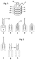
- Figure 1 shows a perspective view of a magnet arrangement according to the invention, in of the four ring magnets (10, 10 ', 10 ", 10' '') are arranged one above the other Ring magnet is formed perpendicular to the ring plane. Located between the ring magnets Spacers (11, 11 ', 11 "). The spacers are made of a non-magnetic Material, for example a plastic. Through the interiors of the stacked Ring magnets is an interior space (12), formed to receive a sample vessel (20). In the arrangement shown, the ring magnets are arranged in the same direction, so that their north-south axis pointing in the same direction.
- FIG. 2 schematically shows the individual process steps for the washing of microparticles shown by means of the magnet arrangement shown in FIG.
- Figure 1a the magnet arrangement shown in perspective, while the remaining figures are cross-sectional drawings.
- a vessel with microparticles suspended therein is placed in the receiving space (12) of the Magnet assembly (5) introduced ( Figures a and b).
- the microparticles through the Magnetic field are deposited on the inner wall of the vessel, which is now in the vessel taken separately from the microparticles liquid with a pipette (30) ( Figure c).
- washing liquid is added ( Figure d) and this in turn from the Vessel pipetted off ( Figure e).
- the vessel is again filled with washing liquid ( Figure f) and Vessel and magnet assembly spatially separated ( Figure g). Now the secluded Cake (50) of microparticles suspended by moving the vessel in the liquid ( Figure h).
- Alternatively to the illustrated method may also be a filling of liquid for resuspending deposited microparticles, including but not limited to this previously the influence of the magnetic field is removed.
- the process of steps a to h can, if necessary to be repeated.
- the Sequence c to f can be repeated as often as desired / required.
- FIG. 3 shows three different magnet arrangements.
- FIG. 3 a shows an arrangement, held together in the opposite polarity by a clip (40) in the three ring magnets become.
- Figure 3b is a corresponding arrangement with 4 oppositely arranged ring magnet shown.
- FIG. 3c shows an arrangement in which between the Ring magnet spacers (11, 11 ') are located.
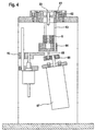
- FIG. 4 shows a system which is suitable both for magnetic separation of microparticles and suitable for resuspending deposited microparticles in liquids.
- a vessel in a holder (61), which is the outer shape of a partial sphere having.
- the partial sphere is held in a stationary mold (62) adapted to its holder.
- the holder is arranged in the mold so that a movement can take place with which the longitudinal axis of the vessel is tilted relative to the vertical.
- the holder Connecting rods (63) which are connected to a movement plate (64).
- the Movement plate also has on its underside a connecting rod (65) which through an eccentric disc (66) is set in a wobbling motion.
- the eccentric disc (66) via a motor (67) set in rotation.
- a magnet arrangement (5) according to FIG. 1 is arranged on the moving plate (64).
- the movement plate can over a lifting device (70) along the connecting rods (63) are moved upward, so that the vessel is immersed in the interior formed by the magnets.
- a separation process can be carried out, in which a vessel in the receiving position is set and the magnet assembly (5) is already arranged so that a lower Area of the vessel dips into its interior or the magnet assembly can on the Lifting device (70) are moved upwards to effect a separation of particles.
- the steps b to f shown in Figure 2 can now be carried out in this position.
- the magnet arrangement (5) is moved to its lower position, which is shown in FIG. 4 is shown, method, and the vessel with its contents by the eccentric in motion offset, so that a resuspension of the microparticles takes place.
Landscapes
- Automatic Analysis And Handling Materials Therefor (AREA)
- Physical Or Chemical Processes And Apparatus (AREA)
- Sampling And Sample Adjustment (AREA)
- Solid-Sorbent Or Filter-Aiding Compositions (AREA)
Abstract
Description
Die vorliegende Erfindung fällt in das Gebiet der Analytik, insbesondere der klinischen und immunologischen Analytik unter Verwendung magnetisch anziehbarer Partikel.The present invention falls within the field of analysis, in particular clinical and immunological analysis using magnetically attractable particles.
Die Erfindung betrifft ein System zur Separation von magnetisch anziehbaren Partikeln, die in einer Flüssigkeit suspendiert sind, beinhaltend eine Magnetanordnung mit mindestens zwei ringförmigen Magneten, deren Magnetachse senkrecht zur Ringebene ausgerichtet ist, die Magnete gleichsinnig oder gegensinnig übereinander angeordnet sind und die Ringinnenräume eine Aufnahmeposition für ein Gefäß bilden. Die Erfindung betrifft ferner Verfahren zur Separation und Waschung magnetisch anziehbarer Partikel unter Verwendung eines solchen Systems, sowie ein System, das eine Bewegungsvorrichtung zur Suspendierung separierter Partikel besitzt.The invention relates to a system for the separation of magnetically attractable particles, which in a liquid containing a magnet assembly having at least two annular ones Magnets whose magnetic axis is aligned perpendicular to the ring plane, the magnets are arranged in the same direction or in opposite directions one above the other and the ring interiors a receiving position to form a vessel. The invention further relates to methods for separation and Washing of magnetically attractable particles using such a system, as well System having a motion device for suspending separated particles.
Im Gebiet der chemischen Analyse hat sich eine Verwendung von magnetisch anziehbaren Partikeln bereits seit einiger Zeit etabliert. Die magnetisch anziehbaren Partikel werden dabei in erster Linie zur Abtrennung nachzuweisender Stoffe / Partikel aus der Probenmatrix eingesetzt. Hierzu werden die magnetisch anziehbaren Partikel so beschichtet, daß sie entweder direkt oder nach Reaktion mit Hilfssubstanzen nachzuweisendes Material auf ihrer Oberfläche binden. Bei diesen Prozessen ist es gewollt oder zwingend notwendig, nachzuweisende Substanz möglichst vollständig von der Probenmatrix zu trennen, damit spätere analytische Schritte nicht gestört werden. Eine Abtrennung der magnetisch anziehbaren Partikel von der Probenmatrix ist insbesondere wichtig, um die Partikel waschen zu können und so eine noch weitergehende Abtrennung der Probenmatrix zu erzielen.In the field of chemical analysis, there has been a use of magnetically attractable particles already established for some time. The magnetically attractable particles are in primarily used for the separation of substances / particles to be detected from the sample matrix. For this purpose, the magnetically attractable particles are coated so that they either directly or bind after reaction with auxiliary substances to be detected material on their surface. at These processes are intentional or mandatory, the substance to be detected as possible completely separate from the sample matrix so that subsequent analytical steps are not disturbed become. Separation of the magnetically attractable particles from the sample matrix is particularly important to be able to wash the particles and thus an even further separation to achieve the sample matrix.
In den Dokumenten US 5,827,478 und US 5,888,835 sind Anordnungen beschrieben, bei denen Magnetpartikel, die sich in Suspension befinden, durch Heranführen von Magneten an eine Gefäßaußenseite separiert werden. Überstehende Probenflüssigkeit wird aus dem Gefäß entfernt und die Partikel werden mit einer Reinigungsflüssigkeit gewaschen. Hierzu können die Partikel nach Abtrennung des Überstandes in einer Waschflüssigkeit suspendiert werden. In the documents US 5,827,478 and US 5,888,835 arrangements are described in which Magnetic particles in suspension by bringing magnets to a vessel outside be separated. Excess sample liquid is removed from the vessel and the particles are washed with a cleaning liquid. For this purpose, the particles be suspended after separation of the supernatant in a washing liquid.
In den Dokumenten US 5,976,369 und US 5,897,783 sind Anordnungen beschrieben, bei denen Magnetpartikel durch einen magnetischen Dipol an der Innenwandung eines Gefäßes abgeschieden werden. Durch die Formgebung des magnetischen Jochs wird eine Separation erzielt, bei der die Partikel im wesentlichen in Form eines Ringes abgeschieden werden. Bei Verwendung eines Dipoles dieser Art ist jedoch die Ausbildung eines homogenen Ringes nicht möglich.In the documents US 5,976,369 and US 5,897,783 arrangements are described in which Magnetic particles deposited by a magnetic dipole on the inner wall of a vessel become. Due to the shape of the magnetic yoke, a separation is achieved in which the particles are deposited substantially in the form of a ring. When using a Dipoles of this kind, however, the formation of a homogeneous ring is not possible.
Aus der EP 0 479 448 ist weiterhin ein Separationsdevice bekannt, welches eine Magnetplatte mit Bohrungen aufweist, in die Gefäße mit darin enthaltenen suspendierten Magnetpartikeln eingebracht werden. Die Magnetplatte ist so beschaffen, daß die Nord-Süd-Achse parallel zur Achse der Bohrung angeordnet ist.From EP 0 479 448 a Separationsdevice is also known, which is a magnetic disk having holes, introduced into the vessels with suspended magnetic particles contained therein become. The magnetic plate is such that the north-south axis parallel to Axis of the bore is arranged.
Im Dokument JP 62053714 ist eine Anordnung beschrieben, welche eine Mehrzahl von ringförmigen Magneten aufweist, deren Magnetachse senkrecht zur Ringebene ausgerichtet ist und deren Ringinnenräume einen Raum bilden. Bei dieser Anordnung sind die ringförmigen Magnete so angeordnet, dass die Magnete gleichsinnig übereinander angeordnet sind, also jeweils der Nordpol des einen Ringes an den Südpol des anderen Ringes angrenzt.The document JP 62053714 describes an arrangement which comprises a plurality of annular magnet having its magnetic axis perpendicular to the ring plane is aligned and their ring interiors form a space. In this arrangement are the annular magnets arranged so that the magnets in the same direction one above the other are arranged, so in each case the north pole of the one ring to the south pole of the other Ringes adjoins.
Im Rahmen der vorliegenden Erfindung wurde gefunden, daß Separationsanordnungen gemäß den o.g. Dokumenten zwar prinzipiell eine hinreichende Abtrennung ermöglichen, hinsichtlich ihrer Wascheffizienz jedoch verbesserungsbedürftig sind. Es wurde unter anderem gefunden, daß eine sehr starke, konzentrierte Abscheidung von Partikeln durchaus nachteilig sein kann, da die Partikel sehr dicht gepackt sind und auch häufig nach einem Resuspensierungsschritt noch dicht gepackte Cluster verbleiben. In diesen Fällen ist der Zwischenraum der Partikel nicht oder nur unzureichend für Waschflüssigkeiten zugänglich ist. Ein weiterer Nachteil einer intensiven, konzentrierten Abscheidung von Partikeln besteht darin, daß eine Resuspension der Partikel häufig nur unter hohem Aufwand möglich ist. Erfindungsgemäß wird ein System vorgeschlagen, bei dem die Partikel möglichst gleichmäßig auf einer relativ großen Innenfläche eines Gefäßes abgeschieden werden. In diesem Zustand ist sowohl ein effizientes Waschen oder Versetzen der Partikel mit einer Reaktionsflüssigkeit als auch eine relativ einfache Resuspendierung der Partikel möglich. Bei dem erfindungsgemäßen System und Verfahren wird die hier genannte vorteilhafte Abscheidung durch eine Anordnung von mindestens zwei ringförmigen Magneten erzielt, deren Magnetachse senkrecht zur Ringebene ausgerichtet ist und die Magnete gleichsinnig oder gegensinnig übereinander angeordnet sind, so daß der entstehende Ringinnenraum einen geeigneten Ort für eine magnetische Abscheidung bildet.In the context of the present invention, it has been found that separation arrangements according to FIG the o.g. Although documents in principle allow a sufficient separation, in terms of their washing efficiency, however, need improvement. It has been found, inter alia, that a very strong, concentrated deposition of particles can be quite disadvantageous because the Particles are packed very tightly and often still dense after a Resuspensierungsschritt packed clusters remain. In these cases, the space between the particles is not or only insufficiently accessible for washing liquids. Another disadvantage of an intense, concentrated Deposition of particles is that a resuspension of the particles frequently only at great expense is possible. According to the invention, a system is proposed in the particles deposited as evenly as possible on a relatively large inner surface of a vessel become. In this state, both efficient washing or offsetting of the particles with a reaction liquid as well as a relatively simple resuspension of the particles possible. In the system and method according to the invention, the advantageous mentioned here Separation achieved by an array of at least two annular magnets whose Magnet axis is aligned perpendicular to the ring plane and the magnets in the same direction or in opposite directions are arranged one above the other, so that the resulting ring interior a suitable Place for a magnetic deposit forms.
Magnetisch anziehbare Partikel im Sinne der vorliegenden Erfindung sind sowohl paramagnetische als auch vorzugsweise ferromagnetische Partikel. Bei den ferromagnetischen Partikeln werden magnetisch harte Substanzen, die nach Entfernen eines äußeren Magnetfeldes keinen oder nur einen geringen Restmagnetismus aufweisen, bevorzugt. Ein verbleibender Restmagnetismus würde eine vollständige Resuspendierung der Partikel schwieriger machen. Magnetisch anziehbare Mikropartikel zur Verwendung in der Analytik weisen typischerweise einen Durchmesser im Bereich weniger Mikrometer, vorzugsweise im Bereich von 1,5 - 4 µm auf. Derartige Partikel können im Handel beispielsweise von der Firma Dynal bezogen werden. Zur Verwendung im Rahmen der Analytik werden die Partikel im Regelfall mit Bindungspartnern beschichtet. Dies können sowohl Beschichtungen sein, die einen nachzuweisenden Analyten direkt binden als auch Universalbeschichtungen, wie z. B. Streptavidin. Durch Reaktion universal beschichteter Partikel mit Konjugaten aus einem Bindepartner für die Universalbeschichtung (beispielsweise Biotin) und einem Bindepartner für den Analyten, können spezifisch bindende Mikropartikel erzeugt werden. Da Herstellungsverfahren für Mikropartikel zur chemischen / immunologischen Analyse im Stand der Technik hinlänglich bekannt sind, wird an dieser Stelle nicht näher darauf eingegangen.Magnetically attractable particles in the sense of the present invention are both paramagnetic and preferably ferromagnetic particles. When the ferromagnetic particles are magnetically hard substances, which after removal of an external magnetic field no or have only a low residual magnetism, preferably. Remaining residual magnetism would make a complete resuspension of the particles more difficult. Magnetically attractable Microparticles for use in the analysis typically have a diameter in the range of a few micrometers, preferably in the range of 1.5-4 μm. Such particles can be obtained commercially, for example, from Dynal. For use in As part of the analysis, the particles are usually coated with binding partners. This Both coatings can be those that directly bind an analyte to be detected also universal coatings, such. B. streptavidin. By reaction universally coated Particles with conjugates from a binding agent for the universal coating (for example Biotin) and a binding partner for the analyte, may be specific binding microparticles be generated. The production process for microparticles for chemical / immunological Analysis in the prior art are well known, is not at this point closer received.
Zur Durchführung einer Analyse werden die Mikropartikel mit einer Probenflüssigkeit wie Blut oder Serum versetzt, damit nachzuweisende Analyten auf der Oberfläche der Mikropartikel binden können oder dort eine spezifische Reaktion hervorrufen. Sowohl Mikropartikel als auch Probenflüssigkeit können vor dem beschriebenen Reaktionsschritt anderweitigen Operationsschritten wie Suspendierung, Verdünnung, Aufschlußverfahren usw. unterworfen werden. Zur Durchführung einer Analyse ist es im Regelfall notwendig, den Teil der Probe, der nicht Analyt darstellt (Probenmatrix) möglichst vollständig abzutrennen, um eine Störung späterer Nachweisreaktionen zu vermeiden. Im Gebiet der Erfindung erfolgt dies durch Separation der magnetisch anziehbaren Partikel und Abtrennung der verbleibenden Flüssigkeit (im allgemeinen Sprachgebrauch auch Überstand genannt). Im Regelfall müssen die separierten Mikropartikel vor Durchführung weiterer Analyseschritte zunächst gewaschen werden, um anhaftende Flüssigkeit, die auch noch Probenmatrix enthält, zu entfernen. Ein solches Waschen kann erfindungsgemäß sowohl erfolgen während die Partikel abgeschieden sind als auch durch oder während die Partikel in Flüssigkeit suspendiert sind. Wie bereits weiter oben ausgeführt, zeichnet sich die vorliegende Erfindung dadurch aus, daß die Mikropartikel in einer Form abgeschieden werden, aus der sie besonders gut und ohne Beibehaltung größerer Aggregate resuspendiert werden können. Die Partikel können nunmehr auf verschiedenste Arten für eine Analyse eingesetzt werden. To perform an analysis, the microparticles are mixed with a sample fluid such as blood or serum, to bind analytes to be detected on the surface of the microparticles or can cause a specific reaction there. Both microparticles and sample fluid can before the described reaction step other operations such as suspension, dilution, digestion, etc. are subjected. To carry out As a rule, an analysis requires that part of the sample that is not analyte (Sample matrix) as completely as possible to separate, a disturbance of later detection reactions to avoid. In the field of the invention this is done by separation of the magnetic attractable particles and separation of the remaining liquid (in general parlance also called supernatant). As a rule, the separated microparticles must be carried out before further analysis steps are first washed to adhering liquid, the also contains sample matrix to remove. Such a washing can according to the invention both take place while the particles are deposited as well as through or while the particles suspended in liquid. As already stated above, the present invention is characterized Invention characterized in that the microparticles are deposited in a mold from which they can be resuspended particularly well and without retaining larger aggregates. The Particles can now be used in a variety of ways for analysis.
Zur Durchführung einer Separation muß eine Suspension von magnetischen Mikropartikeln in das Wirkfeld der Magnetanordnung, d. h. im gegebenen Fall in den Innenraum der ringförmigen Magnete eingebracht werden. Dies kann in erster Linie dadurch erreicht werden, daß ein nichtmagnetisches Gefäß, in dem sich die Suspension befindet, in den durch die ringförmigen Magnete gebildeten Ringinnenraum eingeführt wird. Alternativ kann auch die Magnetanordnung so bewegt werden, daß das Gefäß mit der Suspension in den Innenraum eintaucht. Eine weitere Möglichkeit besteht dann, eine Magnetanordnung zu wählen, welche aus zwei oder mehr Teilen, vorzugsweise zwei Halbschalen, aufgebaut ist, welche zum Einführen eines Gefäßes auseinanderbewegt, das Gefäß in den gebildeten Innenraum gebracht und die Teile zum Anlegen des Magnetfeldes zusammengefahren werden.To carry out a separation, a suspension of magnetic microparticles in the effective field of the magnet arrangement, d. H. in the given case in the interior of the annular Magnets are introduced. This can be achieved primarily by a non-magnetic The vessel in which the suspension is located, into which through the annular Magnets formed ring interior is introduced. Alternatively, the magnet arrangement be moved so that the vessel is immersed with the suspension in the interior. Another Possibility then to choose a magnet arrangement consisting of two or more parts, preferably two half-shells, constructed which moves apart for insertion of a vessel, the vessel placed in the formed interior and the parts for applying the Magnetic field are moved together.
Die ringförmigen Magnete einer erfindungsgemäßen Magnetanordnung können gleichsinnig oder gegensinnig übereinander angeordnet sein. Eine gegensinnige Orientierung führt zu stärkeren Magnetfeldgradieuten und somit zu einer rascheren Separation von Partikeln. Wie jedoch bereits oben ausgeführt, ist eine Verringerung der Separationszeit zwar prinzipiell günstig, um den Zeitbedarf für den Analyseprozeß zu senken, jedoch auch häufig mit einem schwieriger zu resuspendierenden Partikelkuchen verbunden. Wird eine Anordnung mit gegensinnig angeordneten Magneten gewählt, so ist es vorteilhaft, eine Haltevorrichtung vorzusehen, die die Magnete gegen die Abstoßung zusammenhält. Sowohl bei gleichsinniger als auch bei gegensinniger Orientierung der Magnete können Abstandshalter zwischen den Einzelmagneten vorgesehen werden, die aus nicht-magnetischem Material bestehen. Durch Auswahl der Abstandshalter, insbesondere ihrer Dicke, kann die Intensität und räumliche Verteilung des Magnetfeldes auf einfachere Weise modifiziert werden. So ist es einfach möglich, die Magnetanordnung den jeweiligen Erfordernissen anzupassen.The annular magnets of a magnet arrangement according to the invention can be in the same direction or arranged in opposite directions one above the other. An opposing orientation leads to stronger ones Magnetic field gradients and thus to a faster separation of particles. Like, however Although already stated above, a reduction in the separation time is in principle favorable in order to reducing the time needed for the analysis process, but also often with a more difficult one connected resuspending particle cake. If an arrangement arranged in opposite directions Magnets chosen so it is advantageous to provide a holding device that holds the magnets holds together against the repulsion. Both in the same direction as in opposite directions Orientation of the magnets can provide spacers between the individual magnets be made of non-magnetic material. By selecting the spacers, In particular, its thickness, the intensity and spatial distribution of the magnetic field on be modified in a simpler way. So it is simply possible, the magnet assembly the to adapt to respective requirements.
Für das Gebiet der Erfindung wurde gefunden, daß der Ringinnenraum, in den ein Gefäß zur Separation eingeführt wird, vorzugsweise einen Querschnitt im Bereich zwischen 4 und 10 mm aufweisen sollte. Von Vorteil ist es weiterhin, wenn die einzelnen, für die Magnetanordnung verwendeten Magnete eine magnetische Remanenz von größer als 0,8 T aufweisen. Derartige Ringmagnete können beispielsweise über die Firma Bomatec, Höri in der Schweiz erhalten werden. Im Rahmen der Erfindung sind kreisringförmige Magnete bevorzugt, da mit ihnen eine homogene Separation der Partikel an der Gefäßinnenwandung erzielt werden kann. Es sind jedoch prinzipiell auch Magnete mit anderen, ringförmig geschlossenen Magneten, z.B. in Gestalt eines Vierecks oder Vielecks, möglich. Ringinnenraum und Gefäßaußenfläche sind vorzugsweise so aneinander angepaßt, daß zwischen Magnetinnenwandung und Gefäßaußenwand ein Spalt von vorzugsweise 0 bis 1,5 mm, besser noch unter 0,5 mm verbleibt, wenn das jeweilige Gefäß konzentrisch in die Ringmagneten eingeführt ist.For the field of the invention it has been found that the interior of the ring into which a vessel for Separation is introduced, preferably a cross section in the range between 4 and 10 mm should have. It is also advantageous if the individual, for the magnet arrangement used magnets have a magnetic remanence greater than 0.8 T. such Ring magnets can be obtained for example via the company Bomatec, Höri in Switzerland. Within the scope of the invention, annular magnets are preferred because they have a homogeneous Separation of the particles can be achieved at the vessel inner wall. It is, however in principle also magnets with other, annular closed magnets, e.g. in the form of one Rectangles or polygons, possible. Ring interior and vessel outer surface are preferably so matched to each other, that between Magnetinnenwandung and vessel outer wall, a gap of preferably 0 to 1.5 mm, better still less than 0.5 mm remains when the respective vessel concentric is introduced into the ring magnet.
Im Rahmen der vorliegenden Erfindung wurde auch eine Vorrichtung zur Resuspension von abgeschiedenen Mikropartikeln gefunden, die vorteilhaft in einem System zur Separation mit erfindungsgemäßer Magnetanordnung eingesetzt werden kann.In the context of the present invention, a device for resuspension of deposited microparticles, which are advantageous in a system for separation with Magnetic arrangement according to the invention can be used.
Die Vorrichtung zur Suspendierung abgeschiedener Mikropartikel besitzt eine Gefäßhalterung zur Aufnahme eines Gefäßes. Die Gefäßhalterung wird zur Suspendierung von Partikeln mit einer Bewegungsvorrichtung bewegt. Vorzugsweise ist die Gefäßhalterung so gelagert, daß sie in einer Weise bewegt werden kann, bei der die Gefäßachse gegenüber dem Lot verkippt wird. Eine solche Lagerung kann beispielsweise durch eine Gefäßhalterung mit einer äußeren Fläche in Form eines Kugelsegmentes erreicht werden, welches in einem entsprechenden Hohlraum, der eine Vertiefung in Form einer Teilkugel aufweist, gehaltert wird. Eine Bewegung der Gefäßhalterung kann durch eine mechanische Verbindung mit einem Exzenterantrieb erfolgen.The device for suspending deposited microparticles has a vial holder for receiving a vessel. The vessel holder is used to suspend particles a moving device moves. Preferably, the vessel holder is mounted so that in a way in which the vessel axis is tilted relative to the Lot. A Such storage may, for example, by a vessel holder with an outer surface in Form of a spherical segment can be achieved, which in a corresponding cavity, the has a depression in the form of a partial sphere, is held. A movement of the vessel holder can be done by a mechanical connection with an eccentric drive.
Die vorliegende Erfindung wird anhand von Figuren näher erläutert:
Figur 1 zeigt eine perspektivische Darstellung einer erfindungsgemäßen Magnetanordnung, bei der vier Ringmagnete (10, 10', 10", 10''') übereinander angeordnet sind. Die Magnetachse der Ringmagneten ist senkrecht zur Ringebene ausgebildet. Zwischen den Ringmagneten befinden sich Abstandshalter (11, 11', 11"). Die Abstandshalter bestehen aus einem nicht-magnetischen Material, beispielsweise einem Kunststoff. Durch die Innenräume der übereinander angeordneten Ringmagnete wird ein Innenraum (12), zur Aufnahme eines Probengefäßes (20) gebildet. In der dargestellten Anordnung sind die Ringmagnete gleichsinnig angeordnet, so daß ihre Nord-Süd-Achse in die gleiche Richtung weist.Figure 1 shows a perspective view of a magnet arrangement according to the invention, in of the four ring magnets (10, 10 ', 10 ", 10' '') are arranged one above the other Ring magnet is formed perpendicular to the ring plane. Located between the ring magnets Spacers (11, 11 ', 11 "). The spacers are made of a non-magnetic Material, for example a plastic. Through the interiors of the stacked Ring magnets is an interior space (12), formed to receive a sample vessel (20). In the arrangement shown, the ring magnets are arranged in the same direction, so that their north-south axis pointing in the same direction.
In Figur 2 sind schematisch die einzelnen Verfahrensschritte zur Waschung von Mikropartikeln mit Hilfe der in Figur 1 dargestellten Magnetanordnung gezeigt. In Figur 1a ist die Magnetanordnung perspektivisch dargestellt, während die übrigen Figuren Querschnittszeichnungen sind.FIG. 2 schematically shows the individual process steps for the washing of microparticles shown by means of the magnet arrangement shown in FIG. In Figure 1a, the magnet arrangement shown in perspective, while the remaining figures are cross-sectional drawings.
Zunächst wird ein Gefäß mit darin suspendierten Mikropartikeln in den Aufnahmeraum (12) der Magnetanordnung (5) eingebracht (Figuren a und b). Sobald die Mikropartikel durch das Magnetfeld an der Innenwandung des Gefäßes abgeschieden sind, wird die im Gefäß nunmehr getrennt von den Mikropartikeln vorliegende Flüssigkeit mit einer Pipette (30) entnommen (Figur c). Nunmehr wird Waschflüssigkeit zugegeben (Figur d) und diese wiederum aus dem Gefäß abpipettiert (Figur e). Das Gefäß wird wieder mit Waschflüssigkeit gefüllt (Figur f) und Gefäß und Magnetanordnung räumlich voneinander getrennt (Figur g). Nunmehr wird der abgeschiedene Kuchen (50) von Mikropartikeln durch Bewegen des Gefäßes in der Flüssigkeit suspendiert (Figur h). Alternativ zu dem dargestellten Verfahren kann auch ein Einfüllen von Flüssigkeit zum Resuspendieren abgeschiedener Mikropartikel verwendet werden, wozu jedoch auch zuvor der Einfluß des Magnetfeldes entfernt wird. Der Prozeß der Schritte a bis h kann, falls notwendig, wiederholt werden. Zur Steigerung der Wascheffizienz ist es ferner möglich, nach dem Schritt f mit Schritt c unter Verwendung neuer Waschflüssigkeit anzuschließen. Die Sequenz c bis f kann so oft wie gewünscht / erforderlich wiederholt werden. First, a vessel with microparticles suspended therein is placed in the receiving space (12) of the Magnet assembly (5) introduced (Figures a and b). Once the microparticles through the Magnetic field are deposited on the inner wall of the vessel, which is now in the vessel taken separately from the microparticles liquid with a pipette (30) (Figure c). Now washing liquid is added (Figure d) and this in turn from the Vessel pipetted off (Figure e). The vessel is again filled with washing liquid (Figure f) and Vessel and magnet assembly spatially separated (Figure g). Now the secluded Cake (50) of microparticles suspended by moving the vessel in the liquid (Figure h). Alternatively to the illustrated method may also be a filling of liquid for resuspending deposited microparticles, including but not limited to this previously the influence of the magnetic field is removed. The process of steps a to h can, if necessary to be repeated. To increase the washing efficiency, it is also possible to after to join step f with step c using new washing liquid. The Sequence c to f can be repeated as often as desired / required.
Figur 3 zeigt drei verschiedene Magnetanordnungen. In Figur 3a ist eine Anordnung dargestellt, bei der drei Ringmagnete in gegensinniger Polarität durch eine Klammer (40) zusammengehalten werden. In Figur 3b ist eine entsprechende Anordnung mit 4 gegensinnig angeordneten Ringmagneten dargestellt. Figur 3c zeigt schließlich eine Anordnung, bei der sich zwischen den Ringmagneten Abstandshalter (11, 11') befinden.FIG. 3 shows three different magnet arrangements. FIG. 3 a shows an arrangement, held together in the opposite polarity by a clip (40) in the three ring magnets become. In Figure 3b is a corresponding arrangement with 4 oppositely arranged ring magnet shown. Finally, FIG. 3c shows an arrangement in which between the Ring magnet spacers (11, 11 ') are located.
Figur 4 zeigt ein System, das sowohl zur magnetischen Separation von Mikropartikeln als auch zur Resuspension abgeschiedener Mikropartikel in Flüssigkeiten geeignet ist. Bei dieser Anordnung befindet sich ein Gefäß in einer Halterung (61), welche die Außenform einer Teilkugel aufweist. Die Teilkugel ist in einer stationären, in ihrer der Halterung angepaßten Form (62) gehaltert. Die Halterung ist in der Form so angeordnet, daß eine Bewegung erfolgen kann, mit welcher die Längsachse des Gefäßes gegenüber der Lotrechten verkippt wird. Hierzu weist die Halterung Verbindungsstangen (63) auf, die mit einer Bewegungsplatte (64) verbunden sind. Die Bewegungsplatte hat an ihrer Unterseite ebenfalls eine Verbindungsstange (65), welche durch eine Exzenterscheibe (66) in eine Taumelbewegung versetzt wird. Hierzu wird die Exzenterscheibe (66) über einen Motor (67) in Rotation versetzt. Auf der Bewegungsplatte (64) ist weiterhin eine Magnetanordnung (5) gemäß Figur 1 angeordnet. Die Bewegungsplatte kann über eine Hubvorrichtung (70) entlang der Verbindungsstangen (63) nach oben bewegt werden, so daß das Gefäß in den durch die Magnete gebildeten Innenraum eintaucht. Mit dieser Anordnung kann zunächst ein Separationsprozeß durchgeführt werden, bei dem ein Gefäß in die Aufnahmeposition eingestellt wird und die Magnetanordnung (5) bereits so angeordnet ist, daß ein unterer Bereich des Gefäßes in ihren Innenraum eintaucht oder aber die Magnetanordnung kann über die Hubvorrichtung (70) nach oben gefahren werden, um eine Separation von Partikeln zu bewirken. Die in Figur 2 dargestellten Schritte b bis f können nunmehr in dieser Position durchgeführt werden. Zur Resuspension wird die Magnetanordnung (5) in ihre untere Position, welche in Figur 4 dargestellt ist, verfahren, und das Gefäß mit seinem Inhalt durch die Exzenteranordnung in Bewegung versetzt, so daß eine Resuspendierung der Mikropartikel erfolgt.FIG. 4 shows a system which is suitable both for magnetic separation of microparticles and suitable for resuspending deposited microparticles in liquids. In this arrangement There is a vessel in a holder (61), which is the outer shape of a partial sphere having. The partial sphere is held in a stationary mold (62) adapted to its holder. The holder is arranged in the mold so that a movement can take place with which the longitudinal axis of the vessel is tilted relative to the vertical. For this purpose, the holder Connecting rods (63) which are connected to a movement plate (64). The Movement plate also has on its underside a connecting rod (65) which through an eccentric disc (66) is set in a wobbling motion. For this purpose, the eccentric disc (66) via a motor (67) set in rotation. On the moving plate (64) is still a magnet arrangement (5) according to FIG. 1 is arranged. The movement plate can over a lifting device (70) along the connecting rods (63) are moved upward, so that the vessel is immersed in the interior formed by the magnets. With this arrangement First, a separation process can be carried out, in which a vessel in the receiving position is set and the magnet assembly (5) is already arranged so that a lower Area of the vessel dips into its interior or the magnet assembly can on the Lifting device (70) are moved upwards to effect a separation of particles. The steps b to f shown in Figure 2 can now be carried out in this position. For resuspension, the magnet arrangement (5) is moved to its lower position, which is shown in FIG. 4 is shown, method, and the vessel with its contents by the eccentric in motion offset, so that a resuspension of the microparticles takes place.
Claims (10)
- System for the separation of magnetically attractable microparticles that are suspended in a liquid, said system containing a magnet arrangement (5) with at least two ring-shaped magnets (10, 10', 10'', 10'''), whose magnetic axis is aligned perpendicular to the plane of the ring and whose annular cavities form a space (12) for accommodating a vessel (20), characterised in that the magnets (10, 10', 10'', 10''') are arranged in opposite magnetic polarity above one another.
- System according to claim 1, in which the ring-shaped magnets are held together by means of a holding device (40) against their magnetic repulsion.
- System according to claim 1, in which spacers (11, 11', 11'') of non-magnetic material are located between the ring-shaped magnets.
- System according to claim 1, in which the annular cavity of the magnets has a cross-section in the range between 4 mm and 10 mm, the individual magnets preferably having a magnetic remanence of greater than 0.8 Tesla.
- System according to claim 1, which includes a vessel (20) for receiving a suspension of microparticles and in which the suspended microparticles are preferably coated with an immunological binding partner and optionally have a mean diameter in the range from 1.5 to 4 µm.
- Process for the separation of magnetic microparticles, in which a vessel (20) with a suspension of microparticles is introduced into the accommodation position of a system containing a magnet arrangement (5) with at least two ring-shaped magnets (10, 10', 10'', 10''') whose magnetic axis is aligned perpendicular to the plane of the ring and whose annular cavities form a space (12) for receiving a vessel (20), so that the microparticles are deposited on the inner wall of the vessel and a first liquid remains behind, characterised in that the magnets (10, 10', 10'', 10''') are arranged above one another in opposite magnetic polarity.
- Process according to claim 6, in which after the separation the first liquid is removed, the action of magnetic field is cancelled, a second liquid is added and the microparticles are suspended in the second liquid, wherein after the suspension a renewed deposition (50) of the particles preferably takes place.
- Process according to claim 6, in which after deposition (50) of the microparticles on the inner wall of the vessel a second liquid is added, during which the microparticles remain on the inner wall of the vessel and the second liquid is removed.
- System according to claim 1, containing in addition a vessel holder (61) and a movement device for moving a vessel (20) in the vessel holder (61) in order to achieve a suspension of separated microparticles.
- System according to claim 9, in which the vessel (20) for the separation and resuspension remains in the same position and the magnet arrangement (5) can be moved by a device (70) from a separation position into a suspension position, in which the action of the magnet arrangement (5) on the vessel contents is so slight that a suspension of the microparticles can take place, the vessel holder (61) preferably being moved by means of an eccentric (66).
Applications Claiming Priority (3)
| Application Number | Priority Date | Filing Date | Title |
|---|---|---|---|
| DE10136060A DE10136060A1 (en) | 2001-07-25 | 2001-07-25 | System for the separation of magnetically attractable particles |
| DE10136060 | 2001-07-25 | ||
| PCT/EP2002/008174 WO2003009943A1 (en) | 2001-07-25 | 2002-07-23 | System for separating magnetically attractable particles |
Publications (2)
| Publication Number | Publication Date |
|---|---|
| EP1420888A1 EP1420888A1 (en) | 2004-05-26 |
| EP1420888B1 true EP1420888B1 (en) | 2005-06-08 |
Family
ID=7692933
Family Applications (1)
| Application Number | Title | Priority Date | Filing Date |
|---|---|---|---|
| EP02767249A Expired - Lifetime EP1420888B1 (en) | 2001-07-25 | 2002-07-23 | System for separating magnetically attractable particles |
Country Status (8)
| Country | Link |
|---|---|
| US (1) | US7326350B2 (en) |
| EP (1) | EP1420888B1 (en) |
| JP (1) | JP3842784B2 (en) |
| AT (1) | ATE297255T1 (en) |
| CA (1) | CA2453110C (en) |
| DE (2) | DE10136060A1 (en) |
| ES (1) | ES2242877T3 (en) |
| WO (1) | WO2003009943A1 (en) |
Families Citing this family (30)
| Publication number | Priority date | Publication date | Assignee | Title |
|---|---|---|---|---|
| US8211386B2 (en) | 2004-06-08 | 2012-07-03 | Biokit, S.A. | Tapered cuvette and method of collecting magnetic particles |
| US7535329B2 (en) * | 2005-04-14 | 2009-05-19 | Makrochem, Ltd. | Permanent magnet structure with axial access for spectroscopy applications |
| EP1996931B1 (en) | 2005-12-28 | 2013-11-27 | The General Hospital Corporation | Blood cell sorting methods and systems |
| US8268116B2 (en) | 2007-06-14 | 2012-09-18 | Lam Research Corporation | Methods of and apparatus for protecting a region of process exclusion adjacent to a region of process performance in a process chamber |
| US8795609B2 (en) * | 2007-02-08 | 2014-08-05 | Biokit, S.A. | Magnetic particle washing station |
| JP2008209330A (en) * | 2007-02-28 | 2008-09-11 | Hitachi High-Technologies Corp | Magnetic separator and analyzing apparatus using the same |
| GB0724404D0 (en) * | 2007-05-29 | 2008-01-30 | Invitrogen Dynal As | A sample vessel retaining portion |
| US9199247B2 (en) * | 2007-05-29 | 2015-12-01 | Invitrogen Dynal As | Magnetic separation rack |
| JP4586054B2 (en) * | 2007-08-31 | 2010-11-24 | 株式会社日立ハイテクノロジーズ | Automatic analyzer |
| CA2725544C (en) * | 2008-05-30 | 2017-12-19 | The State Of Oregon Acting By And Through The State Board Of Higher Education On Behalf Of Oregon State University | A radio-frequency-free hybrid electrostatic/magnetostatic cell for transporting, trapping, and dissociating ions in mass spectrometers |
| WO2010006328A2 (en) * | 2008-07-11 | 2010-01-14 | The General Hospital Corporation | Magnetic apparatus for blood separation |
| EP2208531A1 (en) | 2008-12-30 | 2010-07-21 | Atonomics A/S | Distribution of particles in capillary channel by application of magnetic field |
| EP2246349A1 (en) | 2009-04-20 | 2010-11-03 | BKG Pharma ApS | Treatment of infectious diseases |
| US20120262260A1 (en) * | 2011-04-18 | 2012-10-18 | Exact Sciences Corporation | Magnetic microparticle localization device |
| EP2867663B1 (en) * | 2012-06-29 | 2022-12-07 | Koninklijke Philips N.V. | Processing of bound and unbound magnetic particles |
| WO2014028695A1 (en) | 2012-08-16 | 2014-02-20 | The State Of Oregon Acting By And Through The State Board Of Higher Education On Behalf Of Oregon State University | Electron source for an rf-free electromagnetostatic electron-induced dissociation cell and use in a tandem mass spectrometer |
| US9803787B2 (en) * | 2012-09-14 | 2017-10-31 | The United States Of America, As Represented By The Secretary Of The Navy | Magnetically attracted fluid transfer system |
| KR101367122B1 (en) * | 2012-09-20 | 2014-02-26 | 한국원자력연구원 | A magnetic device by using permanent magnets |
| US20150233932A1 (en) * | 2013-02-19 | 2015-08-20 | Ching-Ping Tseng | Methods, Systems, and Compositions for Enrichment of Rare Cells |
| US9387486B2 (en) * | 2014-09-30 | 2016-07-12 | Ut-Battelle, Llc | High-gradient permanent magnet apparatus and its use in particle collection |
| JP6472973B2 (en) * | 2014-10-24 | 2019-02-20 | 日本電子株式会社 | Automatic analyzer and separation cleaning method |
| CZ306187B6 (en) * | 2015-02-26 | 2016-09-14 | Univerzita Palackého v Olomouci | Apparatus for magnetic separation of ferromagnetic particles, set for magnetic separation of particles, separation process of magnetic particles from a solution and use of the apparatus or set for magnetic separation of particles |
| EP3400308B1 (en) * | 2016-01-05 | 2020-02-19 | Roche Diagnostics GmbH | Successive capture of nucleic acid by magnetic glass particles |
| US11408543B2 (en) | 2018-02-28 | 2022-08-09 | Kohler Co. | Articulating faucet |
| US10890277B2 (en) * | 2018-02-28 | 2021-01-12 | Kohler Co. | Articulating faucet with progressive magnetic joint |
| US11125365B2 (en) | 2018-02-28 | 2021-09-21 | Kohler Co. | Magnetic joint |
| US11242675B2 (en) | 2018-06-04 | 2022-02-08 | Kohler Co. | Articulating faucet |
| US11214946B2 (en) | 2018-06-04 | 2022-01-04 | Kohler Co. | Articulating faucet |
| WO2024095741A1 (en) * | 2022-10-31 | 2024-05-10 | 富士フイルム株式会社 | Magnetic collecting unit, and testing device |
| WO2024095740A1 (en) * | 2022-10-31 | 2024-05-10 | 富士フイルム株式会社 | Magnetic collecting unit and test device |
Family Cites Families (9)
| Publication number | Priority date | Publication date | Assignee | Title |
|---|---|---|---|---|
| JPS6253714A (en) * | 1985-08-30 | 1987-03-09 | Kamata Bio Eng Kk | Magnetic cleaning apparatus for fluid |
| JPS6295371A (en) | 1985-10-22 | 1987-05-01 | Agency Of Ind Science & Technol | Production of powdery moisture absorbing crosslinking hot-melt adhesive |
| EP0479448A3 (en) | 1990-10-02 | 1992-12-23 | Beckman Instruments, Inc. | Magnetic separation device |
| US5897783A (en) | 1992-09-24 | 1999-04-27 | Amersham International Plc | Magnetic separation method |
| US5599501A (en) | 1994-11-10 | 1997-02-04 | Ciba Corning Diagnostics Corp. | Incubation chamber |
| JP3962789B2 (en) * | 1995-02-21 | 2007-08-22 | ダブリュー. シディキー,イクバール | Mixing / separating apparatus and method using magnetic particles |
| US5888835A (en) | 1996-05-10 | 1999-03-30 | Chiron Diagnostics Corporation | Method and apparatus for wash, resuspension, recollection and localization of magnetizable particles in assays using magnetic separation technology |
| US6451207B1 (en) * | 1997-06-04 | 2002-09-17 | Dexter Magnetic Technologies, Inc. | Magnetic cell separation device |
| WO2001035759A1 (en) * | 1999-11-17 | 2001-05-25 | University Of Virginia Patent Foundation | Sperm cell selection system |
-
2001
- 2001-07-25 DE DE10136060A patent/DE10136060A1/en not_active Withdrawn
-
2002
- 2002-07-23 WO PCT/EP2002/008174 patent/WO2003009943A1/en active IP Right Grant
- 2002-07-23 JP JP2003515326A patent/JP3842784B2/en not_active Expired - Fee Related
- 2002-07-23 DE DE50203361T patent/DE50203361D1/en not_active Expired - Lifetime
- 2002-07-23 ES ES02767249T patent/ES2242877T3/en not_active Expired - Lifetime
- 2002-07-23 CA CA2453110A patent/CA2453110C/en not_active Expired - Fee Related
- 2002-07-23 AT AT02767249T patent/ATE297255T1/en active
- 2002-07-23 EP EP02767249A patent/EP1420888B1/en not_active Expired - Lifetime
- 2002-07-23 US US10/484,110 patent/US7326350B2/en not_active Expired - Fee Related
Also Published As
| Publication number | Publication date |
|---|---|
| EP1420888A1 (en) | 2004-05-26 |
| DE10136060A1 (en) | 2003-02-13 |
| US7326350B2 (en) | 2008-02-05 |
| CA2453110C (en) | 2010-02-09 |
| US20040265903A1 (en) | 2004-12-30 |
| WO2003009943A8 (en) | 2005-03-03 |
| WO2003009943A1 (en) | 2003-02-06 |
| JP2004535591A (en) | 2004-11-25 |
| ATE297255T1 (en) | 2005-06-15 |
| JP3842784B2 (en) | 2006-11-08 |
| CA2453110A1 (en) | 2003-02-06 |
| DE50203361D1 (en) | 2005-07-14 |
| ES2242877T3 (en) | 2005-11-16 |
Similar Documents
| Publication | Publication Date | Title |
|---|---|---|
| EP1420888B1 (en) | System for separating magnetically attractable particles | |
| EP0687505B1 (en) | Magnetic separation method for components of a liquid | |
| DE69825890T2 (en) | MAGNETIC ARRANGEMENT FOR CELL SEPARATION AND METHOD FOR SEPARATION | |
| DE69222299T2 (en) | DEVICE AND METHOD FOR MAGNETIC SEPARATION USING EXTERNAL MAGNETIC MEANS | |
| DE68919715T2 (en) | METHOD AND MATERIALS FOR HIGHLY GRADUATED MAGNETIC SPLITTING OF BIOLOGICAL MATERIALS. | |
| EP1446668B1 (en) | Device and method for treating magnetic particles | |
| DE69839294T2 (en) | Apparatus for depositing magnetic particles | |
| DE10057396C1 (en) | Separation of e.g. biomolecules from dispersion or solution, employs magnetic particles onto which substance is sorbed, and electromagnet for their extraction | |
| DE69818650T2 (en) | DEVICE AND METHODS FOR INTAKE AND ANALYSIS OF PARTICLE UNITS | |
| EP1919625B1 (en) | Device and method for the separation of magnetic particles from a liquid | |
| DE69515675T2 (en) | Process for capturing a ligand from a liquid and device for carrying it out | |
| EP2033715B1 (en) | Method for suspending or re-suspending particles in a solution and device adapted therefor | |
| DE60207564T2 (en) | TREATMENT METHOD FOR MAGNETIC PARTICLES AND BIOANALYSIS APPARATUS USING MAGNETIC APPLICATION | |
| EP0691541A2 (en) | Method and device for separating magnetic particles | |
| DE69701418T2 (en) | Method and device for washing, resuspension, re-collection and localization of magnetizable particles in the magnetic separation technique of samples | |
| DE60026729T2 (en) | METHOD FOR MODIFYING SELECTED CELLS IN A MAGNETIC CELL SEPARATION COLUMN | |
| WO2019057345A1 (en) | Device and method for immobilising biomolecules using magnetic particles | |
| WO2009040312A1 (en) | Apparatus and method for the treatment of liquids with magnetic particles | |
| DE10063984A1 (en) | Laboratory separator for magnetic particles employed in molecular biology, employs a moving magnet holder contacting reaction vessel to draw particles against its wall | |
| EP1685404B1 (en) | Method and device for improved cleaning of a substance bound to paramagnetic microparticles | |
| EP3284714B1 (en) | Method for producing a cavity with porose structure | |
| DE102015013851B3 (en) | Method for improved magnetic marking of biological materials | |
| DE202021105458U1 (en) | Device for the magnetic purification of biological samples | |
| DE102004062534B4 (en) | microreactor | |
| DE10231925A1 (en) | Reactor system for use in (bio)chemical research, has a miniaturized reactor array, with a magnetic field array under and parallel to it, fitted with magnets to manipulate magnetic particles in reaction clusters at the reaction sites |
Legal Events
| Date | Code | Title | Description |
|---|---|---|---|
| PUAI | Public reference made under article 153(3) epc to a published international application that has entered the european phase |
Free format text: ORIGINAL CODE: 0009012 |
|
| 17P | Request for examination filed |
Effective date: 20040224 |
|
| AK | Designated contracting states |
Kind code of ref document: A1 Designated state(s): AT BE BG CH CY CZ DE DK EE ES FI FR GB GR IE IT LI LU MC NL PT SE SK TR |
|
| AX | Request for extension of the european patent |
Extension state: AL LT LV MK RO SI |
|
| 17Q | First examination report despatched |
Effective date: 20040730 |
|
| GRAP | Despatch of communication of intention to grant a patent |
Free format text: ORIGINAL CODE: EPIDOSNIGR1 |
|
| RAP1 | Party data changed (applicant data changed or rights of an application transferred) |
Owner name: F.HOFFMANN-LA ROCHE AG Owner name: ROCHE DIAGNOSTICS GMBH |
|
| GRAS | Grant fee paid |
Free format text: ORIGINAL CODE: EPIDOSNIGR3 |
|
| GRAA | (expected) grant |
Free format text: ORIGINAL CODE: 0009210 |
|
| AK | Designated contracting states |
Kind code of ref document: B1 Designated state(s): AT BE BG CH CY CZ DE DK EE ES FI FR GB GR IE IT LI LU MC NL PT SE SK TR |
|
| PG25 | Lapsed in a contracting state [announced via postgrant information from national office to epo] |
Ref country code: CZ Free format text: LAPSE BECAUSE OF FAILURE TO SUBMIT A TRANSLATION OF THE DESCRIPTION OR TO PAY THE FEE WITHIN THE PRESCRIBED TIME-LIMIT Effective date: 20050608 Ref country code: FI Free format text: LAPSE BECAUSE OF FAILURE TO SUBMIT A TRANSLATION OF THE DESCRIPTION OR TO PAY THE FEE WITHIN THE PRESCRIBED TIME-LIMIT Effective date: 20050608 Ref country code: TR Free format text: LAPSE BECAUSE OF FAILURE TO SUBMIT A TRANSLATION OF THE DESCRIPTION OR TO PAY THE FEE WITHIN THE PRESCRIBED TIME-LIMIT Effective date: 20050608 Ref country code: EE Free format text: LAPSE BECAUSE OF FAILURE TO SUBMIT A TRANSLATION OF THE DESCRIPTION OR TO PAY THE FEE WITHIN THE PRESCRIBED TIME-LIMIT Effective date: 20050608 Ref country code: SK Free format text: LAPSE BECAUSE OF FAILURE TO SUBMIT A TRANSLATION OF THE DESCRIPTION OR TO PAY THE FEE WITHIN THE PRESCRIBED TIME-LIMIT Effective date: 20050608 Ref country code: IE Free format text: LAPSE BECAUSE OF FAILURE TO SUBMIT A TRANSLATION OF THE DESCRIPTION OR TO PAY THE FEE WITHIN THE PRESCRIBED TIME-LIMIT Effective date: 20050608 Ref country code: NL Free format text: LAPSE BECAUSE OF FAILURE TO SUBMIT A TRANSLATION OF THE DESCRIPTION OR TO PAY THE FEE WITHIN THE PRESCRIBED TIME-LIMIT Effective date: 20050608 |
|
| REG | Reference to a national code |
Ref country code: GB Ref legal event code: FG4D Free format text: NOT ENGLISH |
|
| REG | Reference to a national code |
Ref country code: CH Ref legal event code: EP Ref country code: CH Ref legal event code: NV Representative=s name: A. BRAUN, BRAUN, HERITIER, ESCHMANN AG PATENTANWAE |
|
| GBT | Gb: translation of ep patent filed (gb section 77(6)(a)/1977) |
Effective date: 20050608 |
|
| REF | Corresponds to: |
Ref document number: 50203361 Country of ref document: DE Date of ref document: 20050714 Kind code of ref document: P |
|
| PG25 | Lapsed in a contracting state [announced via postgrant information from national office to epo] |
Ref country code: CY Free format text: LAPSE BECAUSE OF FAILURE TO SUBMIT A TRANSLATION OF THE DESCRIPTION OR TO PAY THE FEE WITHIN THE PRESCRIBED TIME-LIMIT Effective date: 20050723 Ref country code: LU Free format text: LAPSE BECAUSE OF NON-PAYMENT OF DUE FEES Effective date: 20050723 |
|
| REG | Reference to a national code |
Ref country code: IE Ref legal event code: FG4D Free format text: LANGUAGE OF EP DOCUMENT: GERMAN |
|
| PG25 | Lapsed in a contracting state [announced via postgrant information from national office to epo] |
Ref country code: MC Free format text: LAPSE BECAUSE OF NON-PAYMENT OF DUE FEES Effective date: 20050731 Ref country code: BE Free format text: LAPSE BECAUSE OF NON-PAYMENT OF DUE FEES Effective date: 20050731 |
|
| PG25 | Lapsed in a contracting state [announced via postgrant information from national office to epo] |
Ref country code: SE Free format text: LAPSE BECAUSE OF FAILURE TO SUBMIT A TRANSLATION OF THE DESCRIPTION OR TO PAY THE FEE WITHIN THE PRESCRIBED TIME-LIMIT Effective date: 20050908 Ref country code: BG Free format text: LAPSE BECAUSE OF FAILURE TO SUBMIT A TRANSLATION OF THE DESCRIPTION OR TO PAY THE FEE WITHIN THE PRESCRIBED TIME-LIMIT Effective date: 20050908 Ref country code: DK Free format text: LAPSE BECAUSE OF FAILURE TO SUBMIT A TRANSLATION OF THE DESCRIPTION OR TO PAY THE FEE WITHIN THE PRESCRIBED TIME-LIMIT Effective date: 20050908 Ref country code: GR Free format text: LAPSE BECAUSE OF FAILURE TO SUBMIT A TRANSLATION OF THE DESCRIPTION OR TO PAY THE FEE WITHIN THE PRESCRIBED TIME-LIMIT Effective date: 20050908 |
|
| PG25 | Lapsed in a contracting state [announced via postgrant information from national office to epo] |
Ref country code: PT Free format text: LAPSE BECAUSE OF FAILURE TO SUBMIT A TRANSLATION OF THE DESCRIPTION OR TO PAY THE FEE WITHIN THE PRESCRIBED TIME-LIMIT Effective date: 20051108 |
|
| REG | Reference to a national code |
Ref country code: ES Ref legal event code: FG2A Ref document number: 2242877 Country of ref document: ES Kind code of ref document: T3 |
|
| NLV1 | Nl: lapsed or annulled due to failure to fulfill the requirements of art. 29p and 29m of the patents act | ||
| REG | Reference to a national code |
Ref country code: IE Ref legal event code: FD4D |
|
| ET | Fr: translation filed | ||
| PLBE | No opposition filed within time limit |
Free format text: ORIGINAL CODE: 0009261 |
|
| STAA | Information on the status of an ep patent application or granted ep patent |
Free format text: STATUS: NO OPPOSITION FILED WITHIN TIME LIMIT |
|
| 26N | No opposition filed |
Effective date: 20060309 |
|
| BERE | Be: lapsed |
Owner name: F.HOFFMANN-LA ROCHE A.G. Effective date: 20050731 Owner name: ROCHE DIAGNOSTICS G.M.B.H. Effective date: 20050731 |
|
| REG | Reference to a national code |
Ref country code: CH Ref legal event code: PFA Owner name: F.HOFFMANN-LA ROCHE AG Free format text: F.HOFFMANN-LA ROCHE AG#GRENZACHERSTRASSE 124#4070 BASEL (CH) -TRANSFER TO- F.HOFFMANN-LA ROCHE AG#GRENZACHERSTRASSE 124#4070 BASEL (CH) |
|
| REG | Reference to a national code |
Ref country code: CH Ref legal event code: PCAR Free format text: NEW ADDRESS: HOLBEINSTRASSE 36-38, 4051 BASEL (CH) |
|
| PGFP | Annual fee paid to national office [announced via postgrant information from national office to epo] |
Ref country code: AT Payment date: 20150624 Year of fee payment: 14 |
|
| REG | Reference to a national code |
Ref country code: FR Ref legal event code: PLFP Year of fee payment: 15 |
|
| PGFP | Annual fee paid to national office [announced via postgrant information from national office to epo] |
Ref country code: GB Payment date: 20160624 Year of fee payment: 15 |
|
| PGFP | Annual fee paid to national office [announced via postgrant information from national office to epo] |
Ref country code: FR Payment date: 20160621 Year of fee payment: 15 |
|
| PGFP | Annual fee paid to national office [announced via postgrant information from national office to epo] |
Ref country code: IT Payment date: 20160720 Year of fee payment: 15 Ref country code: DE Payment date: 20160801 Year of fee payment: 15 Ref country code: CH Payment date: 20160725 Year of fee payment: 15 |
|
| PGFP | Annual fee paid to national office [announced via postgrant information from national office to epo] |
Ref country code: ES Payment date: 20160708 Year of fee payment: 15 |
|
| REG | Reference to a national code |
Ref country code: AT Ref legal event code: MM01 Ref document number: 297255 Country of ref document: AT Kind code of ref document: T Effective date: 20160723 |
|
| PG25 | Lapsed in a contracting state [announced via postgrant information from national office to epo] |
Ref country code: AT Free format text: LAPSE BECAUSE OF NON-PAYMENT OF DUE FEES Effective date: 20160723 |
|
| REG | Reference to a national code |
Ref country code: DE Ref legal event code: R119 Ref document number: 50203361 Country of ref document: DE |
|
| REG | Reference to a national code |
Ref country code: CH Ref legal event code: PL |
|
| GBPC | Gb: european patent ceased through non-payment of renewal fee |
Effective date: 20170723 |
|
| REG | Reference to a national code |
Ref country code: FR Ref legal event code: ST Effective date: 20180330 |
|
| PG25 | Lapsed in a contracting state [announced via postgrant information from national office to epo] |
Ref country code: GB Free format text: LAPSE BECAUSE OF NON-PAYMENT OF DUE FEES Effective date: 20170723 Ref country code: DE Free format text: LAPSE BECAUSE OF NON-PAYMENT OF DUE FEES Effective date: 20180201 Ref country code: CH Free format text: LAPSE BECAUSE OF NON-PAYMENT OF DUE FEES Effective date: 20170731 Ref country code: LI Free format text: LAPSE BECAUSE OF NON-PAYMENT OF DUE FEES Effective date: 20170731 |
|
| PG25 | Lapsed in a contracting state [announced via postgrant information from national office to epo] |
Ref country code: FR Free format text: LAPSE BECAUSE OF NON-PAYMENT OF DUE FEES Effective date: 20170731 |
|
| PG25 | Lapsed in a contracting state [announced via postgrant information from national office to epo] |
Ref country code: IT Free format text: LAPSE BECAUSE OF NON-PAYMENT OF DUE FEES Effective date: 20170723 |
|
| REG | Reference to a national code |
Ref country code: ES Ref legal event code: FD2A Effective date: 20181030 |
|
| PG25 | Lapsed in a contracting state [announced via postgrant information from national office to epo] |
Ref country code: ES Free format text: LAPSE BECAUSE OF NON-PAYMENT OF DUE FEES Effective date: 20170724 |