EP2867663B1 - Processing of bound and unbound magnetic particles - Google Patents
Processing of bound and unbound magnetic particles Download PDFInfo
- Publication number
- EP2867663B1 EP2867663B1 EP13760113.4A EP13760113A EP2867663B1 EP 2867663 B1 EP2867663 B1 EP 2867663B1 EP 13760113 A EP13760113 A EP 13760113A EP 2867663 B1 EP2867663 B1 EP 2867663B1
- Authority
- EP
- European Patent Office
- Prior art keywords
- binding region
- magnetic particles
- magnetic
- magnetic field
- processing chamber
- Prior art date
- Legal status (The legal status is an assumption and is not a legal conclusion. Google has not performed a legal analysis and makes no representation as to the accuracy of the status listed.)
- Active
Links
- 239000006249 magnetic particle Substances 0.000 title claims description 133
- 238000012545 processing Methods 0.000 title claims description 66
- 230000027455 binding Effects 0.000 claims description 118
- 238000000034 method Methods 0.000 claims description 32
- 239000000523 sample Substances 0.000 claims description 13
- 238000000926 separation method Methods 0.000 claims description 9
- 239000000126 substance Substances 0.000 claims description 8
- 230000004308 accommodation Effects 0.000 claims description 5
- 238000004458 analytical method Methods 0.000 claims description 4
- 239000012472 biological sample Substances 0.000 claims description 2
- 238000004186 food analysis Methods 0.000 claims description 2
- 238000004374 forensic analysis Methods 0.000 claims description 2
- 239000011324 bead Substances 0.000 description 63
- 239000002245 particle Substances 0.000 description 19
- 238000001514 detection method Methods 0.000 description 14
- 238000005286 illumination Methods 0.000 description 14
- 230000003287 optical effect Effects 0.000 description 8
- 238000005406 washing Methods 0.000 description 8
- 239000012530 fluid Substances 0.000 description 7
- 230000005484 gravity Effects 0.000 description 7
- 230000000694 effects Effects 0.000 description 6
- 230000003993 interaction Effects 0.000 description 6
- 238000006243 chemical reaction Methods 0.000 description 5
- 230000008569 process Effects 0.000 description 5
- 230000008901 benefit Effects 0.000 description 3
- 230000001419 dependent effect Effects 0.000 description 3
- 239000003550 marker Substances 0.000 description 3
- 239000002105 nanoparticle Substances 0.000 description 3
- 230000009471 action Effects 0.000 description 2
- 238000013459 approach Methods 0.000 description 2
- 239000008280 blood Substances 0.000 description 2
- 210000004369 blood Anatomy 0.000 description 2
- 230000008878 coupling Effects 0.000 description 2
- 238000010168 coupling process Methods 0.000 description 2
- 238000005859 coupling reaction Methods 0.000 description 2
- 230000007423 decrease Effects 0.000 description 2
- 238000005516 engineering process Methods 0.000 description 2
- 230000033001 locomotion Effects 0.000 description 2
- 238000004062 sedimentation Methods 0.000 description 2
- 208000024172 Cardiovascular disease Diseases 0.000 description 1
- 101100537532 Rattus norvegicus Tnni3 gene Proteins 0.000 description 1
- 102000013394 Troponin I Human genes 0.000 description 1
- 108010065729 Troponin I Proteins 0.000 description 1
- 230000003213 activating effect Effects 0.000 description 1
- 230000004913 activation Effects 0.000 description 1
- 238000003556 assay Methods 0.000 description 1
- 230000005540 biological transmission Effects 0.000 description 1
- 230000015572 biosynthetic process Effects 0.000 description 1
- 210000001124 body fluid Anatomy 0.000 description 1
- 238000004364 calculation method Methods 0.000 description 1
- 230000000747 cardiac effect Effects 0.000 description 1
- 238000002474 experimental method Methods 0.000 description 1
- 238000003018 immunoassay Methods 0.000 description 1
- 230000006872 improvement Effects 0.000 description 1
- 239000012535 impurity Substances 0.000 description 1
- 238000011835 investigation Methods 0.000 description 1
- 239000007788 liquid Substances 0.000 description 1
- 239000000463 material Substances 0.000 description 1
- 230000005012 migration Effects 0.000 description 1
- 238000013508 migration Methods 0.000 description 1
- 238000009828 non-uniform distribution Methods 0.000 description 1
- 230000009467 reduction Effects 0.000 description 1
- 210000003296 saliva Anatomy 0.000 description 1
- 230000009870 specific binding Effects 0.000 description 1
- 238000011895 specific detection Methods 0.000 description 1
- 238000013519 translation Methods 0.000 description 1
- 210000002700 urine Anatomy 0.000 description 1
Images

Classifications
-
- G—PHYSICS
- G01—MEASURING; TESTING
- G01N—INVESTIGATING OR ANALYSING MATERIALS BY DETERMINING THEIR CHEMICAL OR PHYSICAL PROPERTIES
- G01N21/00—Investigating or analysing materials by the use of optical means, i.e. using sub-millimetre waves, infrared, visible or ultraviolet light
- G01N21/17—Systems in which incident light is modified in accordance with the properties of the material investigated
- G01N21/55—Specular reflectivity
- G01N21/552—Attenuated total reflection
-
- H—ELECTRICITY
- H01—ELECTRIC ELEMENTS
- H01F—MAGNETS; INDUCTANCES; TRANSFORMERS; SELECTION OF MATERIALS FOR THEIR MAGNETIC PROPERTIES
- H01F7/00—Magnets
- H01F7/02—Permanent magnets [PM]
- H01F7/0273—Magnetic circuits with PM for magnetic field generation
- H01F7/0294—Detection, inspection, magnetic treatment
-
- G—PHYSICS
- G01—MEASURING; TESTING
- G01N—INVESTIGATING OR ANALYSING MATERIALS BY DETERMINING THEIR CHEMICAL OR PHYSICAL PROPERTIES
- G01N21/00—Investigating or analysing materials by the use of optical means, i.e. using sub-millimetre waves, infrared, visible or ultraviolet light
- G01N21/17—Systems in which incident light is modified in accordance with the properties of the material investigated
- G01N21/55—Specular reflectivity
-
- H—ELECTRICITY
- H01—ELECTRIC ELEMENTS
- H01F—MAGNETS; INDUCTANCES; TRANSFORMERS; SELECTION OF MATERIALS FOR THEIR MAGNETIC PROPERTIES
- H01F7/00—Magnets
- H01F7/06—Electromagnets; Actuators including electromagnets
- H01F7/20—Electromagnets; Actuators including electromagnets without armatures
- H01F7/206—Electromagnets for lifting, handling or transporting of magnetic pieces or material
-
- G—PHYSICS
- G01—MEASURING; TESTING
- G01N—INVESTIGATING OR ANALYSING MATERIALS BY DETERMINING THEIR CHEMICAL OR PHYSICAL PROPERTIES
- G01N2201/00—Features of devices classified in G01N21/00
- G01N2201/06—Illumination; Optics
- G01N2201/061—Sources
-
- H—ELECTRICITY
- H01—ELECTRIC ELEMENTS
- H01F—MAGNETS; INDUCTANCES; TRANSFORMERS; SELECTION OF MATERIALS FOR THEIR MAGNETIC PROPERTIES
- H01F7/00—Magnets
- H01F7/06—Electromagnets; Actuators including electromagnets
- H01F7/20—Electromagnets; Actuators including electromagnets without armatures
- H01F7/206—Electromagnets for lifting, handling or transporting of magnetic pieces or material
- H01F2007/208—Electromagnets for lifting, handling or transporting of magnetic pieces or material combined with permanent magnets
Definitions
- the invention relates to a method and an apparatus for the processing of magnetic particles that can bind to a binding region.
- the WO 2010/134005 A1 and WO 2009/016533 A2 disclose an optical biosensor in which frustrated total internal reflection (FTIR) of a light beam is detected and evaluated with respect to the amount of magnetic particles at a binding region. Magnetic fields are used to attract the magnetic particles to said surface for an accelerated binding and to wash unbound magnetic particles away before a detection is made.
- FTIR frustrated total internal reflection
- WO 2007/129275 A2 discloses a method for optical detection of bound magnetic particles.
- the binding region is either on the vertical wall and the magnetic field is switched off such that the unbound magnetic particles fall down, or it has a fix inclination such that unbound magnetic particles roll down the wall and are pulled further away from the binding region via a magnetic force.
- US5445971 A discloses an apparatus for the processing of magnetic particles comprising a processing chamber with a binding region, a magnetic field generator for generating a magnetic field in the processing chamber and a tilting means for separating unbound and bound magnetic particles.
- US2005/0271550 A1 discloses a device for washing magnetic particles in a vessel, the device comprises a holder comprising a lumen for receiving the vessel, wherein the holder comprises a straight side and a sloped side opposite the straight side. The sloped side comprises a lever arm, wherein the lever arm is reciprocally moveable from a position within the holder lumen to a position outside of the holder lumen and the lever arm is biased towards the holder lumen to retain the vessel in the holder lumen.
- a magnet is arranged such that when the vessel is inserted into the holder the magnetic particles are pulled on and along one side wall of the vessel out of the liquid in the vessel when the vessel is fully inserted. During this action the vessel is tilted by the lever arm.
- the apparatus for the processing of magnetic particles which comprises the following components:
- the "processing” that can be done with the described apparatus may comprise any kind of e.g. physical or chemical manipulation.
- the “processing” may include a detection procedure with which magnetic particles or target components bound thereto are qualitatively or quantitatively detected.
- magnetic particles shall comprise both permanently magnetic particles as well as magnetizable particles, for example superparamagnetic beads.
- the size of the magnetic particles typically ranges between 3 nm and 50 ⁇ m.
- the magnetic particles may comprise bound target components one is actually interested in.
- the magnetic particles are usually provided to the processing chamber in some carrier or medium, for example a sample fluid.
- the "processing chamber” is typically an empty cavity or a cavity filled with some substance like a gel that may absorb a sample substance; it may be an open cavity, a closed cavity, or a cavity connected to other cavities by fluid connection channels.
- the "binding region” may extend over the whole surface of the processing chamber, though it will typically be only a part thereof (e.g. lying in the surface of one wall of the processing chamber).
- the interaction of magnetic particles to the binding region may be of any type, most preferably an intermolecular binding.
- the binding is preferably "specific" in that only particular ones of the magnetic particles present in the processing chamber are able to bind to the binding region.
- the magnetic particles may for example be provided with capture sites for target components of a sample fluid, wherein only magnetic particles with captured target components are able to bind to the binding region. In this case, bound magnetic particles are an indicator for the presence of the target components of interest.
- the method for the processing of magnetic particles may particularly be executed with an apparatus of the kind described above, and it comprises the following steps:
- Step b) of letting the magnetic particles bind to the binding region is usually a passive step, requiring mainly that the magnetic particles are given sufficient time to migrate to the binding region and to bind thereto (e.g. driven by chemical affinity).
- this step b) may be actively assisted, for example by attracting magnetic particles magnetically to the binding region in order to accelerate the migration process.
- the separation of unbound magnetic particles in step c) shall particularly comprise that the distance between magnetic particles and the binding region is increased for magnetic particles that are initially close to or even in contact to the binding region.
- the gravitational force is preferably the only (or at least the dominating) external force acting on the magnetic particles during this step. It may for example amount to more than 50 %, preferably more than 90 % of the mean external forces acting on a magnetic particle during the separation step c).
- Other external forces (of minor influence) which may act on the magnetic particles are hydrodynamic forces (conveyed by the flow of the surrounding medium) and magnetic forces (which are preferably minimized during this step). It should be noted that thermal forces (conveyed by thermal motion of surrounding particles) are considered in this context as "internal forces" and not included in the comparison with gravitational forces.
- the gravitational forces used in the separation step c) have their origin in earth's gravity. Pulling unbound magnetic particles away from the binding region may then be achieved by tilting the binding region, i.e. by giving it an inclination other than horizontal. As an extreme case, the binding region may be turned upside down such that the (unbound) magnetic particles are below the binding region.
- the apparatus and the method according to the invention allow for an improved accuracy of procedures carried out with magnetic particles bound to a binding region. This is because unbound magnetic particles, which could disturb such a procedure, are first separated from the binding region very efficiently by gravitational forces (and then further separated by magnetic forces).
- gravitational forces has the advantage that unbound magnetic particles do not adhere to bound magnetic particles, as is often the case if only magnetic forces are used for the separation. In the latter case, unbound magnetic particles may form clusters (chains) with bound magnetic particles which prevents their separation from the binding region.
- the apparatus comprises a control unit which is designed for coordinating the inclination of the binding region with the generation of the magnetic field(s). This coordination may preferably take place according to the method defined above.
- the binding region may be inclined (deviating from horizontal) for a time sufficient to remove unbound magnetic particles from it by a predetermined distance, and thereafter a magnetic field may be generated that continues the separation of the magnetic particles from the binding region.
- the control unit may for example be realized in dedicated electronic hardware and/or digital data processing hardware with associated software.
- the binding region can assume a horizontal orientation below the magnetic particles, i.e. at the bottom of the processing chamber.
- the horizontal orientation may particularly be assumed during the phase in which magnetic particles bind to the binding region.
- gravity tends to move magnetic particles from the interior of the processing chamber towards the binding region (at the binding region itself, the effect of the gravitational forces is counterbalanced by the contact force to the binding region).
- the apparatus may be a one-piece element in which all components are permanently attached to each other. Tilting of the binding region will in this case usually comprise the tilting of the whole apparatus.
- the processing chamber with the binding region is located in an exchangeable cartridge which can be introduced into some processing device, wherein cartridge and processing device together constitute an apparatus according to the invention. Such a processing device (without cartridge) is therefore also considered to fall under the scope of the present invention.
- the cartridge will typically be a disposable component that is used only once for the processing of a medium at hand, for example a sample fluid like blood, saliva, or urine.
- the binding region can be tilted with respect to the magnetic field generator (and/or with respect to other components of the apparatus). This embodiment is particularly possible if the binding region is located in a separate cartridge because tilting of the binding region can then be achieved by tilting (only) said cartridge.
- the time during which gravitational forces act on unbound magnetic particles (at the binding region) is preferably sufficient to move said particles a distance away from bound magnetic particles that is larger than about two times the (mean) diameter of the magnetic particles, preferably larger than three or larger than five times said diameter. Investigations show that unbound magnetic particles which are at least these distances away from bound ones do not form clusters or chains with bound magnetic particles (and hence do not return to the binding region) when the magnetic field is applied that shall move unbound magnetic particles further away from the binding region.
- a further magnetic field (called “intermediate magnetic field” in the following) is generated before the separation of unbound magnetic particles from the binding region by gravitational forces.
- This "intermediate magnetic field” is intended to induce the formation of chains of magnetic particles, and it is therefore applied only for a comparable short duration that suffices to achieve this (e.g. a few seconds).
- the chains of magnetic particles which persist for some time after the intermediate magnetic field has been switched off, are able to move faster through the surrounding medium during the action of gravitational forces.
- the magnetic field lines of the intermediate magnetic field are preferably oriented parallel to the (later) gravitational forces (i.e. usually vertical).
- the unbound magnetic particles are moved to a location outside the binding region, particularly a region where they do not affect the processing at the binding region and in the adjacent volume of the processing chamber.
- This movement may be achieved by an appropriate magnetic field (acting after the gravitational forces).
- the location outside the binding region may be such that the part of the processing chamber above the binding region is (approximately) free of unbound magnetic particles, thus allowing for example the transmission of light through this volume without disturbances by unbound magnetic particles.
- the magnetic field generator comprises a horse-shoe magnet with (at least) two poles that are located at the binding region, i.e. at a position sufficiently close to the binding region to allow for the generation of magnetic fields at said region and in the adjacent volume of the processing chamber.
- At least one of aforementioned poles of the horse-shoe magnet can be activated separately.
- activation of a single pole will usually generate a magnetic field that is asymmetric with respect to the binding region.
- Such a field can for example be used to move (unbound) magnetic particles to a location outside the binding region.
- the magnetic field generator comprises (additionally or alternatively) magnets that are disposed on opposite sides of the binding region (and hence usually also on opposite sides of the processing chamber). Activating these magnets separately in an appropriate manner can be used to pull unbound magnetic particles away from the binding region.
- the processing of the magnetic particles in the processing chamber may particularly include a processing by optical means.
- the apparatus may comprise a light source for illuminating the binding region.
- the illumination may for example be direct, particularly through the processing chamber and the medium therein. To avoid disturbances of the illumination of the binding region in this case, it is usually important that the medium traversed by the illumination is free of (unbound) magnetic particles.
- the illumination of the binding region may also be achieved by evanescent waves, generated for example by total internal reflection of an illuminating light beam emitted by the light source.
- the apparatus may optionally comprise a light detector for detecting light coming from the binding region.
- This light may for example be the aforementioned totally internally reflected light of the light source, wherein a reduction in intensity is an indication of bound magnetic particles at the binding region.
- This approach is known as "frustrated total internal reflection" (FTIR) and described in more detail in the WO 2008/155716 A1 , WO 2009/016533A2 , or WO 2008/072156 A2 .
- the detected light may be light of fluorescence that is stimulated in the binding region.
- the invention further relates to the use of the apparatus described above for molecular diagnostics, biological sample analysis, chemical sample analysis, food analysis, and/or forensic analysis.
- Molecular diagnostics may for example be accomplished with the help of magnetic beads or fluorescent particles that are directly or indirectly attached to target molecules.
- An example of a marker molecule is troponin-I (cTnI) for the detection of cardio-vascular disease.
- the detection technique is based on immuno-assays in combination with the optical detection of superparamagnetic nanoparticles (beads) on the surface of a cartridge.
- Many platforms use Total Internal Reflection (TIR) illumination by creating an evanescent optical field near the surface. This technique is surface sensitive and in principle free of interference from the nanoparticles in the bulk.
- TIR Total Internal Reflection
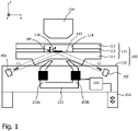
- Figure 1 schematically shows a section through a first embodiment of a (sensor) apparatus 100 that applies the aforementioned technology and is further designed according to the present invention.
- the apparatus 100 comprises (a) a reader 150 with an accommodation space for an exchangeable cartridge 110 and (b) said cartridge 110.
- the apparatus 100 is used for the detection of target components comprised in a sample fluid (e.g. blood) that fills a processing chamber 114 of the cartridge.
- the cartridge 110 is composed of a transparent base part 111 which borders the processing chamber 114 at its bottom side and which provides a processing surface 115.
- the side walls of the processing chamber 114 are constituted by an intermediate layer 112, for example a tape into which openings for the processing chamber and associated fluidic channels (not shown) have been cut.
- the processing chamber 114 is covered at its top side by a (e.g. plastic) cover 113.
- At least one binding region 116 is located on the processing surface 115. It comprises capture probes, for example antibodies, to which certain substances can specifically bind. These substances may particularly be magnetic particles MP with probes (antibodies) on their surface that have (specifically) captured target components of interest from the sample medium in the processing chamber 114.
- Figure 1 further shows a magnetic field generator, here comprising a horse-shoe magnet 153 (with two poles 153a, 153b) below the binding region 116 and a top magnet 154 above it.
- the poles of these magnets may individually be controlled by a control unit 155 of the reader 150 for generating a magnetic field B in the processing chamber 114 by which the magnetic particles MP can be manipulated.
- Figure 1 further indicates a light source 151 for emitting an input light beam L1 into the cartridge 110.
- This input light beam is totally internally reflected at the binding region 116 and then leaves the cartridge 110 as an output light beam L2 towards a light detector 152.
- These light beams can be used to detect target components of the sample fluid that are specifically bound to magnetic particles MP and the capture probes of the binding region 116. Further details of this assay and the optical detection of target components by frustrated total internal reflection (FTIR) may be found for example in the WO 2008/115723 A1 , which is incorporated into the present text by reference.
- FTIR frustrated total internal reflection
- the amount of probes (antibodies) to capture the target molecules needs to be high and as a consequence the amount of magnetic particles in the bulk needs to be high. This causes several problems:
- the cartridge also can be tilted or even turned upside down to allow sedimentation of the unbound beads from the functionalized surface.
- the unbound beads will form only chains with other unbound beads, thus removing all the unbound beads from the beads bound to the surface. This will be explained in more detail in the following.
- Bound magnetic particles MP' and free magnetic particles MP are present in close proximity because the binding process uses a magnetic force to keep all the particles near the binding region 116.
- a magnetic washing field H is switched on to move the free particles away from the surface.
- actually magnetic clustering occurs: due to the magnetic interactions between the magnetic particles, a large number of free beads will couple magnetically to the particles bound to the surface. Therefore these free beads cannot be removed.
- the presence of these free beads near the bound beads distorts the (optical) signal of the bound beads (e.g. the intensity of the bound bead is altered).
- Figure 3 illustrates how this problem can be solved by shortly using a gravitational force.
- Figure 3a corresponds to the starting situation of Figure 2a ).
- gravitational force F g is used directly after the binding process to move the free magnetic particles MP away from the bound magnetic particles MP' of the binding region 116 without having an interaction force between them.
- the magnetic washing force F m can be used to move the free beads further away from the surface. This is shown in Figure 3c ).
- the magnetic interaction force F m decreases with the 4th power of the distance between the particles.
- the surface contains only bound particles without free particles attached to them. The (optical) signal is then a better representation for the number of bound beads on the surface.
- an improvement may be achieved by first switching on an intermediate magnetic field shortly. This will form chains of magnetic beads, particularly of unbound beads to bound beads. Then the gravitational force is allowed to do its work. Due to the (vertical) alignment of the chains and the hydrodynamic coupling between them, they will 'fall' faster than isolated magnetic beads. Finally the magnetic field is switched on again to attract the beads away from the binding region.
- the gravitational force can also be used to remove free, unbound magnetic particles from the printed spot (binding region 116) by means of a sideways translation.
- a component of the gravitational force F g directed along the surface will become available.
- This force component will move free particles MP away from the bound particles MP' in the spot.
- a magnetic force cannot achieve this effect because the magnetic interactions between bound and free particles which will keep the free beads near the bound beads in the spot. This effect is more pronounced when the number of bound beads in the spot is larger.
- the above principles can be realized with the help of a "tilting unit" 156 that is indicated in the Figure as one foot of the apparatus 100 which can be varied in height, controlled by the control unit 155. Accordingly, the whole apparatus 100 with the binding region 115 can be tilted with respect to gravity (z-direction).
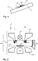
- FIG. 5 schematically shows a side view of a sensor apparatus 200 according to a second embodiment of the present invention.
- the sensor apparatus 200 comprises a reader 250 and an exchangeable cartridge 210.
- the cartridge 210 has a processing chamber 214, filled with a fluid comprising magnetic particles MP, and a binding region 216.
- a tilting unit 256 is symbolically indicated with which the cartridge 210 can controllably be tilted with respect to the reader 250.
- the reader 250 comprises a bottom magnet 253 and a top magnet 254 ("washing magnet”), which now both are horse-shoe magnets.
- This configuration offers the opportunity for a light source 251 directly above the binding region 216 while moving the magnetic beads MP away from the light path.
- a bright field illumination of the binding region 216 is achieved which can be used with a high NA objective lens 252 directly below the binding zone (cf. WO 2011/036634A1 ).
- Removal of unbound magnetic particles can additionally be done by the available electromagnets, using the top magnet 154 (washing magnet) in combination with one of the pole tips 153a, 153b of the bottom magnet (horse-shoe magnet 153) to create an off-center magnetic field direction pulling the beads from the processing chamber 114. It is also possible to bring the beads back to the reaction area by either using only the top magnet or by the combination of both the bottom and top magnet.
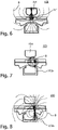
- Figures 6-8 illustrate a preferred procedure of generating and applying magnetic fields in the processing chamber 114. This procedure starts after the usual magnetic actuation (designed to have the optimal specific binding of superparamagnetic beads to the surface) and an intermediate step of particles separation by gravitational forces.
- the unbound beads are pulled away from the field of view by first pulling them to the top of the processing chamber 114 by the top (wash) magnet 154, which removes them from the processing surface but not from the bulk above the surface.
- the beads can then be moved to the side of the processing chamber by using both the top magnet 154 and one of the pole tips 153b of the horse-shoe magnet.
- the use of the top magnet may force the small amount of free beads to form chains on top of the already bound beads making them invisible for detection.
- the beads can then be pulled to the side of the chamber, by using only one of the pole tips 153b of the horse-shoe magnet. Only due to the creation of magnetic fields that are almost parallel to the surface the unbound beads will form chains with the bound beads that are also in parallel to the surface hampering the detection.
- the invention relates to an apparatus and a method for the processing of magnetic particles provided in a processing chamber with a binding region to which said magnetic particles can (specifically) bind. Removal of unbound magnetic particles from the binding region is achieved by first separating them from the binding region by gravitational forces and then moving them further away by magnetic forces. Gravitational forces are generated by tilting the binding region with a tilting unit.
- the basic idea behind using the gravitational force is to prevent the magnetic attachment of free beads to the bound beads on the surface. Generally when the washing magnet is switched on, bound and free beads are magnetized and the free beads will magnetically couple to the bound beads. The gravitational force allows the free beads to move away from the bound beads and thus prevents that unbound magnetic particles are captured in a cluster with bound magnetic particles.
Description
- The invention relates to a method and an apparatus for the processing of magnetic particles that can bind to a binding region.
- The
WO 2010/134005 A1 andWO 2009/016533 A2 disclose an optical biosensor in which frustrated total internal reflection (FTIR) of a light beam is detected and evaluated with respect to the amount of magnetic particles at a binding region. Magnetic fields are used to attract the magnetic particles to said surface for an accelerated binding and to wash unbound magnetic particles away before a detection is made.WO 2007/129275 A2 discloses a method for optical detection of bound magnetic particles. The binding region is either on the vertical wall and the magnetic field is switched off such that the unbound magnetic particles fall down, or it has a fix inclination such that unbound magnetic particles roll down the wall and are pulled further away from the binding region via a magnetic force.US5445971 A discloses an apparatus for the processing of magnetic particles comprising a processing chamber with a binding region, a magnetic field generator for generating a magnetic field in the processing chamber and a tilting means for separating unbound and bound magnetic particles.US2005/0271550 A1 discloses a device for washing magnetic particles in a vessel, the device comprises a holder comprising a lumen for receiving the vessel, wherein the holder comprises a straight side and a sloped side opposite the straight side. The sloped side comprises a lever arm, wherein the lever arm is reciprocally moveable from a position within the holder lumen to a position outside of the holder lumen and the lever arm is biased towards the holder lumen to retain the vessel in the holder lumen. At the entrance a magnet is arranged such that when the vessel is inserted into the holder the magnetic particles are pulled on and along one side wall of the vessel out of the liquid in the vessel when the vessel is fully inserted. During this action the vessel is tilted by the lever arm. - It is an object of the invention to provide means that allow for the processing of magnetic particles at a binding region with improved accuracy.
- This object is achieved by an apparatus according to
claim 1, a method according to claim 2, and a use according to claim 14. - Preferred embodiments are disclosed in the dependent claims.
- The apparatus for the processing of magnetic particles which comprises the following components:
- A chamber that is called "processing chamber" in the following and that comprises a binding region to which magnetic particles can bind. Additionally or alternatively, the apparatus may comprise an accommodation space in which such a reaction chamber can be accommodated. The reaction chamber may then for example be a part of an exchangeable cartridge.
- A magnetic field generator for generating a magnetic field in the processing chamber. The magnetic field generator may for example comprise one or more permanent magnets and/or electromagnets.
- At tilting unit for controllably changing the inclination of the processing chamber or the accommodation space thereby changing the inclination of the binding region, i.e. its orientation with respect to the direction of gravity.
- A control unit for coordinating the inclination and for the generation of the magnetic field.
- The "processing" that can be done with the described apparatus may comprise any kind of e.g. physical or chemical manipulation. In particular, the "processing" may include a detection procedure with which magnetic particles or target components bound thereto are qualitatively or quantitatively detected.
- The term "magnetic particles" shall comprise both permanently magnetic particles as well as magnetizable particles, for example superparamagnetic beads. The size of the magnetic particles typically ranges between 3 nm and 50 µm. Moreover, the magnetic particles may comprise bound target components one is actually interested in. The magnetic particles are usually provided to the processing chamber in some carrier or medium, for example a sample fluid.
- The "processing chamber" is typically an empty cavity or a cavity filled with some substance like a gel that may absorb a sample substance; it may be an open cavity, a closed cavity, or a cavity connected to other cavities by fluid connection channels.
- The "binding region" may extend over the whole surface of the processing chamber, though it will typically be only a part thereof (e.g. lying in the surface of one wall of the processing chamber). The interaction of magnetic particles to the binding region may be of any type, most preferably an intermolecular binding. Moreover, the binding is preferably "specific" in that only particular ones of the magnetic particles present in the processing chamber are able to bind to the binding region. The magnetic particles may for example be provided with capture sites for target components of a sample fluid, wherein only magnetic particles with captured target components are able to bind to the binding region. In this case, bound magnetic particles are an indicator for the presence of the target components of interest.
- The method for the processing of magnetic particles may particularly be executed with an apparatus of the kind described above, and it comprises the following steps:
- a) Providing magnetic particles in a processing chamber that has a binding region.
- b) Letting magnetic particles bind on the binding region.
- c) Separating unbound magnetic particles, which have not bound to the binding region in the previous step, from the binding region by gravitational forces, comprising controllably changing the inclination of the binding region.
- d) Generating with a magnetic field generator a magnetic field which moves the aforementioned unbound magnetic particles that have been separated from the binding region further away from the binding region (i.e. their distance to the binding region is further increased).
- Step b) of letting the magnetic particles bind to the binding region is usually a passive step, requiring mainly that the magnetic particles are given sufficient time to migrate to the binding region and to bind thereto (e.g. driven by chemical affinity). Optionally, this step b) may be actively assisted, for example by attracting magnetic particles magnetically to the binding region in order to accelerate the migration process.
- The separation of unbound magnetic particles in step c) shall particularly comprise that the distance between magnetic particles and the binding region is increased for magnetic particles that are initially close to or even in contact to the binding region. Moreover, the gravitational force is preferably the only (or at least the dominating) external force acting on the magnetic particles during this step. It may for example amount to more than 50 %, preferably more than 90 % of the mean external forces acting on a magnetic particle during the separation step c). Other external forces (of minor influence) which may act on the magnetic particles are hydrodynamic forces (conveyed by the flow of the surrounding medium) and magnetic forces (which are preferably minimized during this step). It should be noted that thermal forces (conveyed by thermal motion of surrounding particles) are considered in this context as "internal forces" and not included in the comparison with gravitational forces.
- The gravitational forces used in the separation step c) have their origin in earth's gravity. Pulling unbound magnetic particles away from the binding region may then be achieved by tilting the binding region, i.e. by giving it an inclination other than horizontal. As an extreme case, the binding region may be turned upside down such that the (unbound) magnetic particles are below the binding region.
- The apparatus and the method according to the invention allow for an improved accuracy of procedures carried out with magnetic particles bound to a binding region. This is because unbound magnetic particles, which could disturb such a procedure, are first separated from the binding region very efficiently by gravitational forces (and then further separated by magnetic forces). The prior use of gravitational forces has the advantage that unbound magnetic particles do not adhere to bound magnetic particles, as is often the case if only magnetic forces are used for the separation. In the latter case, unbound magnetic particles may form clusters (chains) with bound magnetic particles which prevents their separation from the binding region.
- In the following, various preferred embodiments of the invention will be described that relate to the apparatus as well as to the method described above.
- The apparatus comprises a control unit which is designed for coordinating the inclination of the binding region with the generation of the magnetic field(s). This coordination may preferably take place according to the method defined above. In particular, the binding region may be inclined (deviating from horizontal) for a time sufficient to remove unbound magnetic particles from it by a predetermined distance, and thereafter a magnetic field may be generated that continues the separation of the magnetic particles from the binding region. The control unit may for example be realized in dedicated electronic hardware and/or digital data processing hardware with associated software.
- In a preferred embodiment of the invention, the binding region can assume a horizontal orientation below the magnetic particles, i.e. at the bottom of the processing chamber. The horizontal orientation may particularly be assumed during the phase in which magnetic particles bind to the binding region. In this embodiment, gravity tends to move magnetic particles from the interior of the processing chamber towards the binding region (at the binding region itself, the effect of the gravitational forces is counterbalanced by the contact force to the binding region).
- The apparatus may be a one-piece element in which all components are permanently attached to each other. Tilting of the binding region will in this case usually comprise the tilting of the whole apparatus. In a preferred embodiment, the processing chamber with the binding region is located in an exchangeable cartridge which can be introduced into some processing device, wherein cartridge and processing device together constitute an apparatus according to the invention. Such a processing device (without cartridge) is therefore also considered to fall under the scope of the present invention. The cartridge will typically be a disposable component that is used only once for the processing of a medium at hand, for example a sample fluid like blood, saliva, or urine.
- In a further preferred embodiment of the invention, the binding region can be tilted with respect to the magnetic field generator (and/or with respect to other components of the apparatus). This embodiment is particularly possible if the binding region is located in a separate cartridge because tilting of the binding region can then be achieved by tilting (only) said cartridge.
- The time during which gravitational forces act on unbound magnetic particles (at the binding region) is preferably sufficient to move said particles a distance away from bound magnetic particles that is larger than about two times the (mean) diameter of the magnetic particles, preferably larger than three or larger than five times said diameter. Investigations show that unbound magnetic particles which are at least these distances away from bound ones do not form clusters or chains with bound magnetic particles (and hence do not return to the binding region) when the magnetic field is applied that shall move unbound magnetic particles further away from the binding region.
- According to another embodiment of the invention, a further magnetic field (called "intermediate magnetic field" in the following) is generated before the separation of unbound magnetic particles from the binding region by gravitational forces. This "intermediate magnetic field" is intended to induce the formation of chains of magnetic particles, and it is therefore applied only for a comparable short duration that suffices to achieve this (e.g. a few seconds). The chains of magnetic particles, which persist for some time after the intermediate magnetic field has been switched off, are able to move faster through the surrounding medium during the action of gravitational forces. In order to assist this effect, the magnetic field lines of the intermediate magnetic field are preferably oriented parallel to the (later) gravitational forces (i.e. usually vertical).
- Preferably, the unbound magnetic particles are moved to a location outside the binding region, particularly a region where they do not affect the processing at the binding region and in the adjacent volume of the processing chamber. This movement may be achieved by an appropriate magnetic field (acting after the gravitational forces). The location outside the binding region may be such that the part of the processing chamber above the binding region is (approximately) free of unbound magnetic particles, thus allowing for example the transmission of light through this volume without disturbances by unbound magnetic particles.
- In a preferred embodiment of the invention, the magnetic field generator comprises a horse-shoe magnet with (at least) two poles that are located at the binding region, i.e. at a position sufficiently close to the binding region to allow for the generation of magnetic fields at said region and in the adjacent volume of the processing chamber.
- Preferably, at least one of aforementioned poles of the horse-shoe magnet can be activated separately. When the poles of the horse-shoe magnet are arranged symmetrically with respect to the binding region (or the processing chamber), activation of a single pole will usually generate a magnetic field that is asymmetric with respect to the binding region. Such a field can for example be used to move (unbound) magnetic particles to a location outside the binding region.
- In a further embodiment of the invention, the magnetic field generator comprises (additionally or alternatively) magnets that are disposed on opposite sides of the binding region (and hence usually also on opposite sides of the processing chamber). Activating these magnets separately in an appropriate manner can be used to pull unbound magnetic particles away from the binding region.
- The processing of the magnetic particles in the processing chamber may particularly include a processing by optical means. To this end, the apparatus may comprise a light source for illuminating the binding region. The illumination may for example be direct, particularly through the processing chamber and the medium therein. To avoid disturbances of the illumination of the binding region in this case, it is usually important that the medium traversed by the illumination is free of (unbound) magnetic particles. The illumination of the binding region may also be achieved by evanescent waves, generated for example by total internal reflection of an illuminating light beam emitted by the light source.
- The apparatus may optionally comprise a light detector for detecting light coming from the binding region. This light may for example be the aforementioned totally internally reflected light of the light source, wherein a reduction in intensity is an indication of bound magnetic particles at the binding region. This approach is known as "frustrated total internal reflection" (FTIR) and described in more detail in the
WO 2008/155716 A1 ,WO 2009/016533A2 , orWO 2008/072156 A2 . In another example, the detected light may be light of fluorescence that is stimulated in the binding region. - The invention further relates to the use of the apparatus described above for molecular diagnostics, biological sample analysis, chemical sample analysis, food analysis, and/or forensic analysis. Molecular diagnostics may for example be accomplished with the help of magnetic beads or fluorescent particles that are directly or indirectly attached to target molecules.
- These and other aspects of the invention will be apparent from and elucidated with reference to the embodiments described hereinafter.
- In the drawings:
-
Fig. 1 schematically shows a side view of an apparatus according to the present invention comprising an FTIR detection at the binding region; -
Fig. 2 illustrates the effect of a magnetic field acting on bound and unbound magnetic particles at an overhead binding region when gravitational forces act only for a short time; -
Fig. 3 shows the situation ofFigure 2 when gravitational forces act for a longer time; -
Fig. 4 illustrates the effect of gravitational forces on magnetic particles at an inclined binding region; -
Fig. 5 schematically shows a side view of an apparatus according to the present invention comprising a bright-field illumination of the binding region; -
Fig. 6 illustrates the apparatus ofFigure 1 when the magnetic field is generated by the top magnet only; -
Fig. 7 illustrates the apparatus ofFigure 1 when the magnetic field is generated by the top magnet and one pole of the bottom horse-shoe magnet; -
Fig. 8 illustrates the apparatus ofFigure 1 when the magnetic field is generated by one pole of the bottom horse-shoe magnet only. - Like reference numbers or numbers differing by integer multiples of 100 refer in the Figures to identical or similar components.
- Platforms for the specific detection of marker molecules in bodily fluids are for example provided by the Magnotech® technology developed by the applicant. An example of a marker molecule is troponin-I (cTnI) for the detection of cardio-vascular disease. The detection technique is based on immuno-assays in combination with the optical detection of superparamagnetic nanoparticles (beads) on the surface of a cartridge. Many platforms use Total Internal Reflection (TIR) illumination by creating an evanescent optical field near the surface. This technique is surface sensitive and in principle free of interference from the nanoparticles in the bulk.
-
Figure 1 schematically shows a section through a first embodiment of a (sensor)apparatus 100 that applies the aforementioned technology and is further designed according to the present invention. Theapparatus 100 comprises (a) areader 150 with an accommodation space for anexchangeable cartridge 110 and (b) saidcartridge 110. - The
apparatus 100 is used for the detection of target components comprised in a sample fluid (e.g. blood) that fills aprocessing chamber 114 of the cartridge. Thecartridge 110 is composed of atransparent base part 111 which borders theprocessing chamber 114 at its bottom side and which provides aprocessing surface 115. The side walls of theprocessing chamber 114 are constituted by anintermediate layer 112, for example a tape into which openings for the processing chamber and associated fluidic channels (not shown) have been cut. Theprocessing chamber 114 is covered at its top side by a (e.g. plastic)cover 113. - At least one
binding region 116 is located on theprocessing surface 115. It comprises capture probes, for example antibodies, to which certain substances can specifically bind. These substances may particularly be magnetic particles MP with probes (antibodies) on their surface that have (specifically) captured target components of interest from the sample medium in theprocessing chamber 114. -
Figure 1 further shows a magnetic field generator, here comprising a horse-shoe magnet 153 (with twopoles binding region 116 and atop magnet 154 above it. The poles of these magnets may individually be controlled by acontrol unit 155 of thereader 150 for generating a magnetic field B in theprocessing chamber 114 by which the magnetic particles MP can be manipulated. -
Figure 1 further indicates alight source 151 for emitting an input light beam L1 into thecartridge 110. This input light beam is totally internally reflected at thebinding region 116 and then leaves thecartridge 110 as an output light beam L2 towards alight detector 152. These light beams can be used to detect target components of the sample fluid that are specifically bound to magnetic particles MP and the capture probes of thebinding region 116. Further details of this assay and the optical detection of target components by frustrated total internal reflection (FTIR) may be found for example in theWO 2008/115723 A1 , which is incorporated into the present text by reference. - In order to create a fast reaction, the amount of probes (antibodies) to capture the target molecules (e.g. a cardiac marker) needs to be high and as a consequence the amount of magnetic particles in the bulk needs to be high. This causes several problems:
- (a) Due to incorrect alignment of the cartridge and scattering at impurities in the cartridge material itself (e.g. tiny air bubbles, scratches), a fraction of the incoming light may be scattered into the volume of the cartridge instead of being confined near the surface. This causes bulk illumination. Because of scattering at the large amount of magnetic particles in the bulk (the 'bead cloud'), also light from the bulk is therefore detected. This raises the background level and decreases the contrast of the image. Due to the non-uniform distribution of the bead cloud, the background will also be non-uniform.
- (b) The evanescent illumination field decays exponentially with the distance to the surface. Typically the decay length is of the order of 100 nm. The exponential decay causes the intensity of the magnetic particles on the surface to be very sensitive to the height above the surface. Although the height-dependent intensity can give useful information (e.g. about the bond length), it also causes that only a fraction of the magnetic particles on the surface can be detected. By using bright-field illumination from the top of the cartridge as an additional means instead of TIR illumination, the height dependence can be eliminated. However due to the large amount of free nanoparticles, the bright-field illumination is hampered.
- (c) During the magnetic washing (i.e. a magnetic field removes unbound particles from the surface), vertical clusters of magnetic particles are attached to bound magnetic particles. Information about the length of these vertical clusters can improve the performance of the detection. However due to the short decay length of the evanescent field, the size of these vertical clusters is not visible. By using bright field illumination (e.g. in combination with a varying focus depth of the objective lens), an estimate of the vertical cluster size can be obtained. However due to the large amount of free magnetic particles, the bright-field illumination is hampered.
- In order to address the above problems, it is proposed to remove the unbound beads (magnetic particles) after or possibly during the reaction from the processing chamber. Due to the nature of the superparamagnetic beads they will form chains when an external magnetic field is applied. This can hamper the removal of all the unbound magnetic beads from the field of view because a fraction of them will be magnetically coupled to the bound beads on the binding region. One solution is to still remove the large excess of beads leaving only a small part still bound to the surface bound beads. When applying a magnetic field perpendicular to the surface the beads will form chains in the same orientation allowing an easy detection.
- The cartridge also can be tilted or even turned upside down to allow sedimentation of the unbound beads from the functionalized surface. When thereafter the magnetic fields are applied the unbound beads will form only chains with other unbound beads, thus removing all the unbound beads from the beads bound to the surface. This will be explained in more detail in the following.
- Experiments have shown that the binding process in a setup which has been put upside down can be done equally well when the actuation protocol is slightly adapted. The advantage of using the setup upside down is that the gravitational force can improve the washing process.
- This is illustrated in
Figure 2a ), which sketches the situation directly after the binding process. Bound magnetic particles MP' and free magnetic particles MP are present in close proximity because the binding process uses a magnetic force to keep all the particles near thebinding region 116. - In
Figure 2b ), a magnetic washing field H is switched on to move the free particles away from the surface. However, actually magnetic clustering occurs: due to the magnetic interactions between the magnetic particles, a large number of free beads will couple magnetically to the particles bound to the surface. Therefore these free beads cannot be removed. The presence of these free beads near the bound beads distorts the (optical) signal of the bound beads (e.g. the intensity of the bound bead is altered). -
Figure 3 illustrates how this problem can be solved by shortly using a gravitational force.Figure 3a ) corresponds to the starting situation ofFigure 2a ). - According to
Figure 3b ), gravitational force Fg is used directly after the binding process to move the free magnetic particles MP away from the bound magnetic particles MP' of thebinding region 116 without having an interaction force between them. - Once the free magnetic particles have moved some distance Δ from the bound particles (typically a distance of 5-10 µm is sufficient), the magnetic washing force Fm can be used to move the free beads further away from the surface. This is shown in
Figure 3c ). - Because the distance Δ between the bound beads and the free beads is large enough, the magnetic interaction becomes negligible (the magnetic interaction force Fm decreases with the 4th power of the distance between the particles). The surface contains only bound particles without free particles attached to them. The (optical) signal is then a better representation for the number of bound beads on the surface.
- Typically one needs approximately a distance Δ between the bound and the free beads of approximately 5 times the bead diameter d, i.e. Δ ≥ 5d. Then the magnetic attraction force between the beads is low enough to prevent magnetic coupling.
- Some numerical examples are as follows:
For beads with a diameter of d = 500 nm, sedimentation velocity is about 100 nm/s. The distance Δ to travel is then 5·500 nm = 2500 nm. The time the gravitational force has to work is therefore 2500 nm / (100 nm/s) = 25 s. - For d = 1000 nm beads, a velocity of 400 nm/s, the distance to travel is Δ = 5000 nm, with a required time of 5000/400 s = 12.5 s.
- So the time frame depends on the bead diameter and of course the density of the bead (in the above calculation a typical density of 1.8 g/cm3 was used).
- When using gravity to remove unbound magnetic beads from the binding region, an improvement may be achieved by first switching on an intermediate magnetic field shortly. This will form chains of magnetic beads, particularly of unbound beads to bound beads. Then the gravitational force is allowed to do its work. Due to the (vertical) alignment of the chains and the hydrodynamic coupling between them, they will 'fall' faster than isolated magnetic beads. Finally the magnetic field is switched on again to attract the beads away from the binding region.
- With the setup in the normal position, i.e. the
processing surface 115 and thebinding region 116 being oriented horizontally below theprocessing chamber 114, the gravitational force can also be used to remove free, unbound magnetic particles from the printed spot (binding region 116) by means of a sideways translation. This is illustrated inFigure 4 . By tilting thesurface 115, a component of the gravitational force Fg directed along the surface will become available. This force component will move free particles MP away from the bound particles MP' in the spot. Similar toFigure 2 a magnetic force cannot achieve this effect because the magnetic interactions between bound and free particles which will keep the free beads near the bound beads in the spot. This effect is more pronounced when the number of bound beads in the spot is larger. - In the
apparatus 100 ofFigure 1 , the above principles can be realized with the help of a "tilting unit" 156 that is indicated in the Figure as one foot of theapparatus 100 which can be varied in height, controlled by thecontrol unit 155. Accordingly, thewhole apparatus 100 with thebinding region 115 can be tilted with respect to gravity (z-direction). -
Figure 5 schematically shows a side view of asensor apparatus 200 according to a second embodiment of the present invention. Thesensor apparatus 200 comprises areader 250 and anexchangeable cartridge 210. Thecartridge 210 has aprocessing chamber 214, filled with a fluid comprising magnetic particles MP, and abinding region 216. Moreover, atilting unit 256 is symbolically indicated with which thecartridge 210 can controllably be tilted with respect to thereader 250. - The
reader 250 comprises abottom magnet 253 and a top magnet 254 ("washing magnet"), which now both are horse-shoe magnets. This configuration offers the opportunity for alight source 251 directly above thebinding region 216 while moving the magnetic beads MP away from the light path. Thus a bright field illumination of thebinding region 216 is achieved which can be used with a high NAobjective lens 252 directly below the binding zone (cf.WO 2011/036634A1 ). - In summary, the above approach is characterized by the following features:
- 1. Having the binding region with the antibodies in an orientation such that gravity directs particles substantially away from the region.
- 2. "Applying gravity" (no magnetic force) for a sufficiently long time for the magnetic particles to travel more than several bead diameters d from the region.
- 3. Applying a magnetic force directing the particles substantially away from the detection area (defined as the area where the particles still interfere with the detected signal, e.g. by scattering).
- Removal of unbound magnetic particles can additionally be done by the available electromagnets, using the top magnet 154 (washing magnet) in combination with one of the
pole tips processing chamber 114. It is also possible to bring the beads back to the reaction area by either using only the top magnet or by the combination of both the bottom and top magnet. -
Figures 6-8 illustrate a preferred procedure of generating and applying magnetic fields in theprocessing chamber 114. This procedure starts after the usual magnetic actuation (designed to have the optimal specific binding of superparamagnetic beads to the surface) and an intermediate step of particles separation by gravitational forces. - According to
Figure 6 , the unbound beads are pulled away from the field of view by first pulling them to the top of theprocessing chamber 114 by the top (wash)magnet 154, which removes them from the processing surface but not from the bulk above the surface. - According to
Figure 7 , the beads can then be moved to the side of the processing chamber by using both thetop magnet 154 and one of thepole tips 153b of the horse-shoe magnet. In addition the use of the top magnet may force the small amount of free beads to form chains on top of the already bound beads making them invisible for detection. - According to
Figure 8 , the beads can then be pulled to the side of the chamber, by using only one of thepole tips 153b of the horse-shoe magnet. Only due to the creation of magnetic fields that are almost parallel to the surface the unbound beads will form chains with the bound beads that are also in parallel to the surface hampering the detection. - Optionally, one can alternate between one of the pole tips of the horse-
shoe magnet 153 and thetop magnet 154 to ensure that the beads are removed from the field of view. - In summary, the invention relates to an apparatus and a method for the processing of magnetic particles provided in a processing chamber with a binding region to which said magnetic particles can (specifically) bind. Removal of unbound magnetic particles from the binding region is achieved by first separating them from the binding region by gravitational forces and then moving them further away by magnetic forces. Gravitational forces are generated by tilting the binding region with a tilting unit.
- The basic idea behind using the gravitational force is to prevent the magnetic attachment of free beads to the bound beads on the surface. Generally when the washing magnet is switched on, bound and free beads are magnetized and the free beads will magnetically couple to the bound beads. The gravitational force allows the free beads to move away from the bound beads and thus prevents that unbound magnetic particles are captured in a cluster with bound magnetic particles.
- While the invention has been illustrated and described in detail in the drawings and foregoing description, such illustration and description are to be considered illustrative or exemplary and not restrictive; the invention is not limited to the disclosed embodiments. Other variations to the disclosed embodiments can be understood and effected by those skilled in the art in practicing the claimed invention, from a study of the drawings, the disclosure, and the appended claims. In the claims, the word "comprising" does not exclude other elements or steps, and the indefinite article "a" or "an" does not exclude a plurality. The mere fact that certain measures are recited in mutually different dependent claims does not indicate that a combination of these measures cannot be used to advantage. Any reference signs in the claims should not be construed as limiting the scope.
Claims (14)
- An apparatus (100, 200) for processing of magnetic particles (MP, MP'), comprising:- a processing chamber (114, 214) with a binding region (116, 216) to which magnetic particles (MP') can bind or an accommodation space for such a processing chamber;- a magnetic field generator (153, 154, 253, 254) for generating a magnetic field (H) in the processing chamber (114, 214);- a tilting unit (156, 256) for controllably changing the inclination of the processing chamber or the accommodation space thereby changing the inclination of the bindingregion (116, 216), wherein a control unit (155) is provided for coordinating the inclination of the binding region (116, 216) and the generation of the magnetic field (H) such that unbound magnetic particles (MP) separate from the binding region (116, 216) by gravitational forces (Fg) and the magnetic field (H) moves said separated magnetic particles (MP) further away from the binding region (116, 216).
- A method for the processing of magnetic particles (MP, MP'), said method comprising the following steps:- providing magnetic particles (MP, MP') in a processing chamber (114, 214) that has binding region (116, 216);- letting magnetic particles (MP') bind to the binding region (116, 216);- separating unbound magnetic particles (MP) from the binding region (116, 216) by gravitational forces (Fg) comprising controllably changing the inclination of the binding region (116, 216);- generating with a magnetic field generator (153, 154, 253, 254) a magnetic field (H) which moves said separated unbound magnetic particles (MP) further away from the binding region (116, 216).
- The apparatus (100, 200) according to claim 1 or the method according to claim 2,
characterized in that the binding region (116, 216) can assume a horizontal orientation below magnetic particles (MP, MP') present in the processing chamber of said apparatus, particularly while magnetic particles (MP, MP') bind to it. - The apparatus (100, 200) according to claim 1 or the method according to claim 2,
characterized in that the processing chamber (114, 214) with the binding region (116, 216) is located in an exchangeable cartridge (110, 210). - The apparatus (200) according to claim 1 or the method according to claim 2,
characterized in that the binding region (216) can be tilted with respect to the magnetic field generator (253, 254). - The method according to claim 2,
characterized in that the gravitational forces (Fg) act for a time that is sufficient to move unbound magnetic particles (MP) a distance (Δ) of more than about two times their diameter (d) away from magnetic particles (MP') bound to the binding region (116, 216). - The method according to claim 2,
characterized in that an intermediate magnetic field is generated prior to the separation of unbound magnetic particles (MP) from the binding region. - The method according to claim 2,
characterized in that the unbound magnetic particles (MP) are or can be moved to a location outside the binding region (116, 216). - The apparatus (100, 200) according to claim 1 or the method according to claim 2,
characterized in that the magnetic field generator comprises a horse-shoe magnet (153, 253, 254) the poles (153a, 153b) of which are located at the binding region (116,216). - The apparatus (100, 200) or the method according to claim 9,
characterized in that at least one pole (153a, 153b) of the horse-shoe magnet (153, 253, 254) can be activated separately. - The apparatus (100, 200) according to claim 1 or the method according to claim 2,
characterized in that the magnetic field generator comprises magnets (153, 154, 253, 254) disposed on opposite sides of the binding region (116, 216). - The apparatus (100, 200) according to claim 1 or the method according to claim 2,
characterized in that a light source (151, 251) is provided for illuminating the binding region (116, 216). - The apparatus (100, 200) according to claim 1 or the method according to claim 2,
characterized in that a light detector (152, 252) is provided for detecting light (L2) coming from the binding region (116, 216). - Use of the apparatus (100, 200) according to any of the claims 1, 3 to 5, 9 to 11 and 12 for molecular diagnostics, biological sample analysis, chemical sample analysis, food analysis, and/or forensic analysis.
Applications Claiming Priority (2)
| Application Number | Priority Date | Filing Date | Title |
|---|---|---|---|
| US201261665922P | 2012-06-29 | 2012-06-29 | |
| PCT/IB2013/055072 WO2014001982A1 (en) | 2012-06-29 | 2013-06-20 | Processing of bound and unbound magnetic particles |
Publications (2)
| Publication Number | Publication Date |
|---|---|
| EP2867663A1 EP2867663A1 (en) | 2015-05-06 |
| EP2867663B1 true EP2867663B1 (en) | 2022-12-07 |
Family
ID=49162179
Family Applications (1)
| Application Number | Title | Priority Date | Filing Date |
|---|---|---|---|
| EP13760113.4A Active EP2867663B1 (en) | 2012-06-29 | 2013-06-20 | Processing of bound and unbound magnetic particles |
Country Status (7)
| Country | Link |
|---|---|
| US (1) | US10079086B2 (en) |
| EP (1) | EP2867663B1 (en) |
| JP (1) | JP6297546B2 (en) |
| CN (1) | CN104395736B (en) |
| BR (1) | BR112014031983A2 (en) |
| RU (1) | RU2015102829A (en) |
| WO (1) | WO2014001982A1 (en) |
Families Citing this family (7)
| Publication number | Priority date | Publication date | Assignee | Title |
|---|---|---|---|---|
| US9207210B2 (en) * | 2010-09-09 | 2015-12-08 | Koninklijke Philips N.V. | Method and a device for attracting magnetic particles to a surface |
| EP2527814A1 (en) * | 2011-04-27 | 2012-11-28 | Koninklijke Philips Electronics N.V. | Sensor system with an exchangeable cartridge and a reader |
| BR112017019454B1 (en) * | 2015-03-13 | 2023-03-07 | 3M Innovative Properties Company | LIGHT DETECTION DEVICE |
| WO2016148922A1 (en) | 2015-03-13 | 2016-09-22 | 3M Innovative Properties Company | Light detection system and method of using same |
| BR112017018988B1 (en) | 2015-03-13 | 2021-05-04 | 3M Innovative Properties Company | light detection device and light detection system |
| CN106596473A (en) * | 2016-10-27 | 2017-04-26 | 中国科学院电子学研究所 | Optic detector based on electric control magnet enrichment-separation and total internal reflection magnetic imaging |
| EP3470141A1 (en) * | 2017-10-11 | 2019-04-17 | F. Hoffmann-La Roche AG | Method for processing a biological sample with magnetic particles |
Citations (1)
| Publication number | Priority date | Publication date | Assignee | Title |
|---|---|---|---|---|
| US20050271550A1 (en) * | 2004-06-08 | 2005-12-08 | Mark Talmer | Tapered cuvette and method of collecting magnetic particles |
Family Cites Families (34)
| Publication number | Priority date | Publication date | Assignee | Title |
|---|---|---|---|---|
| US3967892A (en) * | 1974-07-26 | 1976-07-06 | Xerox Corporation | Development system |
| US3945343A (en) * | 1975-03-24 | 1976-03-23 | General Electric Company | Magnetic brush for use in magnetic printing |
| JPS5635162A (en) * | 1979-08-31 | 1981-04-07 | Konishiroku Photo Ind Co Ltd | Electrostatic recorder |
| JPS58163961A (en) * | 1982-03-25 | 1983-09-28 | Fujitsu Ltd | Multicolor printing method |
| JPS5923358A (en) * | 1982-07-30 | 1984-02-06 | Toshiba Corp | Developing device |
| GB2145942B (en) * | 1983-08-05 | 1987-03-18 | Konishiroku Photo Ind | Developing latent eletrostatic images |
| CN1034617A (en) * | 1987-10-09 | 1989-08-09 | 奈吉尼股份有限公司 | Identify the method and the device of biochemical species |
| US5047807A (en) * | 1990-10-15 | 1991-09-10 | Eastman Kodak Company | Development apparatus having a plate scavenging device |
| US5184194A (en) * | 1991-10-28 | 1993-02-02 | Eastman Kodak Company | Carrier particle scavenging device |
| US5445971A (en) | 1992-03-20 | 1995-08-29 | Abbott Laboratories | Magnetically assisted binding assays using magnetically labeled binding members |
| ATE195081T1 (en) * | 1992-09-24 | 2000-08-15 | Amersham Pharm Biotech Uk Ltd | METHOD AND DEVICE FOR MAGNETIC DEPOSITION |
| JP4284431B2 (en) * | 1997-12-15 | 2009-06-24 | 株式会社シノテスト | Measuring instrument and measuring method for test substance using particles |
| FR2826882B1 (en) * | 2001-07-09 | 2003-09-12 | Bio Merieux | PROCESS FOR THE TREATMENT OF MAGNETIC PARTICLES AND CONFIGURATIONS OF MAGNETS ALLOWING THE IMPLEMENTATION OF THIS PROCESS |
| DE10136060A1 (en) * | 2001-07-25 | 2003-02-13 | Roche Diagnostics Gmbh | System for the separation of magnetically attractable particles |
| DE60315415T2 (en) * | 2002-01-29 | 2008-04-30 | Asahi Kasei Kabushiki Kaisha | BIOSENSOR, MAGNETIC MOLECULE MEASURING PROCESS AND MEASURING OBJECT MEASUREMENT PROCESS |
| FI120863B (en) * | 2002-10-18 | 2010-04-15 | Biocontrol Systems Inc | Magnetic transfer method and microparticle transfer device |
| US8118044B2 (en) | 2004-03-12 | 2012-02-21 | Applied Materials, Inc. | Single workpiece processing chamber with tilting load/unload upper rim |
| EP2239342A3 (en) | 2005-02-01 | 2010-11-03 | AB Advanced Genetic Analysis Corporation | Reagents, methods and libraries for bead-based sequencing |
| JP2009538123A (en) | 2006-04-19 | 2009-11-05 | アプライド バイオシステムズ, エルエルシー | Reagents, methods and libraries for gel-free bead-based sequencing |
| EP2018537B1 (en) * | 2006-05-10 | 2013-07-17 | Koninklijke Philips Electronics N.V. | Rapid magnetic biosensor |
| JP2009544033A (en) * | 2006-07-17 | 2009-12-10 | コーニンクレッカ フィリップス エレクトロニクス エヌ ヴィ | Attraction and separation of magnetic or magnetizable objects from the sensor surface |
| US9658219B2 (en) | 2006-12-12 | 2017-05-23 | Koninklijke Philips N.V. | Microelectronic sensor device for detecting label particles |
| EP2129371B1 (en) | 2007-03-19 | 2021-05-05 | ATM Metabolics LLLP | Composition for treating diabetes and metabolic disorders with quercetin, myrcetin and chlorogenic acid |
| EP2181322A1 (en) | 2007-06-21 | 2010-05-05 | Koninklijke Philips Electronics N.V. | Microelectronic sensor device for detecting label particles |
| CN101779117B (en) * | 2007-07-31 | 2013-12-04 | 皇家飞利浦电子股份有限公司 | Microelectronic sensor device with a light source |
| JP2010539982A (en) | 2007-10-01 | 2010-12-24 | アプライド バイオシステムズ, エルエルシー | Chase ligation sequencing |
| CA2756463C (en) | 2009-03-24 | 2019-01-22 | University Of Chicago | Slip chip device and methods |
| EP2599548B1 (en) * | 2009-05-13 | 2018-07-04 | ibidi GmbH | Sample holder for positioning an organic, biological and/or medical sample |
| CN102439448A (en) | 2009-05-19 | 2012-05-02 | 皇家飞利浦电子股份有限公司 | Sensor device for magnetic particles with a high dynamic range |
| US9250181B2 (en) * | 2009-09-28 | 2016-02-02 | Koninklijke Philips N.V. | Sensor device with imaging optics |
| WO2011036634A1 (en) | 2009-09-28 | 2011-03-31 | Koninklijke Philips Electronics N.V. | A biosensor system for single particle detection |
| EP2513636B1 (en) * | 2009-12-18 | 2020-08-05 | Koninklijke Philips N.V. | Substance determining apparatus |
| JP5573335B2 (en) * | 2010-04-28 | 2014-08-20 | 株式会社島津製作所 | Magnetic particle manipulation device and magnetic particle manipulation method |
| CN102947703A (en) | 2010-06-17 | 2013-02-27 | 皇家飞利浦电子股份有限公司 | Multi epitope assay |
-
2013
- 2013-06-20 RU RU2015102829A patent/RU2015102829A/en unknown
- 2013-06-20 BR BR112014031983A patent/BR112014031983A2/en not_active IP Right Cessation
- 2013-06-20 CN CN201380034882.7A patent/CN104395736B/en active Active
- 2013-06-20 JP JP2015519424A patent/JP6297546B2/en active Active
- 2013-06-20 US US14/409,922 patent/US10079086B2/en active Active
- 2013-06-20 EP EP13760113.4A patent/EP2867663B1/en active Active
- 2013-06-20 WO PCT/IB2013/055072 patent/WO2014001982A1/en active Application Filing
Patent Citations (1)
| Publication number | Priority date | Publication date | Assignee | Title |
|---|---|---|---|---|
| US20050271550A1 (en) * | 2004-06-08 | 2005-12-08 | Mark Talmer | Tapered cuvette and method of collecting magnetic particles |
Also Published As
| Publication number | Publication date |
|---|---|
| JP2015522155A (en) | 2015-08-03 |
| CN104395736A (en) | 2015-03-04 |
| JP6297546B2 (en) | 2018-03-20 |
| US20150187479A1 (en) | 2015-07-02 |
| WO2014001982A1 (en) | 2014-01-03 |
| CN104395736B (en) | 2018-12-11 |
| US10079086B2 (en) | 2018-09-18 |
| RU2015102829A (en) | 2016-08-20 |
| BR112014031983A2 (en) | 2017-06-27 |
| EP2867663A1 (en) | 2015-05-06 |
Similar Documents
| Publication | Publication Date | Title |
|---|---|---|
| EP2867663B1 (en) | Processing of bound and unbound magnetic particles | |
| JP6965272B2 (en) | High throughput particle capture and analysis | |
| US20130088221A1 (en) | Detection of magnetic particles and their clustering | |
| JP6291491B2 (en) | Treatment of fluids containing interference particles | |
| US8283912B2 (en) | Sensor device with magnetic washing means | |
| EP2433129A1 (en) | Sensor device for magnetic particles with a high dynamic range | |
| JP2014531029A (en) | Detection of magnetic particles using culture period | |
| JP6154393B2 (en) | Method and sensor device for detecting magnetic particles | |
| CN109804235B (en) | Target substance detection device and target substance detection method | |
| JP2012515917A (en) | Mixed actuation protocol for magnetic biosensor devices | |
| US10876964B2 (en) | System, apparatus and method for determining a substance within a fluid | |
| JP2017067759A (en) | Detection method and detection device | |
| JP2015125032A (en) | Cleaning apparatus and cleaning method | |
| JP2024509775A (en) | Methods and apparatus for analyzing liquids that may contain analytes | |
| JP2021025844A (en) | Concentration measurement method and concentration measurement device | |
| WO2012101539A1 (en) | Localization of detection spots | |
| JP2017090217A (en) | Test device, test method, and test apparatus |
Legal Events
| Date | Code | Title | Description |
|---|---|---|---|
| PUAI | Public reference made under article 153(3) epc to a published international application that has entered the european phase |
Free format text: ORIGINAL CODE: 0009012 |
|
| 17P | Request for examination filed |
Effective date: 20150129 |
|
| AK | Designated contracting states |
Kind code of ref document: A1 Designated state(s): AL AT BE BG CH CY CZ DE DK EE ES FI FR GB GR HR HU IE IS IT LI LT LU LV MC MK MT NL NO PL PT RO RS SE SI SK SM TR |
|
| AX | Request for extension of the european patent |
Extension state: BA ME |
|
| DAX | Request for extension of the european patent (deleted) | ||
| STAA | Information on the status of an ep patent application or granted ep patent |
Free format text: STATUS: EXAMINATION IS IN PROGRESS |
|
| 17Q | First examination report despatched |
Effective date: 20200129 |
|
| RAP1 | Party data changed (applicant data changed or rights of an application transferred) |
Owner name: KONINKLIJKE PHILIPS N.V. |
|
| STAA | Information on the status of an ep patent application or granted ep patent |
Free format text: STATUS: EXAMINATION IS IN PROGRESS |
|
| REG | Reference to a national code |
Ref country code: DE Ref legal event code: R079 Ref document number: 602013083011 Country of ref document: DE Free format text: PREVIOUS MAIN CLASS: G01N0027740000 Ipc: G01N0021552000 |
|
| GRAP | Despatch of communication of intention to grant a patent |
Free format text: ORIGINAL CODE: EPIDOSNIGR1 |
|
| STAA | Information on the status of an ep patent application or granted ep patent |
Free format text: STATUS: GRANT OF PATENT IS INTENDED |
|
| RIC1 | Information provided on ipc code assigned before grant |
Ipc: G01N 21/552 20140101AFI20220614BHEP |
|
| INTG | Intention to grant announced |
Effective date: 20220704 |
|
| GRAS | Grant fee paid |
Free format text: ORIGINAL CODE: EPIDOSNIGR3 |
|
| GRAA | (expected) grant |
Free format text: ORIGINAL CODE: 0009210 |
|
| STAA | Information on the status of an ep patent application or granted ep patent |
Free format text: STATUS: THE PATENT HAS BEEN GRANTED |
|
| AK | Designated contracting states |
Kind code of ref document: B1 Designated state(s): AL AT BE BG CH CY CZ DE DK EE ES FI FR GB GR HR HU IE IS IT LI LT LU LV MC MK MT NL NO PL PT RO RS SE SI SK SM TR |
|
| REG | Reference to a national code |
Ref country code: GB Ref legal event code: FG4D |
|
| REG | Reference to a national code |
Ref country code: CH Ref legal event code: EP Ref country code: AT Ref legal event code: REF Ref document number: 1536585 Country of ref document: AT Kind code of ref document: T Effective date: 20221215 |
|
| REG | Reference to a national code |
Ref country code: DE Ref legal event code: R096 Ref document number: 602013083011 Country of ref document: DE |
|
| REG | Reference to a national code |
Ref country code: IE Ref legal event code: FG4D |
|
| REG | Reference to a national code |
Ref country code: LT Ref legal event code: MG9D |
|
| REG | Reference to a national code |
Ref country code: NL Ref legal event code: MP Effective date: 20221207 |
|
| PG25 | Lapsed in a contracting state [announced via postgrant information from national office to epo] |
Ref country code: SE Free format text: LAPSE BECAUSE OF FAILURE TO SUBMIT A TRANSLATION OF THE DESCRIPTION OR TO PAY THE FEE WITHIN THE PRESCRIBED TIME-LIMIT Effective date: 20221207 Ref country code: NO Free format text: LAPSE BECAUSE OF FAILURE TO SUBMIT A TRANSLATION OF THE DESCRIPTION OR TO PAY THE FEE WITHIN THE PRESCRIBED TIME-LIMIT Effective date: 20230307 Ref country code: LT Free format text: LAPSE BECAUSE OF FAILURE TO SUBMIT A TRANSLATION OF THE DESCRIPTION OR TO PAY THE FEE WITHIN THE PRESCRIBED TIME-LIMIT Effective date: 20221207 Ref country code: FI Free format text: LAPSE BECAUSE OF FAILURE TO SUBMIT A TRANSLATION OF THE DESCRIPTION OR TO PAY THE FEE WITHIN THE PRESCRIBED TIME-LIMIT Effective date: 20221207 Ref country code: ES Free format text: LAPSE BECAUSE OF FAILURE TO SUBMIT A TRANSLATION OF THE DESCRIPTION OR TO PAY THE FEE WITHIN THE PRESCRIBED TIME-LIMIT Effective date: 20221207 |
|
| REG | Reference to a national code |
Ref country code: AT Ref legal event code: MK05 Ref document number: 1536585 Country of ref document: AT Kind code of ref document: T Effective date: 20221207 |
|
| PG25 | Lapsed in a contracting state [announced via postgrant information from national office to epo] |
Ref country code: RS Free format text: LAPSE BECAUSE OF FAILURE TO SUBMIT A TRANSLATION OF THE DESCRIPTION OR TO PAY THE FEE WITHIN THE PRESCRIBED TIME-LIMIT Effective date: 20221207 Ref country code: PL Free format text: LAPSE BECAUSE OF FAILURE TO SUBMIT A TRANSLATION OF THE DESCRIPTION OR TO PAY THE FEE WITHIN THE PRESCRIBED TIME-LIMIT Effective date: 20221207 Ref country code: LV Free format text: LAPSE BECAUSE OF FAILURE TO SUBMIT A TRANSLATION OF THE DESCRIPTION OR TO PAY THE FEE WITHIN THE PRESCRIBED TIME-LIMIT Effective date: 20221207 Ref country code: HR Free format text: LAPSE BECAUSE OF FAILURE TO SUBMIT A TRANSLATION OF THE DESCRIPTION OR TO PAY THE FEE WITHIN THE PRESCRIBED TIME-LIMIT Effective date: 20221207 Ref country code: GR Free format text: LAPSE BECAUSE OF FAILURE TO SUBMIT A TRANSLATION OF THE DESCRIPTION OR TO PAY THE FEE WITHIN THE PRESCRIBED TIME-LIMIT Effective date: 20230308 |
|
| PG25 | Lapsed in a contracting state [announced via postgrant information from national office to epo] |
Ref country code: NL Free format text: LAPSE BECAUSE OF FAILURE TO SUBMIT A TRANSLATION OF THE DESCRIPTION OR TO PAY THE FEE WITHIN THE PRESCRIBED TIME-LIMIT Effective date: 20221207 |
|
| PG25 | Lapsed in a contracting state [announced via postgrant information from national office to epo] |
Ref country code: SM Free format text: LAPSE BECAUSE OF FAILURE TO SUBMIT A TRANSLATION OF THE DESCRIPTION OR TO PAY THE FEE WITHIN THE PRESCRIBED TIME-LIMIT Effective date: 20221207 Ref country code: RO Free format text: LAPSE BECAUSE OF FAILURE TO SUBMIT A TRANSLATION OF THE DESCRIPTION OR TO PAY THE FEE WITHIN THE PRESCRIBED TIME-LIMIT Effective date: 20221207 Ref country code: PT Free format text: LAPSE BECAUSE OF FAILURE TO SUBMIT A TRANSLATION OF THE DESCRIPTION OR TO PAY THE FEE WITHIN THE PRESCRIBED TIME-LIMIT Effective date: 20230410 Ref country code: EE Free format text: LAPSE BECAUSE OF FAILURE TO SUBMIT A TRANSLATION OF THE DESCRIPTION OR TO PAY THE FEE WITHIN THE PRESCRIBED TIME-LIMIT Effective date: 20221207 Ref country code: CZ Free format text: LAPSE BECAUSE OF FAILURE TO SUBMIT A TRANSLATION OF THE DESCRIPTION OR TO PAY THE FEE WITHIN THE PRESCRIBED TIME-LIMIT Effective date: 20221207 Ref country code: AT Free format text: LAPSE BECAUSE OF FAILURE TO SUBMIT A TRANSLATION OF THE DESCRIPTION OR TO PAY THE FEE WITHIN THE PRESCRIBED TIME-LIMIT Effective date: 20221207 |
|
| PGFP | Annual fee paid to national office [announced via postgrant information from national office to epo] |
Ref country code: FR Payment date: 20230622 Year of fee payment: 11 Ref country code: DE Payment date: 20230627 Year of fee payment: 11 |
|
| PG25 | Lapsed in a contracting state [announced via postgrant information from national office to epo] |
Ref country code: SK Free format text: LAPSE BECAUSE OF FAILURE TO SUBMIT A TRANSLATION OF THE DESCRIPTION OR TO PAY THE FEE WITHIN THE PRESCRIBED TIME-LIMIT Effective date: 20221207 Ref country code: IS Free format text: LAPSE BECAUSE OF FAILURE TO SUBMIT A TRANSLATION OF THE DESCRIPTION OR TO PAY THE FEE WITHIN THE PRESCRIBED TIME-LIMIT Effective date: 20230407 Ref country code: AL Free format text: LAPSE BECAUSE OF FAILURE TO SUBMIT A TRANSLATION OF THE DESCRIPTION OR TO PAY THE FEE WITHIN THE PRESCRIBED TIME-LIMIT Effective date: 20221207 |
|
| REG | Reference to a national code |
Ref country code: DE Ref legal event code: R097 Ref document number: 602013083011 Country of ref document: DE |
|
| PLBE | No opposition filed within time limit |
Free format text: ORIGINAL CODE: 0009261 |
|
| STAA | Information on the status of an ep patent application or granted ep patent |
Free format text: STATUS: NO OPPOSITION FILED WITHIN TIME LIMIT |
|
| PG25 | Lapsed in a contracting state [announced via postgrant information from national office to epo] |
Ref country code: DK Free format text: LAPSE BECAUSE OF FAILURE TO SUBMIT A TRANSLATION OF THE DESCRIPTION OR TO PAY THE FEE WITHIN THE PRESCRIBED TIME-LIMIT Effective date: 20221207 |
|
| PGFP | Annual fee paid to national office [announced via postgrant information from national office to epo] |
Ref country code: GB Payment date: 20230620 Year of fee payment: 11 Ref country code: CH Payment date: 20230702 Year of fee payment: 11 |
|
| 26N | No opposition filed |
Effective date: 20230908 |
|
| PG25 | Lapsed in a contracting state [announced via postgrant information from national office to epo] |
Ref country code: SI Free format text: LAPSE BECAUSE OF FAILURE TO SUBMIT A TRANSLATION OF THE DESCRIPTION OR TO PAY THE FEE WITHIN THE PRESCRIBED TIME-LIMIT Effective date: 20221207 |
|
| PG25 | Lapsed in a contracting state [announced via postgrant information from national office to epo] |
Ref country code: MC Free format text: LAPSE BECAUSE OF FAILURE TO SUBMIT A TRANSLATION OF THE DESCRIPTION OR TO PAY THE FEE WITHIN THE PRESCRIBED TIME-LIMIT Effective date: 20221207 |
|
| PG25 | Lapsed in a contracting state [announced via postgrant information from national office to epo] |
Ref country code: MC Free format text: LAPSE BECAUSE OF FAILURE TO SUBMIT A TRANSLATION OF THE DESCRIPTION OR TO PAY THE FEE WITHIN THE PRESCRIBED TIME-LIMIT Effective date: 20221207 |
|
| REG | Reference to a national code |
Ref country code: BE Ref legal event code: MM Effective date: 20230630 |
|
| PG25 | Lapsed in a contracting state [announced via postgrant information from national office to epo] |
Ref country code: LU Free format text: LAPSE BECAUSE OF NON-PAYMENT OF DUE FEES Effective date: 20230620 |
|
| REG | Reference to a national code |
Ref country code: IE Ref legal event code: MM4A |
|
| PG25 | Lapsed in a contracting state [announced via postgrant information from national office to epo] |
Ref country code: LU Free format text: LAPSE BECAUSE OF NON-PAYMENT OF DUE FEES Effective date: 20230620 |