JP6965272B2 - High throughput particle capture and analysis - Google Patents
High throughput particle capture and analysis Download PDFInfo
- Publication number
- JP6965272B2 JP6965272B2 JP2018555231A JP2018555231A JP6965272B2 JP 6965272 B2 JP6965272 B2 JP 6965272B2 JP 2018555231 A JP2018555231 A JP 2018555231A JP 2018555231 A JP2018555231 A JP 2018555231A JP 6965272 B2 JP6965272 B2 JP 6965272B2
- Authority
- JP
- Japan
- Prior art keywords
- microwell
- array
- microwells
- target entity
- cells
- Prior art date
- Legal status (The legal status is an assumption and is not a legal conclusion. Google has not performed a legal analysis and makes no representation as to the accuracy of the status listed.)
- Active
Links
- 0 *CC1(C(C*=*)*C2)C2(*)C(*)(C*=C*)*CCCCCCCICCCCCCC1 Chemical compound *CC1(C(C*=*)*C2)C2(*)C(*)(C*=C*)*CCCCCCCICCCCCCC1 0.000 description 1
Images


Classifications
-
- B—PERFORMING OPERATIONS; TRANSPORTING
- B01—PHYSICAL OR CHEMICAL PROCESSES OR APPARATUS IN GENERAL
- B01L—CHEMICAL OR PHYSICAL LABORATORY APPARATUS FOR GENERAL USE
- B01L3/00—Containers or dishes for laboratory use, e.g. laboratory glassware; Droppers
- B01L3/50—Containers for the purpose of retaining a material to be analysed, e.g. test tubes
- B01L3/502—Containers for the purpose of retaining a material to be analysed, e.g. test tubes with fluid transport, e.g. in multi-compartment structures
- B01L3/5027—Containers for the purpose of retaining a material to be analysed, e.g. test tubes with fluid transport, e.g. in multi-compartment structures by integrated microfluidic structures, i.e. dimensions of channels and chambers are such that surface tension forces are important, e.g. lab-on-a-chip
- B01L3/502761—Containers for the purpose of retaining a material to be analysed, e.g. test tubes with fluid transport, e.g. in multi-compartment structures by integrated microfluidic structures, i.e. dimensions of channels and chambers are such that surface tension forces are important, e.g. lab-on-a-chip specially adapted for handling suspended solids or molecules independently from the bulk fluid flow, e.g. for trapping or sorting beads, for physically stretching molecules
-
- B—PERFORMING OPERATIONS; TRANSPORTING
- B03—SEPARATION OF SOLID MATERIALS USING LIQUIDS OR USING PNEUMATIC TABLES OR JIGS; MAGNETIC OR ELECTROSTATIC SEPARATION OF SOLID MATERIALS FROM SOLID MATERIALS OR FLUIDS; SEPARATION BY HIGH-VOLTAGE ELECTRIC FIELDS
- B03C—MAGNETIC OR ELECTROSTATIC SEPARATION OF SOLID MATERIALS FROM SOLID MATERIALS OR FLUIDS; SEPARATION BY HIGH-VOLTAGE ELECTRIC FIELDS
- B03C1/00—Magnetic separation
- B03C1/005—Pretreatment specially adapted for magnetic separation
- B03C1/01—Pretreatment specially adapted for magnetic separation by addition of magnetic adjuvants
-
- B—PERFORMING OPERATIONS; TRANSPORTING
- B03—SEPARATION OF SOLID MATERIALS USING LIQUIDS OR USING PNEUMATIC TABLES OR JIGS; MAGNETIC OR ELECTROSTATIC SEPARATION OF SOLID MATERIALS FROM SOLID MATERIALS OR FLUIDS; SEPARATION BY HIGH-VOLTAGE ELECTRIC FIELDS
- B03C—MAGNETIC OR ELECTROSTATIC SEPARATION OF SOLID MATERIALS FROM SOLID MATERIALS OR FLUIDS; SEPARATION BY HIGH-VOLTAGE ELECTRIC FIELDS
- B03C1/00—Magnetic separation
- B03C1/02—Magnetic separation acting directly on the substance being separated
- B03C1/025—High gradient magnetic separators
- B03C1/031—Component parts; Auxiliary operations
- B03C1/033—Component parts; Auxiliary operations characterised by the magnetic circuit
- B03C1/0332—Component parts; Auxiliary operations characterised by the magnetic circuit using permanent magnets
-
- B—PERFORMING OPERATIONS; TRANSPORTING
- B03—SEPARATION OF SOLID MATERIALS USING LIQUIDS OR USING PNEUMATIC TABLES OR JIGS; MAGNETIC OR ELECTROSTATIC SEPARATION OF SOLID MATERIALS FROM SOLID MATERIALS OR FLUIDS; SEPARATION BY HIGH-VOLTAGE ELECTRIC FIELDS
- B03C—MAGNETIC OR ELECTROSTATIC SEPARATION OF SOLID MATERIALS FROM SOLID MATERIALS OR FLUIDS; SEPARATION BY HIGH-VOLTAGE ELECTRIC FIELDS
- B03C1/00—Magnetic separation
- B03C1/02—Magnetic separation acting directly on the substance being separated
- B03C1/025—High gradient magnetic separators
- B03C1/031—Component parts; Auxiliary operations
- B03C1/033—Component parts; Auxiliary operations characterised by the magnetic circuit
- B03C1/0335—Component parts; Auxiliary operations characterised by the magnetic circuit using coils
-
- B—PERFORMING OPERATIONS; TRANSPORTING
- B03—SEPARATION OF SOLID MATERIALS USING LIQUIDS OR USING PNEUMATIC TABLES OR JIGS; MAGNETIC OR ELECTROSTATIC SEPARATION OF SOLID MATERIALS FROM SOLID MATERIALS OR FLUIDS; SEPARATION BY HIGH-VOLTAGE ELECTRIC FIELDS
- B03C—MAGNETIC OR ELECTROSTATIC SEPARATION OF SOLID MATERIALS FROM SOLID MATERIALS OR FLUIDS; SEPARATION BY HIGH-VOLTAGE ELECTRIC FIELDS
- B03C1/00—Magnetic separation
- B03C1/02—Magnetic separation acting directly on the substance being separated
- B03C1/28—Magnetic plugs and dipsticks
- B03C1/288—Magnetic plugs and dipsticks disposed at the outer circumference of a recipient
-
- B—PERFORMING OPERATIONS; TRANSPORTING
- B01—PHYSICAL OR CHEMICAL PROCESSES OR APPARATUS IN GENERAL
- B01L—CHEMICAL OR PHYSICAL LABORATORY APPARATUS FOR GENERAL USE
- B01L2200/00—Solutions for specific problems relating to chemical or physical laboratory apparatus
- B01L2200/06—Fluid handling related problems
- B01L2200/0647—Handling flowable solids, e.g. microscopic beads, cells, particles
- B01L2200/0652—Sorting or classification of particles or molecules
-
- B—PERFORMING OPERATIONS; TRANSPORTING
- B01—PHYSICAL OR CHEMICAL PROCESSES OR APPARATUS IN GENERAL
- B01L—CHEMICAL OR PHYSICAL LABORATORY APPARATUS FOR GENERAL USE
- B01L2200/00—Solutions for specific problems relating to chemical or physical laboratory apparatus
- B01L2200/06—Fluid handling related problems
- B01L2200/0647—Handling flowable solids, e.g. microscopic beads, cells, particles
- B01L2200/0668—Trapping microscopic beads
-
- B—PERFORMING OPERATIONS; TRANSPORTING
- B01—PHYSICAL OR CHEMICAL PROCESSES OR APPARATUS IN GENERAL
- B01L—CHEMICAL OR PHYSICAL LABORATORY APPARATUS FOR GENERAL USE
- B01L2200/00—Solutions for specific problems relating to chemical or physical laboratory apparatus
- B01L2200/06—Fluid handling related problems
- B01L2200/0673—Handling of plugs of fluid surrounded by immiscible fluid
-
- B—PERFORMING OPERATIONS; TRANSPORTING
- B01—PHYSICAL OR CHEMICAL PROCESSES OR APPARATUS IN GENERAL
- B01L—CHEMICAL OR PHYSICAL LABORATORY APPARATUS FOR GENERAL USE
- B01L2200/00—Solutions for specific problems relating to chemical or physical laboratory apparatus
- B01L2200/06—Fluid handling related problems
- B01L2200/0689—Sealing
-
- B—PERFORMING OPERATIONS; TRANSPORTING
- B01—PHYSICAL OR CHEMICAL PROCESSES OR APPARATUS IN GENERAL
- B01L—CHEMICAL OR PHYSICAL LABORATORY APPARATUS FOR GENERAL USE
- B01L2300/00—Additional constructional details
- B01L2300/06—Auxiliary integrated devices, integrated components
- B01L2300/0627—Sensor or part of a sensor is integrated
-
- B—PERFORMING OPERATIONS; TRANSPORTING
- B01—PHYSICAL OR CHEMICAL PROCESSES OR APPARATUS IN GENERAL
- B01L—CHEMICAL OR PHYSICAL LABORATORY APPARATUS FOR GENERAL USE
- B01L2300/00—Additional constructional details
- B01L2300/08—Geometry, shape and general structure
- B01L2300/0803—Disc shape
-
- B—PERFORMING OPERATIONS; TRANSPORTING
- B01—PHYSICAL OR CHEMICAL PROCESSES OR APPARATUS IN GENERAL
- B01L—CHEMICAL OR PHYSICAL LABORATORY APPARATUS FOR GENERAL USE
- B01L2300/00—Additional constructional details
- B01L2300/08—Geometry, shape and general structure
- B01L2300/0809—Geometry, shape and general structure rectangular shaped
- B01L2300/0816—Cards, e.g. flat sample carriers usually with flow in two horizontal directions
-
- B—PERFORMING OPERATIONS; TRANSPORTING
- B01—PHYSICAL OR CHEMICAL PROCESSES OR APPARATUS IN GENERAL
- B01L—CHEMICAL OR PHYSICAL LABORATORY APPARATUS FOR GENERAL USE
- B01L2300/00—Additional constructional details
- B01L2300/08—Geometry, shape and general structure
- B01L2300/0809—Geometry, shape and general structure rectangular shaped
- B01L2300/0819—Microarrays; Biochips
-
- B—PERFORMING OPERATIONS; TRANSPORTING
- B01—PHYSICAL OR CHEMICAL PROCESSES OR APPARATUS IN GENERAL
- B01L—CHEMICAL OR PHYSICAL LABORATORY APPARATUS FOR GENERAL USE
- B01L2300/00—Additional constructional details
- B01L2300/08—Geometry, shape and general structure
- B01L2300/0848—Specific forms of parts of containers
- B01L2300/0851—Bottom walls
-
- B—PERFORMING OPERATIONS; TRANSPORTING
- B01—PHYSICAL OR CHEMICAL PROCESSES OR APPARATUS IN GENERAL
- B01L—CHEMICAL OR PHYSICAL LABORATORY APPARATUS FOR GENERAL USE
- B01L2400/00—Moving or stopping fluids
- B01L2400/04—Moving fluids with specific forces or mechanical means
- B01L2400/0403—Moving fluids with specific forces or mechanical means specific forces
- B01L2400/0406—Moving fluids with specific forces or mechanical means specific forces capillary forces
-
- B—PERFORMING OPERATIONS; TRANSPORTING
- B01—PHYSICAL OR CHEMICAL PROCESSES OR APPARATUS IN GENERAL
- B01L—CHEMICAL OR PHYSICAL LABORATORY APPARATUS FOR GENERAL USE
- B01L2400/00—Moving or stopping fluids
- B01L2400/04—Moving fluids with specific forces or mechanical means
- B01L2400/0403—Moving fluids with specific forces or mechanical means specific forces
- B01L2400/043—Moving fluids with specific forces or mechanical means specific forces magnetic forces
-
- B—PERFORMING OPERATIONS; TRANSPORTING
- B01—PHYSICAL OR CHEMICAL PROCESSES OR APPARATUS IN GENERAL
- B01L—CHEMICAL OR PHYSICAL LABORATORY APPARATUS FOR GENERAL USE
- B01L2400/00—Moving or stopping fluids
- B01L2400/04—Moving fluids with specific forces or mechanical means
- B01L2400/0475—Moving fluids with specific forces or mechanical means specific mechanical means and fluid pressure
- B01L2400/0487—Moving fluids with specific forces or mechanical means specific mechanical means and fluid pressure fluid pressure, pneumatics
-
- B—PERFORMING OPERATIONS; TRANSPORTING
- B01—PHYSICAL OR CHEMICAL PROCESSES OR APPARATUS IN GENERAL
- B01L—CHEMICAL OR PHYSICAL LABORATORY APPARATUS FOR GENERAL USE
- B01L2400/00—Moving or stopping fluids
- B01L2400/08—Regulating or influencing the flow resistance
- B01L2400/084—Passive control of flow resistance
- B01L2400/086—Passive control of flow resistance using baffles or other fixed flow obstructions
-
- B—PERFORMING OPERATIONS; TRANSPORTING
- B03—SEPARATION OF SOLID MATERIALS USING LIQUIDS OR USING PNEUMATIC TABLES OR JIGS; MAGNETIC OR ELECTROSTATIC SEPARATION OF SOLID MATERIALS FROM SOLID MATERIALS OR FLUIDS; SEPARATION BY HIGH-VOLTAGE ELECTRIC FIELDS
- B03C—MAGNETIC OR ELECTROSTATIC SEPARATION OF SOLID MATERIALS FROM SOLID MATERIALS OR FLUIDS; SEPARATION BY HIGH-VOLTAGE ELECTRIC FIELDS
- B03C2201/00—Details of magnetic or electrostatic separation
- B03C2201/18—Magnetic separation whereby the particles are suspended in a liquid
-
- B—PERFORMING OPERATIONS; TRANSPORTING
- B03—SEPARATION OF SOLID MATERIALS USING LIQUIDS OR USING PNEUMATIC TABLES OR JIGS; MAGNETIC OR ELECTROSTATIC SEPARATION OF SOLID MATERIALS FROM SOLID MATERIALS OR FLUIDS; SEPARATION BY HIGH-VOLTAGE ELECTRIC FIELDS
- B03C—MAGNETIC OR ELECTROSTATIC SEPARATION OF SOLID MATERIALS FROM SOLID MATERIALS OR FLUIDS; SEPARATION BY HIGH-VOLTAGE ELECTRIC FIELDS
- B03C2201/00—Details of magnetic or electrostatic separation
- B03C2201/26—Details of magnetic or electrostatic separation for use in medical applications
Description
関連出願の相互参照
本出願は、2016年4月22日に出願された「高スループット粒子捕捉および分析」と題する米国仮特許出願第62/326,405号に対する優先権を主張し、その開示全体が参照により本明細書に組み込まれる。
Cross-reference to related applications This application claims priority to US Provisional Patent Application No. 62 / 326,405, entitled "High Throughput Particle Capture and Analysis," filed April 22, 2016, and its entire disclosure. Is incorporated herein by reference.
分野
本明細書は、一般にマイクロ流体システムに関する。
Fields The present specification generally relates to microfluidic systems.
背景
多数の細胞がサンプルに含まれている場合、流体サンプル内の細胞などの個々の粒子は、高スループットマイクロ流体システム内で分析するのが困難な場合がある。さらに、個々の細胞は、実施される試験のタイプに応じて、DNA、RNA、および/またはタンパク質などの細胞内容物を適切に分析するために、最初に流体サンプルから分離されなければならない。いくつかの事例では、自動処理および分析を可能にするために、個々の細胞を所定の幾何学的配置で分離する必要もある。一般的な分離技法は、単一の細胞のみがマイクロウェルプレートの単一のマイクロウェルと一致するように流体サンプルを希釈することを含むことが多い。しかしながら、そのような技法は十分な正確度および速度を欠いており、主に統計に依存しており、再現可能な結果を得る機会は低減する。
Background When a large number of cells are included in a sample, individual particles, such as cells in a fluid sample, can be difficult to analyze in a high-throughput microfluidic system. In addition, individual cells must first be separated from the fluid sample in order to properly analyze the cellular contents such as DNA, RNA, and / or protein, depending on the type of test performed. In some cases, individual cells also need to be separated in a given geometry to allow for automated processing and analysis. A common separation technique often involves diluting a fluid sample so that only a single cell matches a single microwell on a microwell plate. However, such techniques lack sufficient accuracy and speed and rely primarily on statistics, reducing the chances of obtaining reproducible results.
単一細胞分析に関連する問題を克服するために、高スループットマイクロ流体システムが提案されているが、このようなシステムには依然として様々な限界がある。例えば、マイクロウェルの様々な幾何学的配置を用いて個々の細胞の捕捉を増加させることができるが、これらの技法は、単一の流体サンプル内の個々の細胞および細胞クラスタの両方を捕捉することができないことが多い。さらに、このようなシステムの設計は、流体中の濃度が比較的低い希少細胞を捕捉することができないことが多い。これらのシステムの使用に影響を及ぼす別の制限は、捕捉された細胞へのアクセスを許容することができず、細胞の生存率を低下させるリスクなしに捕捉された細胞を直接操作することをできなくすることが多いことである。 High-throughput microfluidic systems have been proposed to overcome the problems associated with single-cell analysis, but such systems still have various limitations. For example, various geometric arrangements of microwells can be used to increase the capture of individual cells, but these techniques capture both individual cells and cell clusters within a single fluid sample. Often you can't. Moreover, the design of such systems is often unable to capture rare cells with relatively low concentrations in fluid. Another limitation affecting the use of these systems is that they cannot allow access to captured cells and can directly manipulate captured cells without the risk of reducing cell viability. It is often lost.
概要
本明細書に記載のシステムおよび技法は、個々の細胞を別個に分析することが、細胞間の変動を理解し検出するために重要である、疾患状態の多くの科学的および臨床的研究に使用することができる。例えば、これらのシステムおよび技法は、多くの場合、複数の腫瘍の存在および性質の識別を必要とし得る腫瘍不均一性を有するがんの研究を改善するために使用され得る。一例として、複数の細胞が組み合わせて溶解される場合、それらの遺伝的内容が混合し、細胞間の変動に関する情報が損なわれ、および/または失われる。しかし、本明細書に記載のシステムおよび技法を使用してそれらを分離し、捕捉し、別個に分析することができる場合、細胞間の変動に関する情報を分析のために保持することができる。これは、流体(例えば、血液、尿、および唾液)から得られる細胞、および固体組織、例えば腫瘍組織を化学的または機械的に粉砕することによって得られる細胞にも当てはまる。
Summary The systems and techniques described herein are used in many scientific and clinical studies of disease states where it is important to analyze individual cells separately to understand and detect intercellular variability. Can be used. For example, these systems and techniques can often be used to improve the study of cancers with tumor heterogeneity that may require identification of the presence and nature of multiple tumors. As an example, when multiple cells are combined and lysed, their genetic content is mixed and information about cell-cell variability is compromised and / or lost. However, information on intercellular variability can be retained for analysis if they can be separated, captured and analyzed separately using the systems and techniques described herein. This also applies to cells obtained from fluids (eg, blood, urine, and saliva), and cells obtained by chemically or mechanically grinding solid tissue, such as tumor tissue.
したがって、本開示全体にわたって説明される革新的な態様は、マイクロ流体チャンバ内に、またはマイクロ流体チャンバの一部として配置されたマイクロウェルアレイデバイス(本明細書では「マイクロウェルチップ」とも呼ぶ)にわたって流されるか、または、マイクロウェルアレイデバイスへと導入される流体サンプル内の個々の粒子、例えば細胞、細胞クラスタ、および/または他のタイプの粒子、一般に「標的実体」を捕捉することができるデバイス、システムおよび方法を含む。マイクロウェルチップは、マイクロウェルの1つまたは複数のアレイを有する表面を有する基板、例えば、薄板を含み、そのマイクロウェルは、特定のサイズの標的実体がマイクロウェルに入ることができるように選択されたサイズを有する。一実施態様では、マイクロウェルのすべてが1つのアレイにあり、すべてがほぼ同じサイズ、例えば、選択されたサイズ±5%以内である。他の実施態様では、マイクロウェルチップは、2つ以上のマイクロウェルアレイを有してもよく、所与のアレイ内のマイクロウェルがすべてほぼ同じサイズであるが、1つのアレイ内のマイクロウェルは別のアレイ内のマイクロウェルとは異なるサイズを有する。 Thus, an innovative embodiment described throughout this disclosure is across microwell array devices (also referred to herein as "microwell chips") located within or as part of a microfluidic chamber. A device capable of capturing individual particles within a fluid sample that are flushed or introduced into a microwell array device, such as cells, cell clusters, and / or other types of particles, generally "target entities". , Systems and methods. Microwell chips include substrates with surfaces having one or more arrays of microwells, such as lamellae, the microwells being selected to allow target entities of a particular size to enter the microwells. Has a size. In one embodiment, all of the microwells are in one array and all are approximately the same size, eg, within ± 5% of the selected size. In other embodiments, the microwell chip may have two or more microwell arrays, all microwells in a given array being approximately the same size, but microwells in one array. It has a different size than the microwells in another array.
本明細書で使用される場合、用語「サイズ」は、マイクロウェルを参照する場合、マイクロウェルの直径、断面積、深さ、形状、および/または総容積のいずれか1つまたは複数であり得る。 As used herein, the term "size" can be any one or more of the diameter, cross-sectional area, depth, shape, and / or total volume of the microwells when referring to the microwells. ..
例えば、マイクロウェルチップは、マイクロウェルの2つのアレイを有することができ、その中で、より小さいマイクロウェルから成る第1のアレイは、個々の標的実体、例えば、細胞を捕捉するために、例えばマイクロ流体チャンバの入口ポートにより近い、表面の第1の位置、例えば第1の端部近くで、基板の表面上に配置され、比較的大きいマイクロウェルを含む第2のアレイが、上流のより小さいマイクロウェルに適合しないより大きい細胞または細胞クラスタを捕捉するために、第2の位置、例えば、第2の端部(例えば、第1のアレイの「下流」)により近く、かつ、マイクロ流体チャンバの出口ポートにより近い表面上に配置される。 For example, a microwell chip can have two arrays of microwells, of which a first array of smaller microwells, eg, to capture individual target entities, eg, cells, eg. A second array located on the surface of the substrate, closer to the inlet port of the microfluidic chamber, at a first position on the surface, eg, near the first end, and containing relatively large microwells, is smaller upstream. Closer to a second location, eg, the second end (eg, "downstream" of the first array), and in the microfluidic chamber to capture larger cells or cell clusters that do not fit into the microwell. Placed on a surface closer to the exit port.
システムはまた、磁性であるかまたは磁性であるようになされる標的実体の移動を誘導および制御するために、流れに依存しない可変磁力を印加するために使用され得る磁石構成要素を含むこともできる。例えば、磁石構成要素は、多くの場合、特定の標的実体の意図しない喪失をもたらす可能性がある、非特異的な標的実体、例えば細胞の偽陽性検出を回避するために洗浄ステップを使用する必要なく、標的実体をマイクロウェルに移動させ、および/またはマイクロウェル内に標的実体を保持するために磁石成分が使用される。 The system can also include magnetic components that can be used to apply a flow-independent variable magnetic force to guide and control the movement of a target entity that is magnetic or made to be magnetic. .. For example, magnet components often require the use of cleaning steps to avoid false positive detection of non-specific target entities, such as cells, which can result in unintended loss of a particular target entity. Instead, a magnetic component is used to move the target entity into the microwell and / or hold the target entity within the microwell.
本明細書で使用される場合、用語「磁性」とは、標的実体を参照するとき、本質的に磁性、常磁性、もしくは超常磁性であること、または、磁力もしくは電気力を印加することによって磁性、常磁性、または超常磁性になされることのいずれかを意味する。標的実体を参照するときの磁性という用語はまた、それ自体が磁性、常磁性または超常磁性であるビーズまたは粒子に取り付けられること、すなわち結合されることによって、磁性、常磁性、または超常磁性であるか、またはそのようになされる標的実体をも指す。 As used herein, the term "magnetism" is essentially magnetic, paramagnetic, or superparamagnetic when referring to a target entity, or is magnetic by applying magnetic force or electrical force. , Paramagnetic, or superparamagnetic. The term magnetism when referring to a target entity is also magnetic, paramagnetic, or superparamagnetic by being attached to, or bonded to, beads or particles that are themselves magnetic, paramagnetic, or superparamagnetic. Or also refers to the target entity made so.
異なる実施態様では、磁力の大きさは、標的実体、例えば細胞の沈降速度を増加または減少させるように調節され、印加される磁場の方向は、マイクロウェルチップの表面の1つまたは2つの次元に沿った磁気的に誘導される標的実体の運動を引き起こすように調整することができる。これに関して、プレートのマイクロウェル構成および可変磁場の印加は、より高い正確度および一貫性をもって磁性化細胞および細胞クラスタをより効率的に捕捉するために使用され得る。 In different embodiments, the magnitude of the magnetic force is adjusted to increase or decrease the sedimentation rate of the target entity, eg, the cell, and the direction of the applied magnetic field is in one or two dimensions of the surface of the microwell chip. It can be adjusted to cause magnetically induced movement of the target entity along it. In this regard, the microwell configuration of the plate and the application of variable magnetic fields can be used to more efficiently capture magnetized cells and cell clusters with higher accuracy and consistency.
一実施態様では、サンプル流体中の標的実体および粒子(例えば、より小さいおよびより大きい細胞または細胞クラスタ)は、より大きいマイクロウェルを有する1つまたは複数の追加のアレイに行き当たる前に、最初に、より小さいマイクロウェルを有する第1のアレイに行き当たる。例えば、より小さい標的実体は第1のアレイのマイクロウェルに入ることができるが、より大きい標的実体は、第1のアレイのマイクロウェルの開口に入るには大きすぎるため、入ることができない。この実施態様を使用する典型的な捕捉動作の間に、マイクロウェルチップの表面にわたって捕捉されなかったより大きい標的実体を、より大きいマイクロウェルを有する第2のアレイに向けるように、マイクロウェルチップの下で、例えば水平方向に磁石が動かされ、または掃引される。いくつかの実施態様では、大きすぎて第2のアレイのマイクロウェル内に配置することができない残りの標的実体は、その後、同様にして、磁石を下流に移動させることによって、第3のアレイのマイクロウェルに向けられる。これを達成するために、すべての標的実体を第1のアレイ上に配置するように、磁石が実質的に第1のアレイの下にある間に、標的実体をチャンバ内に流し込むことができる。その後、より小さい実体が誤って後続のアレイのより大きいマイクロウェルに到達するのを防ぐために、流れを停止または大幅に低減することができる。小さい標的実体が第1のアレイのマイクロウェルに捕捉されると、磁石が残りのより大きい標的実体を下流のより大きいウェルを有する次のアレイに移動させ、以下同様にするのを助けるために、流れを再開または増加させることができる。 In one embodiment, the target entity and particles (eg, smaller and larger cells or cell clusters) in the sample fluid are first placed before hitting one or more additional arrays with larger microwells. , A first array with smaller microwells is encountered. For example, a smaller target entity can enter the microwells of the first array, but a larger target entity cannot enter because it is too large to enter the opening of the microwells of the first array. During a typical capture operation using this embodiment, under the microwell chip so that the larger target entity that was not captured over the surface of the microwell chip is directed to a second array with larger microwells. Then, for example, the magnet is moved or swept in the horizontal direction. In some embodiments, the remaining target entities that are too large to be placed in the microwells of the second array are then similarly moved downstream of the third array. Aimed at the microwell. To achieve this, the target entity can be poured into the chamber while the magnet is substantially underneath the first array so that all target entities are placed on the first array. The flow can then be stopped or significantly reduced to prevent smaller entities from accidentally reaching the larger microwells of subsequent arrays. Once the small target entity is captured in the microwells of the first array, the magnet can help move the remaining larger target entities to the next array with the larger wells downstream, and so on. The flow can be resumed or increased.
標的実体、例えば細胞は、磁性、常磁性、もしくは超常磁性であり得るか、または、それ自体が磁性、常磁性もしくは超常磁性である1つもしくは複数のビーズもしくは粒子を標的実体に取り付けることによって、磁性、常磁性もしくは超常磁性にすることができる。したがって、標的実体とビーズまたは粒子との複合体は、このとき、磁性、常磁性、または超常磁性であり、本明細書でさらに詳細に説明するように、マイクロウェルチップに隣接して、例えば、マイクロウェルチップの下、側、または上に配置された磁石を用いて操作することができる。 The target entity, eg, a cell, can be magnetic, paramagnetic, or superparamagnetic, or by attaching one or more beads or particles that are themselves magnetic, paramagnetic, or superparamagnetic to the target entity. It can be magnetic, paramagnetic or superparamagnetic. Thus, the complex of the target entity and the beads or particles is then magnetic, paramagnetic, or superparamagnetic and, as described in more detail herein, adjacent to the microwell chip, eg, It can be operated using magnets located below, on the side, or above the microwell tip.
第1の一般的な態様において、本開示は、磁性であるか、または磁性となるようにされた標的実体を捕捉するためのマイクロウェルアレイデバイスを特徴とする。第1のマイクロウェルアレイデバイスは、表面上の1つまたは複数のアレイを成して配置された複数のマイクロウェルを備える表面を含む基板を含み、マイクロウェルの第1のアレイが表面上の第1の位置に配置される。第2のアレイおよび後続のアレイは、存在する場合、第2の位置および後続の位置において表面上に順次配置され、液体サンプルが基板上に加えられて流動させられると、液体サンプルは最初に第1のアレイにわたって流れ、その後、順次第2のアレイおよび後続のアレイにわたって流れる。第1のアレイ内のマイクロウェルは各々、マイクロウェル内に1つの標的実体のみが入ることを可能にするサイズを有し、第1のアレイ内の各マイクロウェルは、ほぼ同じサイズを有する。存在する場合、第2のアレイおよび後続のアレイ内のマイクロウェルは各々、先行して隣接するアレイ内のマイクロウェルのサイズより少なくとも10%大きいサイズを有し、所与の後続のアレイ内の各マイクロウェルは、ほぼ同じサイズを有する。複数のマイクロウェルはすべて、標的実体がマイクロウェルに入った後、流体が表面にわたって流れるとき、もしくは、磁力がマイクロウェル内の標的実体に印加されるときに、または、流体が流れるとともに、磁力が印加されるときに、少なくとも1つの標的実体がマイクロウェル内にとどまるのに十分なサイズを有する。 In a first general aspect, the present disclosure features a microwell array device for capturing a target entity that is magnetic or has been made magnetic. The first microwell array device includes a surface containing a plurality of microwells arranged in an array of one or more on the surface, with the first array of microwells being the first on the surface. It is placed at position 1. The second array and subsequent arrays, if present, are sequentially placed on the surface in the second and subsequent positions, and when the liquid sample is added onto the substrate and flowed, the liquid sample is first placed first. It flows over one array and then sequentially over a second array and subsequent arrays. Each microwell in the first array has a size that allows only one target entity to enter the microwell, and each microwell in the first array has approximately the same size. If present, the microwells in the second and subsequent arrays each have a size that is at least 10% larger than the size of the microwells in the preceding adjacent array and each in a given subsequent array. Microwells have about the same size. All of the microwells have a magnetic force when the fluid flows over the surface after the target entity enters the microwell, or when a magnetic force is applied to the target entity in the microwell, or as the fluid flows. When applied, at least one target entity is large enough to remain in the microwell.
特定の実施態様では、マイクロウェルアレイデバイスは、表面に隣接して配置された磁石構成要素を含む。磁石構成要素は、標的実体がマイクロウェルに入った後に標的実体を1つまたは複数のマイクロウェルアレイ内に引き付け、流体が表面にわたって流れるときに、少なくとも1つの標的実体をマイクロウェルの少なくとも1つの中に保持するのに十分な磁力を生成するように配置および構成される。 In certain embodiments, the microwell array device comprises magnet components placed adjacent to the surface. The magnetic component attracts the target entity into one or more microwell arrays after the target entity has entered the microwell, and as the fluid flows over the surface, it causes at least one target entity in at least one of the microwells. Arranged and configured to generate enough magnetic force to hold on.
いくつかの実施態様では、磁石構成要素は、表面に隣接して調整可能に配置される。そのような実施態様では、磁石構成要素が、表面に隣接して、例えば水平方向に磁石が移動されるときに、少なくとも1つのマイクロウェルの少なくとも1つの中に少なくとも1つの標的実体を保持するのに十分な磁力を発生させるように配置および構成される。 In some embodiments, the magnet components are arrangably arranged adjacent to the surface. In such an embodiment, the magnet component holds at least one target entity in at least one of the at least one microwell when the magnet is moved adjacent to the surface, eg, horizontally. Arranged and configured to generate sufficient magnetic force.
いくつかの実施態様では、基板は、第1の端部および第2の端部を有する多角形、例えば矩形である。このような実施態様では、マイクロウェルの第1のアレイは基板の第1の端部に配置され、第2のアレイおよび後続のアレイは、先行して隣接するアレイよりも、基板の第1の端部から離れて配置される。 In some embodiments, the substrate is a polygon, eg, a rectangle, with a first end and a second end. In such an embodiment, the first array of microwells is located at the first end of the substrate, and the second array and subsequent arrays are the first array of substrates rather than the preceding and adjacent arrays. Placed away from the edges.
いくつかの実施態様では、基板は放射状に対称、例えば円形または八角形であり、マイクロウェルの第1のアレイは、マイクロウェルがない基板の中心位置の周囲に配置されたマイクロウェルの1つまたは複数の同心円を含む。基板は、各々が先行して隣接するアレイよりも基板の中心位置から離れて配置されたマイクロウェルの1つまたは複数の同心円を含む、第2のアレイおよび後続のアレイを含む。 In some embodiments, the substrate is radially symmetrical, eg, circular or octagonal, and the first array of microwells is one of the microwells arranged around the center position of the substrate without microwells or Includes multiple concentric circles. The substrate includes a second array and subsequent arrays, each containing one or more concentric circles of microwells located farther from the center of the substrate than the preceding adjacent array.
第2の一般的な態様において、本開示は、磁性であるか、または磁性となるようにされた標的実体を捕捉するためのマイクロ流体システムを特徴とする。マイクロ流体システムは、入口、出口を有するチャンバを含む本体を含み、上述のマイクロウェルアレイデバイスを収容するように構成される。マイクロ流体システムはまた、表面に隣接して調整可能に配置された磁石構成要素をも含む。磁石構成要素は、表面に沿って、例えば、水平方向において表面上にある第1のアレイ内のマイクロウェル内に、および、第1のアレイ内のマイクロウェル内に適合するようにサイズ決めされた標的実体を移動させ、より大きい標的実体を表面に沿って、例えば表面上で水平方向に、第2のアレイおよび後続のアレイ内に移動させるのに十分な磁力を発生させるように配置および構成される。磁力は、標的実体がマイクロウェルに入った後、流体が表面にわたって流れるとき、もしくは、磁力が標的実体に印加されるときに、または、流体が流れるとともに、磁力が印加されるときに、少なくとも1つの標的実体がマイクロウェル内にとどまるのに十分である。 In a second general aspect, the present disclosure features a microfluidic system for capturing a magnetic or magnetic target entity. The microfluidic system includes a body that includes a chamber with inlets and outlets and is configured to accommodate the microwell array devices described above. The microfluidic system also includes magnet components that are tunably placed adjacent to the surface. The magnet components were sized to fit along the surface, eg, in the microwells in the first array on the surface in the horizontal direction, and in the microwells in the first array. Arranged and configured to move the target entity and generate sufficient magnetic force to move the larger target entity along the surface, eg, horizontally on the surface, into the second array and subsequent arrays. NS. The magnetic force is at least 1 when the fluid flows over the surface after the target entity enters the microwell, or when the magnetic force is applied to the target entity, or when the fluid flows and the magnetic force is applied. Sufficient for one target entity to remain in the microwell.
いくつかの実施態様では、マイクロ流体システムは、標的実体の光学特性を分析するように構成された検出器をさらに含む。 In some embodiments, the microfluidic system further comprises a detector configured to analyze the optical properties of the target entity.
いくつかの実施態様では、磁石構成要素は、表面に対して少なくとも1つ、例えば2つの軸、例えば水平軸に沿って動かされるように構成される。 In some embodiments, the magnet component is configured to be moved along at least one, eg, two axes, eg, a horizontal axis, relative to the surface.
いくつかの実施態様では、チャンバの上の本体の一部分、例えば透明部分は、例えば、標的実体が捕捉され保持されると、マイクロウェルアレイデバイスへのアクセスが可能になるように、マイクロ流体システムの本体から取り外し可能である。 In some embodiments, a portion of the body above the chamber, eg, a transparent portion, of the microfluidic system, eg, allows access to a microwell array device once the target entity has been captured and held. It is removable from the main body.
いくつかの実施態様では、マイクロウェルアレイデバイスは、本体の一体部分であり、マイクロウェルアレイデバイスの表面は、チャンバの1つの壁、例えば、床を形成する。代替的に、マイクロウェルアレイデバイスは、マイクロ流体チャンバ内に挿入され得る、および/またはマイクロ流体チャンバから除去され得る別個のマイクロチップの形態であり得る。 In some embodiments, the microwell array device is an integral part of the body and the surface of the microwell array device forms one wall of the chamber, eg, the floor. Alternatively, the microwell array device can be in the form of a separate microchip that can be inserted into and / or removed from the microfluidic chamber.
特定の実施態様では、マイクロ流体システムは、標的実体がマイクロウェルアレイに到達することを可能にするのに十分な流量でチャンバの入口からチャンバの出口に流体を流すためのポンプを含む。 In certain embodiments, the microfluidic system includes a pump for flowing fluid from the chamber inlet to the chamber outlet at a flow rate sufficient to allow the target entity to reach the microwell array.
特定の実施態様では、マイクロ流体システムは、複数のマイクロウェルのうちの少なくとも1つから標的実体を抽出するように構成された標的実体抽出モジュールを含む。そのような実施態様では、マイクロ流体システムは、複数のマイクロウェルに対向して、標的実体抽出モジュールに対して調整可能に配置された第2の磁石構成要素を含む。第2の磁石構成要素は、磁性であるかまたは磁性になされる標的実体を、マイクロウェルから標的実体抽出モジュールの入口チャネル内に引き付けるのに十分な可変磁力を生成するように構成される。 In certain embodiments, the microfluidic system comprises a target entity extraction module configured to extract a target entity from at least one of a plurality of microwells. In such an embodiment, the microfluidic system comprises a second magnet component that is tuneably positioned relative to the target entity extraction module, facing the plurality of microwells. The second magnetic component is configured to generate a variable magnetic force sufficient to attract a magnetic or magnetic target entity from the microwell into the inlet channel of the target entity extraction module.
いくつかの実施態様では、標的実体抽出モジュールはマイクロピペットを含み、第2の磁石構成要素は、マイクロピペットの先端に配置された磁性リングを含む。 In some embodiments, the target entity extraction module comprises a micropipette and the second magnet component comprises a magnetic ring located at the tip of the micropipette.
いくつかの実施態様では、表面は、基部層と、基部層の上に配置され、基部層と接触するマイクロウェルアレイ層の形態のマイクロウェルアレイデバイスとを含む。マイクロウェルアレイ層は、複数のマイクロウェルを形成する複数の貫通孔を含む。代替的に、マイクロウェルアレイ層は、単に、貫通孔ではないマイクロウェルを有するマイクロウェルアレイデバイスであってもよく、チャンバの1つの壁を形成するように配置される。 In some embodiments, the surface comprises a base layer and a microwell array device in the form of a microwell array layer that is placed on top of the base layer and contacts the base layer. The microwell array layer contains a plurality of through holes forming the plurality of microwells. Alternatively, the microwell array layer may simply be a microwell array device with microwells that are not through holes and is arranged to form one wall of the chamber.
いくつかの実施態様では、1つまたは複数のアレイの基部層またはマイクロウェルは、標的実体の、マイクロウェルの基部層または内壁への結合を強化するために、1つまたは複数の結合部分で官能化される。 In some embodiments, the base layer or microwells of one or more arrays are functional at one or more binding portions to enhance the binding of the target entity to the base layer or inner wall of the microwells. Be transformed.
いくつかの実施態様では、第2のアレイ内のマイクロウェルは各々、第2の標的実体がマイクロウェルに入ることを可能にするサイズを有する。そのような実施態様では、第2の標的実体は第1の標的実体よりも大きく、第1のアレイ中のマイクロウェルは各々、第2の標的実体がマイクロウェルに入ることを許容しないサイズを有する。 In some embodiments, each microwell in the second array has a size that allows the second target entity to enter the microwell. In such an embodiment, the second target entity is larger than the first target entity, and each microwell in the first array has a size that does not allow the second target entity to enter the microwell. ..
いくつかの実施態様では、マイクロウェルのサイズは、直径、断面積、深さ、形状、および総容積のうちのいずれか1つまたは複数である。 In some embodiments, the size of the microwell is any one or more of diameter, cross-sectional area, depth, shape, and total volume.
いくつかの実施態様では、アレイ間で変化するマイクロウェルのサイズは直径、容積または断面積であり、一方、複数のマイクロウェルの深さはすべてのアレイでほぼ同じである。 In some embodiments, the size of the microwells that varies between arrays is diameter, volume or cross-sectional area, while the depth of the plurality of microwells is approximately the same for all arrays.
いくつかの実施態様では、マイクロ流体システムは、その表面上に、標的実体の表面上の分子に特異的に結合する1つまたは複数の結合部分を含む磁性ビーズのセットを含む。 In some embodiments, the microfluidic system comprises, on its surface, a set of magnetic beads comprising one or more binding moieties that specifically bind to molecules on the surface of the target entity.
第3の一般的な態様では、本開示は、標的実体を捕捉する方法を特徴とする。この方法は、上記のマイクロウェルアレイデバイスのマイクロ流体システムのチャンバ内に、磁性標的実体を含む流体サンプルを加えることを含む。この方法はまた、表面の下に調整可能に配置された磁石構成要素を使用して、チャンバに可変磁力を印加することと、印加された可変磁力が標的実体をマイクロウェルの第1のアレイおよび/または第2のアレイへと引き付けるように、表面に対する磁石構成要素の位置を調整することとを含む。特定の実施態様では、この方法は、検出器構成要素を使用して、標的実体の特性を分析することを含む。 In a third general aspect, the present disclosure features a method of capturing a target entity. This method involves adding a fluid sample containing a magnetic target entity into the chamber of the microfluidic system of the microwell array device described above. This method also applies a variable magnetic force to the chamber using magnetic components that are tunably placed beneath the surface, and the applied variable magnetic force targets the target entity in the first array of microwells and / Or adjusting the position of the magnet component with respect to the surface to attract to the second array. In certain embodiments, the method comprises using a detector component to analyze the properties of the target entity.
いくつかの実施態様では、分析される特性は、標的実体の内部に含まれる分子、DNA、RNA、タンパク質、小分子、および酵素の量、サイズ、配列および/または立体配座、または、標的実体の表面に含まれる分子マーカ、または標的実体から分泌される分子を含む。 In some embodiments, the properties analyzed are the amount, size, sequence and / or configuration of molecules, DNA, RNA, proteins, small molecules, and enzymes contained within the target entity, or the target entity. Includes molecular markers contained on the surface of a molecule or molecules secreted by a target entity.
特定の実施態様では、表面に対する磁石構成要素の位置を調整した後、この方法は、マイクロ流体システムの本体の蓋を取り外すことと、複数のマイクロウェルの少なくとも1つから標的実体を抽出することとを含む。 In certain embodiments, after adjusting the position of the magnet component with respect to the surface, the method involves removing the lid of the body of the microfluidic system and extracting the target entity from at least one of a plurality of microwells. including.
いくつかの実施態様では、複数のマイクロウェルのうちの少なくとも1つから標的実体を抽出することは、抽出された標的実体をマイクロ流体システムの外側の容器に輸送することを含む。 In some embodiments, extracting a target entity from at least one of a plurality of microwells comprises transporting the extracted target entity to a container outside the microfluidic system.
いくつかの実施態様では、分析することは、標的実体によって放出される蛍光発光を検出することを含む。いくつかの実施態様では、磁石構成要素の位置を調整することは、磁石構成要素を表面に対して1つ、2つ、または3つの軸、例えば水平軸に沿って移動させることを含む。いくつかの実施態様では、表面に対する磁石構成要素の配置を調整した後、この方法は、マイクロ流体デバイス内に乱流を与えることと、複数のマイクロウェルの少なくとも1つから磁性化標的実体を抽出することとをさらに含む。いくつかの実施態様では、表面に対する磁石構成要素の配置を調整することは、標的実体に表面に沿ったパターンに従わせるパターンで磁石構成要素を動かすことを含む。いくつかの実施態様では、磁性標的実体を含む流体サンプルをチャンバに加えることは、複数のマイクロウェルを含む表面上で流体サンプルを入口から出口に流すことを含む。 In some embodiments, the analysis comprises detecting the fluorescence emission emitted by the target entity. In some embodiments, adjusting the position of the magnet component involves moving the magnet component along one, two, or three axes, such as a horizontal axis, with respect to the surface. In some embodiments, after adjusting the placement of the magnet components with respect to the surface, the method provides turbulence within the microfluidic device and extracts the magnetized target entity from at least one of the plurality of microwells. Including what to do. In some embodiments, adjusting the placement of the magnet components with respect to the surface involves moving the magnet components in a pattern that causes the target entity to follow a pattern along the surface. In some embodiments, adding a fluid sample containing a magnetic target entity to the chamber comprises flowing the fluid sample from inlet to outlet on a surface containing multiple microwells.
いくつかの実施態様では、磁性標的実体を含む流体サンプルをチャンバに加えることは、複数のマイクロウェルを含むチャンバの表面上に流体サンプルを施与することを含む。いくつかの実施態様では、流体サンプルがマイクロ流体チャンバのチャンバ内に置かれている間、可変磁力がチャンバに加えられる。 In some embodiments, adding a fluid sample containing a magnetic target entity to the chamber comprises applying the fluid sample onto the surface of the chamber containing a plurality of microwells. In some embodiments, a variable magnetic force is applied to the chamber while the fluid sample is placed in the chamber of the microfluidic chamber.
第4の一般的な態様において、本開示は、磁性であるか、または磁性となるようにされた標的実体を捕捉するためのマイクロウェルアレイデバイスを特徴とする。マイクロウェルアレイデバイスは、表面上の1つまたは複数のアレイを成して配置された複数のマイクロウェルを備える表面を含む基板を含む。マイクロウェルの第1のアレイは、表面の第1の端部に隣接して配置され、存在する場合、第2のアレイは、第1のアレイよりも表面の第1の端部から離れて配置され、任意の追加のアレイは、各後続のアレイが近傍のアレイよりも表面の第1の端部から離れて配置されるように、順次配置される。第1のアレイ内のマイクロウェルは各々、マイクロウェル内に1つの標的実体のみが入ることを可能にするサイズを有し、第1のアレイ内の各マイクロウェルは、ほぼ同じサイズを有する。第2のアレイ内のマイクロウェルは、存在する場合、各々、第1のアレイ内のマイクロウェルのサイズよりも少なくとも10%大きいサイズを有する。複数のマイクロウェルはすべて、標的実体がマイクロウェルに入った後、流体が表面にわたって流れるときに少なくとも1つの標的実体がマイクロウェル内に残るのに十分な深さを有する。 In a fourth general aspect, the present disclosure features a microwell array device for capturing a target entity that is magnetic or has been made magnetic. A microwell array device includes a substrate comprising a surface having a plurality of microwells arranged in an array of one or more on the surface. The first array of microwells is placed adjacent to the first edge of the surface and, if present, the second array is placed farther from the first edge of the surface than the first array. And any additional arrays are sequentially arranged such that each subsequent array is located farther from the first edge of the surface than the neighboring array. Each microwell in the first array has a size that allows only one target entity to enter the microwell, and each microwell in the first array has approximately the same size. Each microwell in the second array, if present, has a size that is at least 10% larger than the size of the microwell in the first array. All of the microwells are deep enough for at least one target entity to remain in the microwell as the fluid flows over the surface after the target entity has entered the microwell.
いくつかの実施態様では、基板は、表面上に2つ以上のアレイを成して配置された複数のマイクロウェルを含む。特定の実施態様では、基板は、表面上に1つのアレイを成して配置された複数のマイクロウェルを含む。いくつかの実施態様では、サイズは、直径、容積、断面積である。 In some embodiments, the substrate comprises a plurality of microwells arranged in an array of two or more on the surface. In certain embodiments, the substrate comprises a plurality of microwells arranged in an array on the surface. In some embodiments, the size is diameter, volume, cross-sectional area.
第5の一般的な態様において、本開示は、磁性であるか、または磁性となるようにされた標的実体を捕捉するためのマイクロ流体システムを特徴とする。マイクロ流体システムは、入口と、出口と、入口から出口に延在する表面とを有するチャンバを含む本体を含む。表面は、標的実体がマイクロウェルに入った後、流体がチャンバを通じて流れるときに少なくとも1つの標的実体がマイクロウェル内に残る、最小の標的実体のサイズの少なくとも1倍である深さをすべてが有する複数のマイクロウェルを含む。マイクロ流体システムはまた、表面に隣接して調整可能に配置された磁石構成要素をも含み、磁石構成要素は、標的実体がマイクロウェルに入った後に、磁石が例えば水平方向に移動されるときに少なくとも1つの標的実体がマイクロウェル内に残るように、標的実体をマイクロウェルのアレイへと引き付けるのに十分な磁力を生成するように配置および構成される。 In a fifth general aspect, the present disclosure features a microfluidic system for capturing a magnetic or magnetic target entity. The microfluidic system includes a body including an inlet, an outlet, and a chamber having a surface extending from the inlet to the outlet. The surface all has a depth that is at least one times the size of the smallest target entity, at least one target entity remains in the microwell as the fluid flows through the chamber after the target entity has entered the microwell. Includes multiple microwells. The microfluidic system also includes a magnet component that is tunably placed adjacent to the surface, which is when the magnet is moved, eg, horizontally, after the target entity has entered the microwell. It is arranged and configured to generate sufficient magnetic force to attract the target entity to the array of microwells so that at least one target entity remains in the microwell.
特定の実施態様では、マイクロ流体システムは、標的実体の光学特性を分析するように構成された検出器を含む。いくつかの実施態様では、磁石構成要素は、表面に対して1つまたは2つの軸、例えば水平軸に沿って動かされるように構成される。いくつかの実施態様では、複数のマイクロウェルの深さは、チャンバ内の液体の乱流によって、複数のマイクロウェルから標的実体を搬出することを可能にする。いくつかの実施態様では、複数のマイクロウェルは、ピペットによる吸引力が第2のマイクロウェルの近傍に加えられるとき、第2のマイクロウェルに隣接する第1のマイクロウェル内の標的実体が第1のマイクロウェル内に残るように、十分に離間される。 In certain embodiments, the microfluidic system comprises a detector configured to analyze the optical properties of the target entity. In some embodiments, the magnet component is configured to be moved along one or two axes, eg, a horizontal axis, with respect to the surface. In some embodiments, the depth of the plurality of microwells allows the target entity to be expelled from the plurality of microwells by the turbulence of the liquid in the chamber. In some embodiments, the plurality of microwells have a target entity in the first microwell adjacent to the second microwell when a pipette suction force is applied in the vicinity of the second microwell. Sufficiently spaced so that they remain in the microwells of the.
いくつかの実施態様では、チャンバの上の本体の一部分は、マイクロ流体システムの本体から取り外し可能であり、以て、本体のその部分が取り外されると、複数のマイクロウェルの少なくとも一部分は、マイクロピペットの先端によってアクセス可能である。 In some embodiments, a portion of the body above the chamber is removable from the body of the microfluidic system, so that when that portion of the body is removed, at least a portion of the plurality of microwells is micropipette. It is accessible by the tip of.
全体を通じて説明されている様々なマイクロウェルアレイデバイスは、1つのみ,2つ,3つ,4つ,5つ,6つ,10、またはさらに多くのアレイ、例えばマイクロウェルの列または同心円の形態のアレイを含む基板を含むことができる。マイクロウェルアレイデバイスは、チャンバ、例えば、ガラスまたはプラスチックまたは他のチャンバ、容器、またはキュベットに単純に挿入され得、次いで、サンプル流体が、デバイスにわたって拡散する液滴、または、一方の端部から他方の端部への表面にわたるサンプルの流れのいずれかとして、表面に加えられる。標的実体の大部分またはすべてがマイクロウェルに入るまで、磁石構成要素をデバイスの下で動かすことによって、標的実体を誘導するために、磁石構成要素を使用することができる。その後、磁石構成要素を装置の底部またはその十分近くに固定して、他のアッセイステップ、例えば、洗浄ステップ、標識化ステップ、インキュベーションステップ、または分析ステップがマイクロウェルアッセイデバイス上で実行されている間に、標的実体がマイクロウェル内に残ることを保証することができる。代替的に、これは、細胞アレイの近傍に配置された1つまたは複数の電磁石を使用することによって達成することができる。そのような実施態様では、電磁石は静止することができ、それらの磁場は制御され、および/またはオンもしくはオフにされ得る。電磁石を連続的にオンおよびオフにすることによって、物理的に磁石を動かすことなく、磁性化標的実体(例えば、粒子または細胞)の運動を引き起こすために、「移動する」磁力を発生させることができる。 The various microwell array devices described throughout are in the form of only one, two, three, four, five, six, ten, or even more arrays, such as rows or concentric circles of microwells. Can include a substrate containing an array of. The microwell array device can simply be inserted into a chamber, such as glass or plastic or another chamber, container, or cuvette, and then the sample fluid is a droplet that diffuses across the device, or from one end to the other. It is added to the surface as either a flow of sample over the surface to the edge of the. The magnet component can be used to guide the target entity by moving the magnet component under the device until most or all of the target entity is in the microwell. The magnet component is then fixed at or near the bottom of the device and while other assay steps, such as cleaning, labeling, incubation, or analysis steps, are being performed on the microwell assay device. In addition, it can be ensured that the target entity remains in the microwell. Alternatively, this can be achieved by using one or more electromagnets located in the vicinity of the cell array. In such an embodiment, the electromagnets can be stationary and their magnetic field can be controlled and / or turned on or off. By turning the electromagnet on and off continuously, it is possible to generate a "moving" magnetic force to cause the movement of a magnetized target entity (eg, a particle or cell) without physically moving the magnet. can.
マイクロウェルアレイデバイスは、例えば、同じデバイス上の個々の細胞および細胞のクラスタを別個に捕捉および分離するために、または同じデバイス上の異なるサイズの細胞を別個に捕捉および分離するために使用することができる。 Microwell array devices can be used, for example, to separately capture and separate individual cells and cell clusters on the same device, or to separately capture and separate cells of different sizes on the same device. Can be done.
本明細書に記載されたマイクロウェルアレイデバイス(マイクロウェルチップ)およびマイクロ流体細胞分析システムは、印加される磁力の大きさ、マイクロウェルチップの表面上に配置されるマイクロウェルの大きさ、および、例えばマイクロウェルチップの表面を囲むマイクロ流体チャンバを通じてマイクロウェルチップの表面上を流れる液体の流量に基づいて、様々なサイズの標的実体の捕捉効率を高めることを可能にする。マイクロウェルチップの表面上に配置されたマイクロウェルのアレイは、アレイ毎にサイズ(例えば、直径、断面積、深さ、形状、および/または総容積)が変化するため、マイクロウェルチップは、流体サンプル中に存在し得る個々の細胞、例えば異なるサイズの細胞と、細胞クラスタの両方を捕捉するために使用することができる。さらに、磁力は、マイクロ流体チャンバを流れる流体の流量および体積度とは無関係であるように、かつ、重力とは無関係であるように印加することができ、以て、細胞沈降は、細胞をマイクロウェルチップのマイクロウェル内で捕捉するために必要ない。これにより、マイクロ流体チャンバへのサンプル注入後の洗浄ステップの必要性がなくなり、標的細胞を失う尤度が減り、試験速度が向上する。 The microwell array devices (microwell chips) and microfluidic cell analysis systems described herein include the magnitude of the applied magnetic force, the magnitude of the microwells placed on the surface of the microwell chips, and It makes it possible to increase the efficiency of capture of target entities of various sizes, for example, based on the flow of liquid flowing over the surface of the microwell chip through a microfluidic chamber surrounding the surface of the microwell chip. The microwell chips are fluid because the array of microwells placed on the surface of the microwell chips varies in size (eg, diameter, cross-sectional area, depth, shape, and / or total volume) from array to array. It can be used to capture both individual cells that may be present in the sample, such as cells of different sizes, and cell clusters. In addition, the magnetic force can be applied so that it is independent of the flow rate and volume of the fluid flowing through the microfluidic chamber and independent of gravity, so that cell sedimentation causes the cells to micron. Not required to capture in the microwell of the well tip. This eliminates the need for a wash step after injecting the sample into the microfluidic chamber, reduces the likelihood of losing target cells, and improves test speed.
本明細書に記載されている場合、流体サンプル内の「標的実体」または「標的粒子」は、本質的に磁性、常磁性、もしくは超常磁性のいずれかであるか、または、例えば、本明細書において説明されているように、種々の技法を用いて少なくとも一時的に磁性化される(例えば磁性、常磁性または超常磁性になされる)かのいずれかである。標的実体または粒子は、細胞(例えば、ヒトまたは動物の血液細胞、哺乳類細胞(例えば、母体血液サンプル中のヒトまたは動物の胎児細胞、ヒトまたは動物腫瘍細胞、例えば循環腫瘍細胞(CTC)、上皮細胞、幹細胞、B細胞、T細胞、樹枝状細胞、顆粒球、自然リンパ球系細胞、老化細胞(および特発性肺線維症に関連する他の細胞)、巨核球、単球/マクロファージ、骨髄由来のサプレッサー細胞、ナチュラルキラー細胞、血小板、赤血球、胸腺細胞、神経系細胞)、細菌性細胞(例えば、肺炎連鎖球菌、大腸菌、サルモネラ菌、リステリア菌、およびメチシリン耐性黄色ブドウ球菌(MRSA)を含む敗血症をもたらす細菌などの他の細菌)であってもよい。 As described herein, the "target entity" or "target particle" in the fluid sample is either essentially magnetic, paramagnetic, or superparamagnetic, or, for example, herein. As described in, it is either at least temporarily magnetized (eg, magnetic, paramagnetic or superparamagnetic) using a variety of techniques. The target entity or particle is a cell (eg, human or animal blood cell, mammalian cell (eg, human or animal fetal cell in a maternal blood sample, human or animal tumor cell, eg, circulating tumor cell (CTC), epithelial cell). , Stem cells, B cells, T cells, dendritic cells, granulocytes, natural lymphoid cells, senescent cells (and other cells associated with idiopathic pulmonary fibrosis), macronuclear cells, monospheres / macrophages, bone marrow origin Causes sepsis including suppressor cells, natural killer cells, platelets, erythrocytes, thymus cells, nervous system cells), bacterial cells (eg, pneumococcus, Escherichia coli, Salmonella, Listeria, and methicillin-resistant yellow staphylococcus (MRSA)) It may be another bacterium such as a bacterium).
標的実体または粒子はまた、植物細胞(例えば、花粉粒、葉、花および野菜の細胞、柔組織細胞、厚角組織細胞、木部細胞および植物表皮細胞)または様々な生体分子(例えば、DNA、RNAまたはペプチド)、タンパク質(例えば、抗原および抗体)、または環境中の汚染物質(例えば、下水、類鼻疽菌、小形クリプトスポリジウム、ランブル鞭毛虫および寄生虫)または産業サンプル(例えば、洗剤、消毒副生成物、殺虫剤、除草剤、揮発性有機物化合物、石油およびその副生成物、塩素化溶剤を含む溶剤および薬物)であってもよい。細胞である標的実体は、100ナノメートルから1ミクロンの間の最小直径を有し、最大約20,30または40ミクロン以上に及ぶことができる。標的実体のクラスタは、より大きく、100μmまたは1mmまでのサイズ(例えば、250,500、または750μm)の範囲であり得る。本開示は、細胞または細胞クラスタの捕捉に関連して記載されるが、本明細書に記載のシステムおよび方法は、液体サンプルから他のタイプの標的実体または粒子を捕捉または分離することもできる。例えば、標的実体は、エキソソームまたは30ナノメートル以下であり得るサイズの他の細胞外小胞であり得る。 Target entities or particles can also be plant cells (eg, pollen grains, leaves, flower and vegetable cells, soft tissue cells, thick horn tissue cells, wood cells and plant epidermis cells) or various biomolecules (eg, DNA, RNA or peptides), proteins (eg, antigens and antibodies), or environmental pollutants (eg, sewage, nasal protozoa, small cryptosporidium, rumble whipworms and parasites) or industrial samples (eg, detergents, disinfectant by-products) It may be a substance, an insecticide, a herbicide, a volatile organic compound, petroleum and its by-products, a solvent and a drug containing a chlorination solvent). Target entities that are cells have a minimum diameter between 100 nanometers and 1 micron and can range up to about 20, 30 or 40 microns or more. Clusters of target entities can be larger and range in size up to 100 μm or 1 mm (eg, 250, 500, or 750 μm). Although the disclosure is described in connection with the capture of cells or cell clusters, the systems and methods described herein can also capture or separate other types of target entities or particles from liquid samples. For example, the target entity can be an exosome or other extracellular vesicle of a size that can be no more than 30 nanometers.
他に定義されない限り、本明細書で使用されるすべての技術用語および科学用語は、本発明が属する技術分野の当業者によって一般的に理解されるものと同じ意味を有する。本明細書に記載されているものと類似または同等の方法および材料を本発明の実施または試験に使用することができるが、適切な方法および材料を以下に記載する。本明細書で言及されるすべての刊行物、特許出願、特許および他の文献は、その全体が参照により本明細書に組み込まれる。矛盾する場合、定義を含め、本明細書が優先する。さらに、材料、方法、および実施例は例示的なものに過ぎず、限定することを意図するものではない。 Unless otherwise defined, all technical and scientific terms used herein have the same meaning as commonly understood by one of ordinary skill in the art to which the present invention belongs. Methods and materials similar or equivalent to those described herein can be used in the practice or testing of the present invention, but suitable methods and materials are described below. All publications, patent applications, patents and other documents referred to herein are incorporated herein by reference in their entirety. In case of conflict, this specification, including the definition, shall prevail. Moreover, the materials, methods, and examples are exemplary only and are not intended to be limiting.
1つまたは複数の実施態様の詳細が、添付の図面および以下の説明に記載されている。他の潜在的な特徴および利点は、本明細書、図面、および特許請求の範囲から明らかになるであろう。 Details of one or more embodiments are given in the accompanying drawings and in the description below. Other potential features and benefits will become apparent from the specification, drawings, and claims.
図面において、同様の参照番号は、全体を通して対応する部分を表す。
詳細な説明
一般に、本開示は、例えば、マイクロウェルチップを包囲するか、または、マイクロウェルパターン化表面が底壁内に形成されているマイクロ流体チャンバを通じて、マイクロウェルチップにわたって流れる流体サンプル中に懸濁されている、例えば、異なるサイズの細胞などの個々の粒子と細胞クラスタのような粒子のクラスタの両方を捕捉および分離することができる細胞分析システムおよび方法を記載している。チャンバの底面は、床の一部またはマイクロウェル構成を有する別個のマイクロウェルチップを含み、マイクルウェル構成は、例えば、マイクロウェルのすべてがほぼ同じサイズであるマイクロウェルの単一アレイ、または、例えば、より小さいマイクロウェルのアレイが、個々の細胞、例えばより小さい細胞を捕捉するためにマイクロ流体チャンバの入口ポートのより近くに配置され、より大きいマイクロウェルを有するアレイが、より大きい細胞または細胞クラスタを捕捉するために入口から遠くに(かつ出口ポートのより近くに)配置される2つ以上のアレイである。マイクロウェルは、複数のアレイを成して構成することができ、例えば、各アレイのマイクロウェルは同じサイズまたはほぼ同じサイズである(例えば、1つのアレイ内のすべてのマイクロウェルは、アレイ内のマイクロウェルの選択されたサイズ±5%であるサイズ、例えば、直径、または断面積、または深さ、または形状、および/または総容積を有する)が、異なるアレイ内のマイクロウェルのサイズ(例えば、直径、または断面積、または深さ、または形状、および/または総容積)は、第1のアレイにおけるサイズと異なる(例えば、少なくとも10,20,30,40、もしくは50パーセントだけ、例えば、少なくとも75,100,125,150,200,500,750、またはさらには1000%だけ)。例えば、第3のアレイのウェルは第2のアレイのウェルよりも同じ割合だけ大きくすることができる。同様に、各アレイのウェルは先行するアレイのウェルよりも上記と同じ割合だけ大きくすることができる。
In the drawings, similar reference numbers represent corresponding parts throughout.
Detailed Description In general, the present disclosure is suspended in a fluid sample flowing over a microwell chip, for example, through a microfluidic chamber that surrounds the microwell chip or has a microwell patterned surface formed within the bottom wall. Described are cell analysis systems and methods capable of capturing and separating both individual particles, such as cells of different sizes, and clusters of particles, such as cell clusters, which are turbid. The bottom of the chamber includes a portion of the floor or a separate microwell tip with a microwell configuration, where the miklewell configuration is, for example, a single array of microwells in which all of the microwells are approximately the same size, or, for example. An array of smaller microwells is placed closer to the inlet port of the microfluidic chamber to capture individual cells, eg smaller cells, and an array with larger microwells is a larger cell or cell cluster. Two or more arrays that are located far from the inlet (and closer to the exit port) to capture the. Microwells can be configured in multiple arrays, for example, the microwells in each array are of the same size or about the same size (eg, all microwells in one array are in the array. The size of the microwells is ± 5% of the selected size of the microwells, eg, having a diameter or cross-sectional area, or depth, or shape, and / or total volume, but the size of the microwells in different arrays (eg, having a total volume). The diameter, or cross-sectional area, or depth, or shape, and / or total volume differs from the size in the first array (eg, at least 10, 20, 30, 40, or 50 percent, eg, at least 75). , 100, 125, 150, 200, 500, 750, or even 1000%). For example, the wells of the third array can be made larger by the same percentage than the wells of the second array. Similarly, the wells of each array can be larger than the wells of the preceding array by the same percentage as above.
いくつかの用途では、すべてのアレイのすべてのウェルの深さを同じに保ち、直径を変更するだけで十分であるが、最大3次元においてより大きい実体およびクラスタを考慮に入れるために、後続のアレイのウェルの深さおよびその直径を増大させる必要がある場合もある。一実施態様では、各アレイによって占有される面積は、類似していても同じであってもよい。他の実施態様では、アレイによって占有される領域は、(例えば、25,50、または100%だけ)互いに異なってもよい。例えば、第1のアレイは、すべてのアレイによってカバーされる全面積の50%から75%を占有することができる。この実施態様は、マイクロウェルチップ表面にわたる流体流の存在下で、すべての標的実体が最初に第1のアレイ上に着地することを保証するのを助け、小さい標的実体が下流の他のアレイに到達する可能性を最小限に抑えるのを助けることができる。 For some applications, it is sufficient to keep the depth of all wells of all arrays the same and change the diameter, but subsequent to take into account larger entities and clusters in up to 3 dimensions. It may be necessary to increase the depth and diameter of the wells in the array. In one embodiment, the area occupied by each array may be similar or the same. In other embodiments, the areas occupied by the array may differ from each other (eg, only 25, 50, or 100%). For example, the first array can occupy 50% to 75% of the total area covered by all arrays. This embodiment helps ensure that all target entities first land on the first array in the presence of fluid flow over the surface of the microwell chip, with smaller target entities on other arrays downstream. It can help minimize the chances of reaching it.
いくつかの実施態様では、マイクロウェルは、列状アレイを成して配置することができ、マイクロウェルは、一方の端部から他方の端部へと、例えば、マイクロウェルチップがチャンバ内に配置されるかまたはチャンバの一部である場合は、マイクロ流体チャンバの入口から出口へと、マイクロウェルチップの中心軸に垂直な列(例えば、各アレイはマイクロウェルの列である)を成して配列される。入口に最も近い列内のマイクロウェルは、最小のサイズ、例えば、直径、断面積、深さ、形状、および/または総容積を有することができ、出口に最も近い列内のマイクロウェルは、最大のサイズ、例えば、直径を有する。すべての実施態様において、1つの、いくつかの、またはすべてのアレイ(例えば、列)内のすべてのマイクロウェルの深さは同じであっても異なっていてもよいが、各マイクロウェルは、液体がマイクロウェルの上部にわたって流れているとき、または磁石が標的実体の後続のウェル内に導くために例えば水平方向に移動されるときであっても、細胞または細胞クラスタを包囲して「閉じ込め」、マイクロウェル内に細胞を保持するように、十分に深くなければならない。 In some embodiments, the microwells can be arranged in a row array, the microwells from one end to the other, for example, the microwell tips placed in the chamber. If done or part of the chamber, from the inlet to the outlet of the microfluidic chamber, form a row perpendicular to the central axis of the microwell tip (eg, each array is a row of microwells). Be arranged. The microwells in the row closest to the inlet can have the smallest size, eg diameter, cross-sectional area, depth, shape, and / or total volume, and the microwells in the row closest to the exit are the largest. Has a size of, eg, diameter. In all embodiments, the depth of all microwells in one, several, or all arrays (eg, rows) may be the same or different, but each microwell is a liquid. Surrounding and "confining" cells or cell clusters, even when is flowing over the top of the microwell, or when the magnet is moved, for example, horizontally to guide it into subsequent wells of the target entity. It must be deep enough to hold the cells in the microwell.
いくつかの実施態様では、1つの列内のすべてのマイクロウェルの直径および深さは同じかまたはほぼ同じである。マイクロウェルからの標的実体の抽出が意図される場合を除いて、標的実体がマイクロウェルに捕捉されると、それらのすべてが液体流および/または磁石の運動、例えば、水平運動の影響下でさえもマイクロウェル内に残ることが一般的に望ましい。いくつかの実施態様では、標的実体(例えば細胞)の100%をマイクロウェルに保持する必要があり得るが、他の実施態様では、残りがマイクロウェルから意図せず抽出される場合であっても、マイクロウェル内の標的実体の90%、80%、50%または10%もしくはさらにはたった1%または単一の標的実体を保持すれば十分な場合がある。 In some embodiments, the diameters and depths of all microwells in a row are the same or about the same. Unless the extraction of the target entity from the microwell is intended, once the target entity is captured by the microwell, all of them are under the influence of liquid flow and / or magnet motion, eg horizontal motion. Is generally desirable to remain in the microwells. In some embodiments it may be necessary to retain 100% of the target entity (eg, cells) in the microwells, but in other embodiments the rest may be unintentionally extracted from the microwells. It may be sufficient to retain 90%, 80%, 50% or 10% or even only 1% or a single target entity in the microwell.
特定の実施例では、複数の細胞が意図せず互いに重なり合うことを防止するために、マイクロウェルの深さを制限することができる。これらの実施態様では、マイクロウェルの深さは、第2の細胞の積み重ねを防止するのを助けるために、細胞の公称直径よりわずかに大きくすることができる。代替的に、マイクロウェルの深さは、細胞が依然としてマイクロウェルから時期尚早に移動することが防止または阻害されている限り、細胞の公称の直径よりわずかに小さくすることができる。この実施態様では、細胞の一部分がマイクロウェルを取り囲む表面の上に突出することができる。代替的に、この実施態様は、垂直下向きの力が加えられるのを受けて垂直方向に圧縮し、最終的に細胞の高さをその公称直径よりも小さくする、細胞の柔軟性を利用することもできる。この場合、細胞はマイクロウェル内部に完全に残ることができる。 In certain embodiments, the depth of the microwells can be limited to prevent multiple cells from unintentionally overlapping each other. In these embodiments, the depth of the microwells can be slightly greater than the nominal diameter of the cells to help prevent stacking of the second cells. Alternatively, the depth of the microwells can be slightly smaller than the nominal diameter of the cells, as long as the cells are still prevented or inhibited from prematurely migrating from the microwells. In this embodiment, a portion of the cell can project above the surface surrounding the microwell. Alternatively, this embodiment utilizes the flexibility of cells to receive a vertical downward force and compress vertically, eventually reducing the height of the cells below their nominal diameter. You can also. In this case, the cells can remain completely inside the microwell.
一実施態様では、マイクロウェル直径は同じであるがより深い第2のマイクロウェルチップを、マイクロウェルチップ110のすべての入口を整列させるようにマイクロウェルチップ110の上に配置することができ、以て、外部磁力が、マイクロウェルチップ110のマイクロウェルから細胞を抽出し、それらを二次チップのマイクロウェルに移動させることができる。この実施態様は、細胞が位置するマイクロウェルの深さを効果的に変化させる。
In one embodiment, a second microwell tip with the same microwell diameter but deeper can be placed on top of the
いくつかの実施態様では、第2のマイクロウェルチップは、第1のマイクロウェルチップのものとは異なる直径を有するマイクロウェルを有することができる。 In some embodiments, the second microwell tip can have microwells with a different diameter than that of the first microwell tip.
システムはまた、非特異的細胞の偽陽性検出を回避するために洗浄ステップを使用する必要なく、関心のある磁性、常磁性、または超常磁性細胞の動きを方向付けるために、流れに依存しない可変引力を加えることも可能である。例えば、加えられる流れに依存しない引力の大きさは、細胞の沈降速度を増加または減少させるように操作することができ、印加される磁場の方向は、プレート表面の2つの次元に沿った磁気的に誘導される細胞の運動を引き起こすように調整することができる。これに関して、プレートのマイクロウェル構成および可変磁場の印加は、高い正確度および一貫性をもって磁性化細胞および細胞クラスタを効率的に捕捉するために使用され得る。 The system is also flow-independent and variable to direct the movement of magnetic, paramagnetic, or superparamagnetic cells of interest without the need to use wash steps to avoid false positive detection of non-specific cells. It is also possible to apply an attractive force. For example, the magnitude of the attractive force that does not depend on the applied flow can be manipulated to increase or decrease the rate of cell sedimentation, and the direction of the applied magnetic field is magnetic along the two dimensions of the plate surface. It can be adjusted to cause cell motility induced by. In this regard, the microwell configuration of the plate and the application of variable magnetic fields can be used to efficiently capture magnetized cells and cell clusters with high accuracy and consistency.
システムの概要
図1Aは、分析される磁性または磁性化細胞を有する流体サンプルを供給するために使用される流体制御デバイス120と、流体サンプル中に懸濁された磁性または磁性化細胞を捕捉するために使用されるマイクロウェルチップ110と、磁性または磁性化細胞を引き付ける引力を発生させるために使用される、一般にチップの下に位置する磁石130と、細胞に関連する特性を検出するために使用される分析デバイス140とを一般的に含む細胞分析システム100の一実施例を示す。
System Overview FIG. 1A shows a
本明細書に記載のシステムおよび方法で使用するための、本明細書に記載されるものとしての「磁性ビーズ」は、任意の形状を有することができる磁性、常磁性または超常磁性粒子であり得、球形に限定されない。このような磁性ビーズは、市販されているか、または本明細書に記載の方法およびシステムでの使用のために特別に設計することができる。例えば、Dynabeads(登録商標)は、磁性または超常磁性であり、様々な直径(1.05μm、2.8μmおよび4.5μm)で提供されている。Sigmaは常磁性ビーズ(1μm、3μm、5μm、10μm)を提供している。Pierceは例えば1μmの超常磁性ビーズを提供している。Thermo Scientific MagnaBind(登録商標)ビーズは超常磁性であり、さまざまな直径(1μm〜4μm)で提供されている。Bangs Labは磁性ビーズおよび常磁性ビーズを販売している(0.36,0.4,0.78,0.8,0.87,0.88,0.9,2.9,3.28,5.8,および7.9μm)。R&D Systems MagCellect(登録商標) Ferrofluidは、超常磁性ナノ粒子(直径150ナノメートル)を含んでいる。Biocloneは磁性ビーズ(1μmおよび5μm)を販売している。さらに、PerkinElmerは、(Chemagen)超常磁性ビーズ(例えば、0.5〜1μmおよび1〜3μm)を提供している。磁性ビーズは、サイズが、例えば、10ナノメートルから100マイクロメートル、例えば、50,100,250,500もしくは750ナノメートルまたは1,5,10,25,50、もしくは75マイクロメートルに及び得る粒子である。 The "magnetic beads" as described herein for use in the systems and methods described herein can be magnetic, paramagnetic or superparamagnetic particles that can have any shape. , Not limited to spherical. Such magnetic beads are commercially available or can be specially designed for use in the methods and systems described herein. For example, Dynabeads® are magnetic or superparamagnetic and are offered in various diameters (1.05 μm, 2.8 μm and 4.5 μm). Sigma provides paramagnetic beads (1 μm, 3 μm, 5 μm, 10 μm). Pierce provides, for example, 1 μm superparamagnetic beads. Thermo Scientific MagnaBind® beads are superparamagnetic and are offered in a variety of diameters (1 μm to 4 μm). Bangs Lab sells magnetic beads and paramagnetic beads (0.36, 0.4, 0.78, 0.8, 0.87, 0.88, 0.9, 2.9, 3.28) , 5.8, and 7.9 μm). R & D Systems MagCellect® Ferrofluid contains superparamagnetic nanoparticles (150 nanometers in diameter). Bioclone sells magnetic beads (1 μm and 5 μm). In addition, PerkinElmer provides (Chemagen) superparamagnetic beads (eg, 0.5-1 μm and 1-3 μm). Magnetic beads are particles that can range in size from, for example, 10 nanometers to 100 micrometers, such as 50, 100, 250, 500 or 750 nanometers or 1, 5, 10, 25, 50, or 75 micrometers. be.
細胞が、実質的に水平な流体流および下向きの磁力の影響を受けて流体チャンバ内を移動している場合、その表面との接触は、流体抗力と磁場に依存する下向きの磁力との間のバランス、ならびに、細胞表面上のビーズの特性および数に依存する。流体抗力は、平均流速に依存し、これは式Q=V*Aによって表される。式中、Qは流速であり、Vは平均流体速度であり、Aはフローチャンバの断面積である。 When a cell is moving in a fluid chamber under the influence of a substantially horizontal fluid flow and downward magnetic force, contact with its surface is between the fluid drag and the magnetic field-dependent downward magnetic force. It depends on the balance as well as the properties and number of beads on the cell surface. The fluid drag depends on the average flow velocity, which is expressed by the formula Q = V * A. In the equation, Q is the flow velocity, V is the average fluid velocity, and A is the cross-sectional area of the flow chamber.
研究者らは、腫瘍細胞、例えば循環腫瘍細胞(CTC)が少なくとも7つの超常磁性ビーズ(例えばSigma製の平均直径1μm)に結合した場合、細胞は、平均流体速度が4.4mm/秒程度(すなわち、約7.6mm2の断面積で2ml/分の流速)である場合に、90%の確率で固体表面に行き当たることを実証している。Lab Chip,2015,15,1677−1688を参照されたい。この研究では、チップの表面の約650マイクロメートル下に配置された、磁石の表面近傍に0.4〜1.5Tの磁束密度および160〜320T/mの勾配を有するネオジム永久磁石(K&J Magnetics、グレードN52)を使用した。これらの条件下では、たとえ単一の磁性ビーズを有する細胞であっても、確率は低いがチップ表面に引き付けることができる。 Researchers have found that when tumor cells, such as circulating tumor cells (CTCs), bind to at least seven hypernormal magnetic beads (eg, Sigma's average diameter of 1 μm), the cells have an average fluid velocity of around 4.4 mm / sec (eg, Sigma's average diameter of 1 μm). That is, it has been demonstrated that when the cross-sectional area is about 7.6 mm 2 and the flow velocity is 2 ml / min), the solid surface is hit with a 90% probability. See Lab Chip, 2015, 15, 1677-1688. In this study, neodymium permanent magnets (K & J Magnetics,) located approximately 650 micrometer below the surface of the chip, have a magnetic flux density of 0.4 to 1.5 T and a gradient of 160 to 320 T / m near the surface of the magnet. Grade N52) was used. Under these conditions, even cells with a single magnetic bead can be attracted to the chip surface with a low probability.
いくつかの実施態様では、細胞を捕捉する確率を最大にするために流量および速度を大幅に低減することができる。より高い流量(ml/分)は、より高い速度(mm/分)をもたらし、細胞が表面から逃げる危険性をもたらす可能性がある。代替的に、平均速度が増加しないように、より大きい流量をより大きい断面積で依然として使用することができる。これらの実施態様では、「断面積」は、流体流に垂直な流体チャンバの断面積を指す。代替的に、より高い磁化率(例えば、より高い酸化鉄含有量)を有するより強い磁石またはビーズを使用することもできる。いくつかの他の変形例では、より高い親和性の抗体をビーズ表面に結合させることができる。これにより、細胞の表面に結合するビーズの数が増加し、その結果全体的な磁力が大きくなる。 In some embodiments, the flow rate and velocity can be significantly reduced to maximize the probability of cell capture. Higher flow rates (ml / min) result in higher velocities (mm / min) and can pose a risk of cells escaping from the surface. Alternatively, larger flow rates can still be used with larger cross-sectional areas so that the average velocity does not increase. In these embodiments, "cross-sectional area" refers to the cross-sectional area of the fluid chamber perpendicular to the fluid flow. Alternatively, stronger magnets or beads with higher magnetic susceptibility (eg, higher iron oxide content) can be used. In some other variants, higher affinity antibodies can be attached to the bead surface. This increases the number of beads that bind to the surface of the cell, resulting in a higher overall magnetic force.
いくつかの実施態様では、マイクロウェル内に捕捉された細胞をマイクロウェルチップの表面から逃がすことなく、流体流量および速度を増加させることもできる。例えば、一実施態様では、容積流量および断面積は、0.01mm/秒から50mm/秒に及ぶ、例えば0.1,0.5,1.0,2.5,5.0,7.5,10.0,12.5,15,20,25,30,35,40,または45mm/秒の平均流速を可能にするように構成される。 In some embodiments, the fluid flow rate and velocity can also be increased without letting the cells trapped in the microwell escape from the surface of the microwell chip. For example, in one embodiment, the volumetric flow rate and cross-sectional area range from 0.01 mm / sec to 50 mm / sec, eg 0.1, 0.5, 1.0, 2.5, 5.0, 7.5. , 10.0, 12.5, 15, 20, 25, 30, 35, 40, or 45 mm / sec.
ほとんどの磁性ビーズは、典型的には、ポリマーシェルを有する酸化鉄芯を中心に有する。ビーズはまた、容易に官能化され得る表面、例えば、ストレプトアビジン、ビオチン、デキストラン、カルボキシル、NHS、またはアミンの表面コーティングでプレコートされ得る。 Most magnetic beads typically have an iron oxide core centered around a polymer shell. The beads can also be precoated with a surface coating that can be easily functionalized, such as streptavidin, biotin, dextran, carboxyl, NHS, or amines.
様々な実施において、磁性ビーズは、流体サンプル中の標的細胞の表面上に発現される特異性抗原に結合または連結される。これらの実施態様では、磁性ビーズは、例えば、限定ではないが、EpCAM、EGFR、ビメンチン、HER2、プロゲステロン受容体、エストロゲン受容体、PSMA、CEA、葉酸受容体に対する抗体を含む適切なモノクローナルまたはポリクローナル抗体などの、1つまたは複数の異なるタイプの結合部分、または、アプタマーなどの他の結合部分、または特定の標的実体に結合することができる短鎖ペプチドを含めるための、任意の1つまたは複数の方法、例えば、新規な、従来の、または市販の方法において官能化される。 In various practices, the magnetic beads bind or bind to specific antigens expressed on the surface of target cells in a fluid sample. In these embodiments, the magnetic beads are suitable monoclonal or polyclonal antibodies comprising, for example, but not limited to, antibodies to EpCAM, EGFR, vimentin, HER2, progesterone receptor, estrogen receptor, PSMA, CEA, folic acid receptor. Any one or more to include one or more different types of binding moieties, such as, or other binding moieties such as aptamers, or short chain peptides capable of binding to a particular target entity. It is functionalized in a method, eg, a novel, conventional, or commercially available method.
特定の実施例または官能化技法では、低分子量リガンド(例えば、前立腺癌細胞に対する2−[3−(1,3−ジカルボキシプロピル)−ウレイド]ペンタン二酸(「DUPA」)、および、卵巣癌細胞、または、肺癌、結腸癌、腎臓癌および乳癌を含む、その表面上に葉酸受容体を過剰発現する他の癌細胞のための葉酸、)を使用して、特定の細胞への結合を促進する。具体的には、低分子量リガンド(例えば、DUPAおよび葉酸)は、ビーズへの非特異的結合を抑制するために、低分子量リガンドと官能基との間にリンカー基を用いて、例えば、ポリエチレングリコール(PEG)鎖を用いて、官能基(使用する磁性ビーズ上の官能基に応じてアミノ、n−ヒドロキシスクシンアミド(NHS)またはビオチン)に結合させることができる。 In certain examples or functionalization techniques, low molecular weight ligands (eg, 2- [3- (1,3-dicarboxypropyl) -ureido] pentandioic acid (“DUPA”) against prostate cancer cells, and ovarian cancer. Promote binding to specific cells using cells, or folic acid for other cancer cells that overexpress folic acid receptors on their surface, including lung cancer, colon cancer, kidney cancer and breast cancer. do. Specifically, low molecular weight ligands (eg, DUPA and folic acid) use a linker group between the low molecular weight ligand and the functional group to suppress non-specific binding to the beads, eg polyethylene glycol. A (PEG) chain can be used to attach to a functional group (amino, n-hydroxysuccinamide (NHS) or biotin, depending on the functional group on the magnetic beads used).
他の事例では、磁性粒子は、流体サンプルを磁性粒子の小滴、磁性粒子の流体流に暴露することによって、またはマイクロウェルチップへの磁性泳動流の使用によって、標的細胞によって内在化される。例えば、標的細胞は、磁性粒子、常磁性または超常磁性粒子、典型的には約1nm〜1マイクロメートルのサイズを有するナノ粒子を含む流体中で、細胞が磁性粒子を内在化するのに十分な条件および時間でインキュベートすることができる。一実施態様では、磁性粒子のサイズは、粒子が細胞によって内在化され得るように、細胞のサイズよりも十分に小さい限り、数マイクロメートルである。一実施態様では、細胞は、5マイクロメートル〜20マイクロメートルに及ぶサイズを有する血液細胞または腫瘍細胞である。 In other cases, the magnetic particles are internalized by the target cells by exposing the fluid sample to a droplet of magnetic particles, a fluid stream of magnetic particles, or by using a magnetic migration stream to a microwell chip. For example, the target cell is sufficient for the cell to internalize the magnetic particle in a fluid containing magnetic particles, paramagnetic or superparamagnetic particles, typically nanoparticles with a size of about 1 nm to 1 micrometer. It can be incubated under conditions and time. In one embodiment, the size of the magnetic particles is several micrometers as long as they are sufficiently smaller than the size of the cells so that the particles can be internalized by the cells. In one embodiment, the cell is a blood cell or tumor cell having a size ranging from 5 micrometers to 20 micrometers.
マイクロウェルチップ110は、流体サンプルが入口ポートと出口ポートとの間を流れるマイクロ流体チャンバを形成する複数の表面を含むことができる。マイクロ流体チャンバの底面は、流体サンプル中に懸濁されている個々の細胞または細胞クラスタを捕捉するように設計されたマイクロウェル(本明細書では「ウェル」とも呼ばれる)のアレイを含むプレートを含むかまたは含有する。マイクロウェルの寸法(例えば、直径、深さ、形状など)およびマイクロウェルアレイパターンは、マイクロウェルチップ110を用いて捕捉される標的実体、例えば、標的細胞に基づいて変化させることができる。いくつかの例では、マイクロウェルチップ110は、各アレイ(またはアレイ群)内のすべてのマイクロウェルが同じ寸法を有する複数のマイクロウェルアレイを備えた構成を含むこともできるが、異なるアレイ(またはアレイ群)のマイクロウェルの寸法は、チャンバを通る単一のサンプル中の個々の細胞および細胞クラスタを同時に捕捉するために異なる。
The
代替的な実施態様では、マイクロウェルチップ110は、流体チャンバまたは任意の入口ポートおよび出口ポート、または流体制御デバイスなしで機能する。この実施態様では、磁性化細胞を含むサンプル流体は、ピペット操作などの従来の方法を使用して、マイクロウェルチップ110の上面に液滴の形態で曝される。例えば、マイクロウェルチップ110を収容するようにキュベットタイプの流体チャンバ(上部が開いている)を構成することができる。このキュベットにはピペットまたは注入口および出口配管によって直接的に、上から直接アクセスすることができる。代替的に、キュベットは、流体入口および流体出口を有するように構成することもできる。
In an alternative embodiment, the
流体制御デバイス120は、サンプル流体を流体回路に導入するために使用される任意のタイプの流体送達デバイスとすることができる。例えば、流体制御デバイス120は、蠕動ポンプ、シリンジポンプ、流量計を備えた圧力コントローラ、またはマトリックスバルブを備えた圧力コントローラのいずれかとすることができる。流体制御デバイス120は、サンプル流体をマイクロウェルチップ110のマイクロ流体チャンバに導入するためにマイクロウェルチップ110の入口ポートに取り付けられる配管に対して構成することができる。いくつかの事例では、流体制御デバイス120は、所定のプログラムに従ってマイクロ流体チャンバに導入されるサンプル流体の流量を調整することもできる。この所定のプログラムは、特定の速度で特定の期間にわたって、細胞を含有するサンプル流体を流し、次に細胞ならびに細胞に結合または相互作用させるための特定の分子および酵素を染色する特定の色素を導入することを含む特定のシーケンスに基づくことができる。
The
流体制御デバイス120は、マイクロウェルチップ110に関連する流体回路の異なる位置に配置することができる。いくつかの実施態様では、流体制御デバイス120は、マイクロウェルチップ110の上流に(例えば、流体回路内のマイクロウェルチップ110の入口ポートの前に)配置される。そのような実施態様では、流体制御デバイス120は、ある容積の流体をサンプルチャンバ(例えば、キュベット)からマイクロウェルチップ110を含むチャンバに「押し込む」力を発揮するために使用することができる。他の実施態様では、流体制御デバイス120は、マイクロウェルチップ110の下流に(例えば、流体回路内のマイクロウェルチップ110の出口ポートの後ろに)配置することができる。そのような実施態様では、流体制御デバイス120は代わりに、流体をサンプル容器からマイクロウェルチップ110を含むチャンバ内に「引き込む」、例えば吸引力などの力を加えるために使用されてもよい。下流または上流構成のいずれかで流体制御デバイス120によって使用される流速は、例えば、0〜100mL/分または0.1〜3mL/分、例えば、10,20,30,40,50,60,70,80または90mL/分、または0.25,0.5,0.75,1.0,1.5,2.0,2.5または3.0mL/分に及ぶことができる。
The
磁石130は一般にチップ100の下に位置し、標的実体をマイクロウェルチップ110の表面内のマイクロウェルの入口に向かって引き込むのに十分な磁力を発揮し、標的実体がマイクロウェルの入り口を通過したことを受けてマイクロウェル内に標的実体を保持するために、標的実体に連結された磁性ビーズに対して較正される。磁力はまた、標的実体を、マイクロウェルチップ110の表面に平行な流路内に引き込む傾向があるマイクロ流体チャンバを通る流体流から引き出すために十分に強い。一実施例として、磁石130は、0.4T〜2Tの測定表面磁束密度および100〜400T/mの計算された勾配(正確な測定位置に依存する)を有するNdFeB立方体磁石(約5×5×5mm)であってもよい。他の例では、これに限定されるものではないが、様々な材料で作られたより大きいまたはより小さい永久磁石、および市販されているか、または、標準的なもしくは微細加工手順を用いて製造され、時変磁場を生成することが可能な電磁石を含む他の磁石使用することもできる。磁束密度および勾配は、それぞれ0.01〜10T/m、10〜100T/m、100〜100T/mおよび1〜1000T/mの範囲であり得る。
The
磁石130は、特定の用途に基づいて異なる形状および寸法を有することができる。例えば、磁石130の形状は、立方体形状、直方体柱状形状、リング形状、円形または楕円形状、またはそれらの組み合わせであり得るが、これらに限定されない。さらに、複数の磁石を使用することができる。磁石130のサイズは、その最小寸法が0.1〜30cmになり得るように変化させることができる。いくつかの実施態様では、磁石130は、磁性粒子または磁性化標的実体の凝集体の分散を引き起こしおよび/または助けるために使用されるリング状磁石である。例えば、磁石130の周囲に向かって個々の標的実体を分散させるのを助けるために、標的実体の凝集体の周りにリング状磁石を配置することができる。
The
磁石130は、マイクロウェルチップ110を含むハウジングの下半分に形成されたキャビティ内に収容することができ、または、キャビティを必要とせずにハウジングの外面に取り付けることができる。磁石130は、マイクロウェルチップ110の表面に向かって標的実体を引き付け、制御された様式でチャンバの表面上の細胞の移動を調整するように配向または位置決めされていることを条件として、マイクロウェルチップ110の外側に対して固定または支持され得る。例えば、磁石130は、マイクロウェルチップ110の下での磁石130の移動によって画定される経路に沿って表面上の細胞を誘導するために使用され得る。他の実施態様では、1つまたは複数の磁石は、例えばカートリッジまたはキュベットの形態の本明細書に記載されているようなマイクロ流体デバイスが挿入され得るシステム内の収容チャンバ内に固定され得る。そのようなシステムはまた、必要なポンプ、コントローラ(例えば、コンピュータまたはマイクロプロセッサ)、流体導管、流体がマイクロ流体デバイスを通過するためのリザーバ、ならびに本明細書に記載の分析システムおよび機器を含むこともできる。
The
磁石84の動きは、モータによって手動で達成することができ、および/または、磁石の特定の掃引パターンを選択できるコントローラが設けられてもよい。磁石130は、必要に応じて活性化または不活性化することができる電磁石とすることができる。さらに、電磁石は、磁性ビーズおよびリガンド結合実体の移動を制御する技法の一部として極性を反転させるように構成することができる。さらに、磁石130の向きを変更して、加えられる引力の大きさおよび方向を選択的に制御することができる。
The movement of the magnet 84 can be manually achieved by a motor and / or a controller may be provided that can select a particular sweep pattern for the magnet. The
いくつかの実施態様では、時間および空間に関して変化する磁場を生成するために、例えば電磁石などの複数の磁石を、例えば縦列にまたは順次に使用および制御することができる。例えば、マイクロウェルチップ110の近傍(例えば下方)に位置する2つ以上の電磁石を、磁性実体をマイクロウェルチップ110の表面に沿って移動させるために使用される、移動する磁力を発生させるように制御することができる。
In some embodiments, multiple magnets, such as electromagnets, can be used and controlled, eg, in columns or sequentially, to generate a magnetic field that varies with time and space. For example, to generate a moving magnetic force that is used to move two or more electromagnets located near (eg, below) the
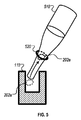
磁石130によって加えられる引力の大きさは、細胞に付着した粒子の磁性特性、磁石130の強度、および/またはマイクロウェルチップ110に対する磁石130の配置に基づいて調整することができる。例えば、磁石130は、マイクロウェルチップ110からの磁石の距離を変化させることができ、それによって、マイクロ流体チャンバ内の標的実体に印加される磁力を変化させることができるように、外部ボディと関連付けることができる。次いで、印加される磁力は、特定のタイプの標的実体または使用される特定のタイプの官能化磁性ビーズに対して較正することができる。さらに、磁石130は、システム100のためのプロトコルに従って完全に磁力を除去するように移動させることができる。磁力の除去を使用して、捕捉された標的実体のマイクロウェル内での除去を容易にし、以て、標的実体を別個の収集容器へと輸送または流すことができる。一実施態様では、磁石130または別の磁石をチップの上に配置して、マイクロウェルから細胞を抽出するのを助けることができる。次に、上部に配置された磁石130は、マイクロウェルアレイ内の細胞の連続抽出のために横方向に移動させることができる。
The magnitude of the attractive force applied by the
いくつかの実施態様では、磁石130は、マイクロウェルチップ110の一部を覆うようにマイクロウェルチップ110の下に配置された電磁石のアレイを含む。次いで、アレイ内の1つまたは複数の電磁石は、マイクロウェルチップ110の表面に沿った指定される経路に沿う細胞の動きを引き起こすための引力を加えるために、特定の順序で選択的に電力供給され得る。
In some embodiments, the
分析デバイス140は、光学的技法を用いて、チャンバ表面のマイクロウェル内に捕捉された細胞を分析するように構成することができる。例えば、分析デバイス140は、他の既知の技法の中でも、蛍光、明視野、暗視野、ノマルスキ、質量分光法、ラマン分光法、表面プラズモン共鳴に基づく様々な顕微鏡技法を使用するように構成することができる。
分析デバイス140は、CCDカメラおよびコンピュータ化画像取得・分析システムを含むことができる。CCDカメラは、マイクロウェルチップ110内のすべてのマイクロウェルから画像を取得するように、マイクロウェルチップ110の全領域のサイズをカバーするのに十分に大きくすることができる。代替的に、CCDカメラは、1つのマイクロウェルまたはマイクロウェルのグループのみを含むより小さい視野を分析することができる。そのような実施態様では、CCDカメラまたはチップ100は、手作業で、または並進ステージもしくは他のコンピュータ制御モダリティを使用して、CCDカメラを他のマイクロウェルと順次整列させ、それらの画像を取得するように動かすことができる。
The
分析デバイス140は、マイクロウェルチップ110を使用する様々な態様の細胞捕捉プロセスを分析するために使用することができる。例えば、分析デバイス140を使用して、マイクロウェルチップ110のマイクロウェルから抽出された細胞を分析することができる。代替的に、分析デバイス140は、細胞抽出の前に、マイクロウェルチップ110のマイクロウェル内の細胞捕捉を視覚化および/または確認するために、付加的または代替的に使用することができる。
細胞分析システム100は、任意選択的に、コントローラ150を含むことができる。コントローラ150は、本明細書に記載された方法の様々なステップ、例えばサンプル流体注入、細胞捕捉、捕捉された細胞の抽出、および/または捕捉された細胞の分析のために、マイクロウェルチップ110で実行される動作を自動化するために使用され得る。一実施例では、コントローラ150を使用して、各マイクロウェルの内容物の画像を記録するための分析デバイス140の視野に対する、または、捕捉された細胞の抽出のためのマイクロピペットに対する、マイクロウェルチップ110の位置を調整する並進ステージの位置を調整することができる。別の実施例では、コントローラ150は、特定のタイプのサンプル流体に対する細胞捕捉技法をカスタマイズするために、磁石130の位置および生成される引力の大きさを調整するコンピュータ実装命令を生成することができる。
The cell analysis system 100 can optionally include a controller 150. The controller 150 is on the
コントローラ150は、特定の標的実体、認識要素、およびサンプルサイズに対する制御されたフロープロトコルに従うように構成されたマイクロプロセッサであってもよい。コントローラ150は、特定の1つまたは複数のサンプルに関連付けられた指標を読み取り、特定のサンプルに関連付けられる所定のフロープロトコルを自動的にアップロードおよび実行するためのリーダを組み込むことができる。コントローラ150はまた、標的実体の捕捉を容易にし、未結合磁性ビーズをマイクロウェルのアレイに引き込むために、検出サイクル中に磁場を変調することもできる。 Controller 150 may be a microprocessor configured to follow a controlled flow protocol for specific target entities, recognition elements, and sample sizes. Controller 150 can incorporate a reader to read the indicators associated with a particular sample or samples and automatically upload and execute a given flow protocol associated with a particular sample. Controller 150 can also modulate the magnetic field during the detection cycle to facilitate capture of the target entity and to draw unbound magnetic beads into the array of microwells.
コントローラ150は、ユーザ制御操作を可能にするように構成することもできる。例えば、ビーズをマイクロウェルチップ110の表面に引き付けることがもはや不可能になるまで、結合した標的細胞サンプルの流量を増加させることによって、特定の標的細胞と磁性ビーズとの組み合わせに対する流量を決定することができる。システム100の連続的な動作は、流れのバイパスが必要であるか否か、または検出プロセスが完了したか否かを判定するために、可視化窓を通して直接観察することができる。コントローラ150はまた、分析デバイス140がマイクロウェルチップ110の様々な区画で画像を走査して取得することを可能にするようにマイクロウェルチップ110を移動させることもできる。次いで、これらの画像を使用して、マイクロウェルチップ110の表面の全体または一部の画像を再構成することができる。
The controller 150 can also be configured to allow user control operations. For example, determining the flow rate for a particular target cell and magnetic bead combination by increasing the flow rate of the bound target cell sample until it is no longer possible to attract the beads to the surface of the
マイクロウェル配列
図1Aは、マイクロウェルチップ110内のマイクロウェルのアレイの一実施例を示す。図示されているように、マイクロウェルチップ110は、マイクロウェルの3つの別個のアレイ112,114、および116を含み、各アレイ内のマイクロウェルはすべて、同じまたはほぼ同じサイズ、例えば直径、断面積、深さ、形状および/または総容積であるが、異なるアレイにおけるマイクロウェルのサイズ、例えば直径は異なる。例えば、マイクロウェルアレイ112内のマイクロウェル102aは、個々の細胞または最小の標的実体を捕捉するために使用され、マイクロウェルアレイ114内のマイクロウェル102bは、直径が幾分大きく、小さい細胞クラスタまたはより大きい単一の細胞を捕捉するために使用することができ、マイクロウェルアレイ116内のマイクロウェル102cは最大の直径を有し、大きい細胞クラスタまたはさらにはより大きい単一の細胞を捕捉するために使用することができる。他の実施態様では、マイクロウェルチップは、マイクロウェルのすべてがほぼ同じサイズを有する1つのみのアレイを有することができる。
Microwell Array FIG. 1A shows an example of an array of microwells in a
マイクロウェルチップ110の表面上のマイクロウェル102a、102b、および102cの入口のサイズは、単一の細胞または細胞クラスタのみがマイクロウェル内に捕捉されるように構成することができる。マイクロウェル102a、102b、および102cはまた、マイクロウェル内で単一の細胞または細胞クラスタが捕捉されると、流体サンプルがマイクロ流体チャンバを通じて入口ポートから出口ポートへと流れ続けても、または、磁石130によって印加される引力がない状態でもマイクロウェル内にとどまるように十分な深さをも有する。
The size of the inlets of the microwells 102a, 102b, and 102c on the surface of the
一実施態様では、複数の細胞の積み重なりを防止するように、各マイクロウェルの深さが制限される。マイクロウェルの深さは、標的細胞の公称直径と、標的細胞の公称直径の2倍未満との間であり得る。一実施例として、循環腫瘍細胞の直径は約15マイクロメートルである。マイクロウェルの深さは、15〜30マイクロメートルであり得る。別の実施例として、細菌のサイズは約1マイクロメートルであり、マイクロウェルの深さは1〜2マイクロメートルであり得る。別の実施形態では、マイクロウェルの深さは、細胞がマイクロウェルの内側に入り、下向きの磁力の影響を受けるようになると、その厚さが減少し得、一方でその幅は増加し得る可能性があると仮定して、細胞の公称直径に等しくすることができるか、またはさらには細胞の公称直径よりも5,10,20または50%だけ小さくすることができる。これらの場合、マイクロウェルの深さは、第1の細胞がすでにマイクロウェル内にあるとき、第1の細胞の上で一致する別の第2の細胞がその一部をマイクロウェルの外側に露出させ、結果、第1の細胞が洗い流されるのを防止しながら、流れまたは横方向の磁力によって洗い流されることができるように構成することができる。15マイクロメートルの循環腫瘍細胞(CTC)の例では、マイクロウェルの深さは1マイクロメートルから15マイクロメートルの間であり得る。マイクロウェルの深さは、捕捉/分離しようとする標的細胞または細胞クラスタの公称の大きさに応じて構成される必要があり、したがって、実際のデバイスにおけるマイクロメートル単位のマイクロウェルの特定の深さは、ここに記載されているものとは異なるものであり得ることが理解されるべきである。さらに、いくつかの実施態様では、マイクロウェルの深さは、アレイ毎にまたは同じアレイ内で異なるように製造される。 In one embodiment, the depth of each microwell is limited to prevent stacking of multiple cells. The depth of the microwell can be between the nominal diameter of the target cell and less than twice the nominal diameter of the target cell. As an example, the diameter of circulating tumor cells is about 15 micrometers. The depth of the microwell can be 15-30 micrometers. As another example, the size of the bacterium can be about 1 micrometer and the depth of the microwell can be 1-2 micrometers. In another embodiment, the depth of the microwell can decrease as the cell enters the inside of the microwell and becomes affected by the downward magnetic force, while its width can increase. It can be equal to the nominal diameter of the cell, or even 5, 10, 20 or 50% smaller than the nominal diameter of the cell, assuming it is of sex. In these cases, the depth of the microwell is such that when the first cell is already in the microwell, another second cell that matches on the first cell exposes a portion of it to the outside of the microwell. As a result, it can be configured to be flushed by a flow or lateral magnetic force while preventing the first cells from being flushed. In the example of a 15 micrometer circulating tumor cell (CTC), the depth of the microwell can be between 1 micrometer and 15 micrometer. The depth of the microwells must be configured according to the nominal size of the target cell or cell cluster to be captured / isolated, and therefore the specific depth of micrometer microwells in the actual device. It should be understood that can be different from what is described here. Moreover, in some embodiments, the depth of the microwells is manufactured to vary from array to array or within the same array.
一実施態様では、磁力およびマイクロウェル間の間隔は、磁性化実体が凝集する可能性、したがって複数の磁性実体が同じマイクロウェルに入る可能性を最小にするように調整される。 In one embodiment, the magnetic force and the spacing between the microwells are adjusted to minimize the possibility of magnetic entities agglomerating and thus multiple magnetic entities entering the same microwell.
一実施態様では、マイクロウェルの寸法は、マイクロ流体チャンバを通る乱流の適用を受けて、捕捉された細胞がマイクロウェルから放出され得るように構成される。例えば、サンプル流体の流量、マイクロウェルの深さ、および磁石130によって印加される引力の大きさは、マイクロウェル内に捕捉された細胞を、印加される引力またはサンプル流体の流体流量のいずれかを調整することによって、制御された様式で抽出され得るように、注意深く選択および制御することができる。いくつかの実施態様では、個々の細胞または細胞クラスタは、流体流の存在または不在下で、手動またはコンピュータ制御様式のいずれかでピペットによって取り出される。
In one embodiment, the dimensions of the microwells are configured so that captured cells can be released from the microwells under the application of turbulence through the microfluidic chamber. For example, the flow rate of the sample fluid, the depth of the microwell, and the magnitude of the attractive force applied by the
一実施例として、マイクロウェルチップ110内に捕捉される細胞が直径10〜20マイクロメートルの白血球である場合、マイクロウェルチップ110の表面上のマイクロウェル102aの入り口は、15〜30マイクロメートルであり得る。代替的に、他の事例では、入口の大きさは、磁石130によって加えられる引力によってマイクロウェル内に細胞が押し込まれるように、細胞直径と等しいかまたは5〜20%小さくすることができる。別の実施例として、捕捉される細胞は直径10〜20マイクロメートルの循環腫瘍細胞であり得、マイクロウェルチップ110の表面上のマイクロウェル102aのマイクロウェルの入り口は、10〜35マイクロメートルであり得る。別の例として、捕捉される細胞は、6〜8マイクロメートルの直径を有する赤血球であり得る。この場合、マイクロウェルチップ110の表面上の102のマイクロウェル入り口は、6〜10マイクロメートルとすることができる。別の実施例として、捕捉される細胞は直径約1マイクロメートルの細菌であり得、マイクロウェルチップ110の表面上のマイクロウェル102aのマイクロウェルの入り口は、1〜2マイクロメートルであり得る。さらに別の例として、捕捉される細胞は、直径が50〜100ナノメートルに及ぶエキソソームであり得、マイクロウェルチップ110の表面上の102aのウェルの入口は、50nmより大きくなり得る。
As an example, where the cells captured within the
図1Aに示す実施例では、マイクロウェル116のアレイなどのより大きい入口を有するマイクロウェルは、マイクロウェル112のアレイのようなより小さい入口を有するマイクロウェルに対して、マイクロ流体チャンバ内で入口ポートの下流に配置される。このようなマイクロウェル構成では、マイクロウェルチップ110の下の磁石130は、マイクロウェルチップ110の一方の側、例えば、左側からマイクロウェルチップの他方の側、例えば右側に動かすことができ、以て、より小さい個々の細胞(または最小の標的実体)が最初にマイクロウェル112のアレイに捕捉され、一方で、より大きい細胞ならびにより小さいおよびより大きい細胞クラスタは、大きすぎてマイクロウェル112のアレイの入口を通じて収まることができないため、磁石130の経路に沿って下流に進む。
In the embodiment shown in FIG. 1A, a microwell with a larger inlet, such as an array of
いくつかの実施態様では、マイクロウェルの底部は、捕捉された細胞を保持しながら、マイクロウェルから液体および未結合磁性ビーズを通過させることができる1つまたは複数の細孔または開口を含む。そのような実施態様では、細胞がマイクロウェル内に捕捉されると、マイクロウェルを通して流体を導入して、捕捉された細胞を洗浄することができる。一実施例では、洗浄ステップを使用して、細孔を通じて自由な未結合の磁性ビーズおよびマイクロウェル内に捕捉された他の小さい実体を篩い分けることができる。 In some embodiments, the bottom of the microwell comprises one or more pores or openings that allow liquid and unbound magnetic beads to pass through the microwell while retaining captured cells. In such an embodiment, once the cells are trapped in the microwells, fluid can be introduced through the microwells to wash the trapped cells. In one embodiment, a wash step can be used to sieve free unbound magnetic beads through the pores and other small entities trapped in microwells.
マイクロウェルチップの長さがその幅よりも不釣合いに大きくなることを必要とする多くのマイクロウェルアレイを有するいくつかの実施態様では、マイクロウェルアレイは、直線状に配置される代わりに、蛇行したパターンで配置することができ、より多くのマイクロウェルを矩形表面上に詰めることができる。 In some embodiments with many microwell arrays that require the length of the microwell tip to be disproportionately greater than its width, the microwell array meanders instead of being arranged linearly. More microwells can be packed on a rectangular surface.
図1Bは、マイクロウェルチップ110の入り口ポート付近で上流に配置されたマイクロウェル118のアレイを含むマイクロウェルチップ110の実施態様を示す。マイクロウェル102dは、サンプル流体内の自由な未結合磁性ビーズを捕捉するために使用することができる。これらのマイクロウェルの寸法は、磁性ビーズを捕捉するのに十分に大きいが、流体サンプル中の細胞がマイクロウェル102dに入ることができないほど十分に小さくなるようにも構成することができる。そのような実施態様では、最初に、これらのマイクロウェルの周りで磁石130を移動させて、マイクロウェル102d内での捕捉のために未結合の磁性ビーズに引力を加えることができる。
FIG. 1B shows an embodiment of a
図1C−1、図1C−2、図1C−3、および図1C−4は、マイクロウェル形状の実施例を示す断面図である。図1C−1は円柱状マイクロウェルの実施例を示し、図1C−2は円錐状マイクロウェルの実施例を示し、図1C−3は円錐台マイクロウェルの実施例を示し、図1C−4は逆円錐台マイクロウェルの実施例を示す。円錐台形状の場合、マイクロウェルの入口は大きい直径を有することができ、一方、マイクロウェルの底部はより小さい直径を有することができる。代替的に、逆円錐台形状の場合、マイクロウェルの入口は、細胞がマイクロウェルから逃げるのがより困難になるように、マイクロウェルの底部と比較してより小さい直径を有することができる。この構成は、マイクロウェルチップ全体が液体中にあるのではなく、そのマイクロウェルが液体を含む場合、液体を長期間保持するのにも役立つ。 1C-1, FIG. 1C-2, FIG. 1C-3, and FIG. 1C-4 are cross-sectional views showing examples of microwell shapes. 1C-1 shows an example of a columnar microwell, FIG. 1C-2 shows an example of a conical microwell, FIG. 1C-3 shows an example of a truncated cone microwell, and FIG. 1C-4 shows an example of a truncated cone microwell. An example of an inverted truncated cone microwell is shown. In the case of a truncated cone shape, the inlet of the microwell can have a large diameter, while the bottom of the microwell can have a smaller diameter. Alternatively, in the case of an inverted cone shape, the inlet of the microwell can have a smaller diameter compared to the bottom of the microwell so that cells are more difficult to escape from the microwell. This configuration also helps to retain the liquid for extended periods of time if the entire microwell tip is not in the liquid and the microwell contains the liquid.
図2Aは、マイクロ流体チャンバ内の磁気誘導細胞捕捉の一実施例を示す。この図は、チャンバ内に位置するマイクロウェルチップ110の側断面図を示し、チャンバの入口ポート(図示せず)がマイクロウェルチップ110の左側に配置されており、チャンバの出口ポート(図示せず)がマイクロウェルチップ110の右側に配置されている。この実施例では、磁石130は、マイクロウェルチップ110の下に配置され、個々の細胞(または最小の標的実体)202a、小さい細胞クラスタ202b、および大きい細胞クラスタ202cを、マイクロウェルチップ110の表面上の異なるマイクロウェルチップに捕捉するのを支援する引力212を生成する。磁石130は、個々の細胞202aを捕捉するために、最初に上流(例えば、マイクロウェルチップ110の左側)に配置される。個々の細胞がマイクロウェル(例えば、マイクロウェル110のアレイ)内に捕捉された後、磁石130は、小さい細胞クラスタ202bおよび大きい細胞クラスタ202cを捕捉するために下流に移動される。
FIG. 2A shows an example of magnetically induced cell capture in a microfluidic chamber. This figure shows a side cross section of the
一実施態様では、標的実体は、入口ポートを通る流体流によって導入することができ、標的実体が第1のアレイ上に実質的に配置されている間、より小さい標的実体が下流に逃げ、誤って後続のアレイのより大きいウェルに入るのを防止するように、流体流を停止または減少させることができる。磁石は、例えば、第1のアレイのウェルに小さい標的実体(または個々の細胞)が入るのを確実にするために、振動するように、例えば水平方向に動かすことができる。次に、より大きい実体(またはクラスタ)を次のアレイのより大きいウェルに導くために、磁石を下流に移動することができる。このプロセスは、流体流を再開または増加させることによって、または代替的に流体流を一切用いずに支援することができる。ウェル内に実体を捕捉するプロセスが完了すると、必要に応じて洗浄プロセスを実行することができる。一実施態様では、入口ポートおよび出口ポートは、本質的にマイクロウェルチップ110の一部であってもよい。
In one embodiment, the target entity can be introduced by a fluid flow through the inlet port, and while the target entity is substantially located on the first array, the smaller target entity escapes downstream, erroneously. The fluid flow can be stopped or reduced to prevent it from entering the larger wells of subsequent arrays. The magnet can be moved, for example, horizontally to vibrate, for example, to ensure that small target entities (or individual cells) enter the wells of the first array. The magnet can then be moved downstream to guide the larger entity (or cluster) to the larger well of the next array. This process can be assisted by resuming or increasing the fluid flow, or as an alternative, without any fluid flow. Once the process of capturing the entity in the well is complete, a cleaning process can be performed as needed. In one embodiment, the inlet and outlet ports may be essentially part of the
磁石は、マイクロウェルチップ110のマイクロウェル内での細胞捕捉を改善するために、様々な運動パターンに従うために、手動または自動のいずれかでマイクロウェルチップの下の2つの次元に沿って(例えば、図1A〜図1Bに示すx軸およびy軸に沿って)マイクロウェルチップ110の下に移動させることができる。例えば、磁石は、単一軸に沿った前後のパターンにおいて移動して、マイクロウェルチップ110のある領域にわたって引力を繰り返し印加することができる。他の時例では、円形パターン、ジグザグパターン、ラスタスキャン、S字状、または他のパターンなどの他のパターンも使用することができる。いくつかの実施態様は、捕捉されるべき細胞の特性に基づくより洗練された運動パターンの使用を含む。例えば、運動パターンは、マイクロウェルチップ110の下での磁石の動きを調整する制御ユニットから、ユーザによって外部で定義および制御され得る。一実施態様では、マイクロウェルチップ110を収容するハウジングは、磁石に接続されたハンドルを有するように構成することができる。このハンドルは、磁石の手動運動を可能にするのに十分な量だけハウジングの外側に延在することができる。
The magnets are either manual or automatic along the two dimensions below the microwell tip to follow various motion patterns to improve cell capture within the microwell of the microwell tip 110 (eg,). Can be moved below the microwell tip 110 (along the x-axis and y-axis shown in FIGS. 1A-1B). For example, the magnet can move in an anteroposterior pattern along a single axis to repeatedly apply attractive force over a region of the
本明細書に記載されるように、引力212の大きさは、細胞202a、小さい細胞クラスタ202b、および大きい細胞クラスタ202cのマイクロウェルへの磁気誘導運動を増減するように調整することもできる。例えば、磁石130は、より小さい引力を印加してマイクロウェル内に捕捉されるべき個々の細胞202aを誘導するためにより小さい引力を印加するように動かしまたは制御することができ、細胞クラスタのより大きいサイズに起因して、マイクロウェル内に捕捉されるべき細胞クラスタを誘導するためにより大きい引力を印加するように動かしまたは制御することができる。いくつかの事例において、特定のサイズまたは形状の細胞および/または細胞クラスタを選択的に捕捉する(例えば、小さい細胞クラスタ202bを選択的に捕捉するが、大きい細胞クラスタ202cは捕捉しない)ように、引力212の大きさを特異的に調節することができる。例えば、磁石130が永久磁石である場合、磁石130は、印加される磁力の大きさを増加させるためにマイクロ流体チャンバからより近づくことができ、印加される磁力の大きさを減少させるために、マイクロ流体チャンバからさらに遠ざけることができる。一実施態様では、磁石とチップ表面の底部との間の距離は、10マイクロメートルと2センチメートルの間、またはより狭くは0.5から2ミリメートルの間とすることができる。磁石130が電磁石である他の例では、同様に、磁石130に供給されるエネルギーの量を増加させて、印加される磁力の大きさを対応して増加させ、または、エネルギーの量を減少させて、印加される磁力の大きさを対応して減少させることができる。一実施形態では、単一の磁性、常磁性または超常磁性粒子に及ぼされる力は、0.1pN〜1nNまたはより狭くは1〜100pNであり得る。
As described herein, the magnitude of the
いくつかの実施態様では、マイクロウェルチップ110の表面は、マイクロウェル内での捕捉された細胞の動きを調整するために、マイクロ流体チャンバ内に電場を生成することができる。例えば、マイクロウェルチップ110は、捕捉された細胞がマイクロウェルから出るように、マイクロウェルチップ110内に捕捉された負に帯電した細胞に反発する、マイクロウェルの底面上の電場を生成する埋め込みモダリティ(例えば、電磁石または発電器)を有することができる。生成された電場の大きさは、捕捉された細胞に対して特定の操作を行うように調節することができる。例えば、捕捉後にマイクロウェル内に導入される色素、染色剤、溶解物などの化学物質との混合を増進するために、マイクロウェル内の細胞の配置を調整するために(例えば、マイクロウェル内で細胞を振動または攪拌することができる)小さい電場を生成することができる。別の例では、マイクロウェルから細胞を移動させ、マイクロ流体チャンバの出口ポートを通じて細胞を収集するために、大きい電場を発生させることができる。いくつかの実施態様では、標的実体に結合するために使用される粒子またはビーズは、外部電場によって標的実体を引き付けるまたは反発するのに役立つように負または正の電荷を帯びることができる。いくつかの実施形態では、標的実体上の電場から生じる力の大きさは、0.01pN〜1nNの間であり得る。
In some embodiments, the surface of the
図2Bは、マイクロウェルチップ上のマイクロウェルのアレイの一実施例を示す。図示の実施例では、アレイは、列に含まれるマイクロウェルが先行する列のマイクロウェルに対してオフセットされるように、距離130だけ各々オフセットされた連続した列として構成される。この距離130は、例えば、1,5または10マイクロメートルであり得る。このタイプの構成は、標的実体が、図2Cでより詳細に示されているマイクロウェルチップ表面にわたる流体運動、例えば水平運動中にマイクロウェル内に捕捉される確率を高めるために使用することができる。
FIG. 2B shows an example of an array of microwells on a microwell chip. In the illustrated embodiment, the array is configured as a continuous row offset by a distance of 130 so that the microwells contained in the row are offset relative to the microwells in the preceding row. This
図2C−1および図2C−2は、マイクロウェルアレイの2つの例、および、マイクロチップの表面にわたる水平流体流中のマイクロウェル内での標的実体捕捉へのそれらの影響を示す。例えば、図2C−1のチップ210は、マイクロウェルが互いに対して水平方向および垂直方向に平行に配置された格子状アレイを含む。このタイプの構成によって、マイクロウェルがチップ210の表面上にまばらに離間している場合、標的実体は、マイクロウェルの2つの平行な行の間で離間されている表面の部分にそって流れるので、チップ表面と接触している間に、磁力および/または流体力によって引き起こされる水平流体流または水平運動の間にいくつかの標的実体を捕捉することができない場合がある。したがって、マイクロウェルのこの構成は、標的実体がチップ210の表面にわたって流れるときに、マイクロウェルが標的実体の水平経路に含まれる全体的な尤度を低減することができる。
2C-1 and 2C-2 show two examples of microwell arrays and their effect on target entity capture within microwells in a horizontal fluid stream over the surface of the microchip. For example,
対照的に、図2C−2に示されるチップ220は、図2Bに示されるアレイと同様の交互アレイを含み、異なる列のマイクロウェルは、最も近い列のマイクロウェルから垂直方向にオフセットされる。このタイプの配置では、標的実体がマイクロウェルに行き当たることなくチップ220の表面を通過する尤度は、チップ210の表面上の尤度と比較して低減される。これに関して、マイクロウェルアレイのこの構成は、マイクロウェルチップの表面上に配置されるマイクロウェルの密度を必ずしも増加させることなく、捕捉効率を改善するために使用することができる。例えば、図2Cに示された例では、チップ220は、類似またはより少ない数のマイクロウェルを含むが、標的実体が水平通過の間にマイクロウェルに行き当たる確率が増加することによって、捕捉効率が増加し得る。様々な実施態様において、0%(例えば、チップ210に示されるようにオフセットがない)と100%(例えば、マイクロチップの直径に等しいオフセット)との間、または、例えば、マイクロウェルの直径の150%または200%の距離だけより大きく、もしくは、マイクロウェルの直径の約10%、25%、50%、または75%の距離だけより小さく調整することができるオフセット距離に基づいて、捕捉効率をさらに調整することができる。オフセットは、細胞がウェルと重なる確率を最大にするためにできるだけ小さくすることもできる。例えば、図2C−2に示すように、オフセットがマイクロウェルの直径とほぼ同じである場合、細胞の水平経路が正確にマイクロウェルの連続した行の間に正確に存在する可能性が依然としてあり得る。これが起こると、細胞がマイクロウェルの入口と部分的にしか重ならないため、細胞は依然としてマイクロウェルに入らない可能性がある。
In contrast, the chip 220 shown in FIG. 2C-2 contains an alternating array similar to the array shown in FIG. 2B, with microwells in different rows being offset vertically from the microwells in the nearest row. In this type of arrangement, the likelihood that the target entity will pass through the surface of the chip 220 without hitting the microwell is reduced compared to the likelihood on the surface of the
図2Dは、マイクロウェルの形状が正方形または長方形であるマイクロウェルアレイの一実施例を示す。この例では、チップ230は、非特異的吸着および/または磁気的凝集を介してクラスタ化された個々の細胞を分解するのに役立ち得る正方形または長方形のマイクロウェルを含む。この構成は、大きいクラスタがチップ230の表面に沿って移動する際に、個々の標的実体または凝集体の部分を捕捉するために、異なるサイズのマイクロウェルを含むことができる。例えば、大きいクラスタがチップ230の表面に沿って移動すると、クラスタから分離された個々の標的実体は、チップ230の左側の近くの最小のマイクロウェルに捕捉され得、一方、分離された中間サイズのクラスタは、チップ230の中心付近の中型のマイクロウェル内に捕捉され得る。マイクロウェル間の間隔は、クラスタを分離する際のマイクロウェルの影響を高めるために使用することができる。例えば、チップ230の表面上のマイクロウェルの縁部間の距離は、大きいクラスタに対する分解効果を高めるために最小限に抑えることができる。
FIG. 2D shows an example of a microwell array in which the shape of the microwell is square or rectangular. In this example,
図2Eは、矩形のマイクロウェルがクラスタ240に対して有することができる分解効果を示す概略図である。この実施例では、クラスタ240は、2つのマイクロウェルの下に配置された磁石130によって磁力に曝される2つの個々の標的実体を含む。図示されているように、クラスタ240がマイクロウェルチップの表面に向かって移動すると、矩形のマイクロウェルによって形成された縁部が、クラスタ240の個々の標的実体を可能性として分離し、異なるマイクロウェル内の各実体を捕捉することができる。この分解効果は、円筒状のマイクロウェル(すなわち、円形開口を有するマイクロウェル)でも生じ得るが、矩形のマイクロウェルで増強される。いくつかの実施態様では、ウェルの開口は五角形、六角形、八角形または三角形であってもよい。
FIG. 2E is a schematic diagram showing the decomposition effect that a rectangular microwell can have on cluster 240. In this embodiment, the cluster 240 comprises two individual target entities exposed to magnetic force by a
図2Fは、磁性または磁性化標的実体を分解および/または分離する技法の一実施例の概略図である。この例では、3つの標的実体細胞からなる標的実体クラスタ252の周りにリング状の磁石250が配置されている。クラスタ252を形成する個々の標的実体を分離および/または分解するのを助けるために、磁石250によって加えられる外向きの磁力。一実施態様では、磁石250は、クラスタ252などのクラスタを分解しながら、磁性化標的実体を集合的にマイクロウェルに引き込む、下向きの磁力および外向き放射状磁力の両方を印加するために、マイクロウェルチップの下に配置される。他の実施態様では、磁石250は、マイクロウェルチップ.1の表面に向かって下向きの磁力を必ずしも印加することなく、標的実体を分離および/または分解するためだけに、主に外向きの放射状磁力を印加するために、マイクロウェルチップの表面と実質的に同一平面上に置くことができる。
FIG. 2F is a schematic representation of an embodiment of a technique for decomposing and / or separating a magnetized or magnetized target entity. In this example, a ring-shaped
図2Gは、対称な、例えば円形の基板260を有するマイクロウェルアレイデバイスの概略図である。円形基板260は、マイクロウェルがない中心位置の周りに同心円アレイ状のマイクロウェルを含む。流体サンプルは、例えば入口262aを介して、またはピペットによって、基板の中央の中心位置に加えられ、例えば、デバイスが適切な速度でスピンされて、液体サンプルが流れるようにされ、および/または標的実体が適切な流量/速度で移動されるときに、中心からマイクロウェルにわたって半径方向外向きに流れて、デバイスの縁部にある出口262bに至るようにされる。流体サンプルは、清浄な、例えば乾燥したマイクロウェルアレイデバイスに加えることができ、または緩衝剤または他の流体が、例えば表面およびマイクロウェルを「プライミング」して、例えば、マイクロウェル内の気泡を除去するために基板表面に施与された後に、加えることができる。
FIG. 2G is a schematic representation of a microwell array device with a symmetrical, eg,
流体サンプル中の標的実体の流れは、システムの入口および/もしくは出口に配置されたポンプおよび/もしくは真空によって生成され得るか、または、流れは、対称な、例えば円形または八角形の基板を回転させることによって生成され得る。例えば、基板の直径は、3mm〜30cm、例えば、2cm〜10cm(例えば、3,4,5,6,7,8,9,10,15,20,25,30,40,50,75,もしくは100mmまたは1,2,3,4,5,6,7,8,9,10,15,20,25,もしくは30cm)に及ぶことができる。一実施態様では、基板の回転速度は、0.0001rpm〜1000rpm、例えば0.01rpm〜20rpm(例えば、0.0001,0.0005,0.001,0.005,0.01,0.05,0.1,0.5,1.0,2.5,5,7.5,10,12.5,15,17.5,20,25,30,40,50,75,100,200,250,250,500,750,または1000rpm)に及ぶことができる。 The flow of the target entity in the fluid sample can be generated by pumps and / or vacuums located at the inlet and / or outlet of the system, or the flow rotates a symmetrical, eg, circular or octagonal substrate. Can be generated by For example, the diameter of the substrate is 3 mm to 30 cm, for example, 2 cm to 10 cm (for example, 3,4,5,6,7,8,9,10,15,20,25,30,40,50,75, or It can range from 100 mm or 1,2,3,4,5,6,7,8,9,10,15,20,25, or 30 cm). In one embodiment, the rotational speed of the substrate is 0.0001 rpm to 1000 rpm, eg 0.01 rpm to 20 rpm (eg 0.0001, 0.0005, 0.001, 0.005, 0.01, 0.05, 0.1, 0.5, 1.0, 2.5, 5, 7.5, 10, 12.5, 15, 17.5, 20, 25, 30, 40, 50, 75, 100, 200, It can range from 250, 250, 500, 750, or 1000 rpm).
この実施態様では、マイクロウェルのアレイは、最小のマイクロウェル266の円(または複数の円)がデバイスの中心の最も近くに配置され、最大のマイクロウェル264の円(または複数の円)がデバイスの中心から最も遠くに配置された同心円として構成される。1つの磁石を基板の下に配置して、磁性標的実体をマイクロウェルに入れ、マイクロウェル内に保持させることができる。代替的に、1つまたは複数の磁石を、例えば基板に隣接して、例えば基板の下に配置し、標的実体を、マイクロウェルの次の円形アレイに向かって、例えば半径方向外向きに移動させるように移動されるように構成および制御することができる。いくつかの実施形態では、例えば円形電磁石または一連の円形電磁石などの電磁石を、例えば基板の下に配置することができ、標的実体をデバイスの表面上で動かすために、半径方向外向きの方向に磁力を提供するように順次トリガすることができる。
In this embodiment, the array of microwells has the
細胞捕捉・分析システム
マイクロウェルチップ110は、マイクロウェルチップ上を流れる、例えば、マイクロ流体チャンバの底部にある別個の取り外し可能なプレートとしての、またはチャンバの底壁の一部として形成されるマイクロウェルチップを含むマイクロ流体チャンバを通じて流れる流体サンプル内の細胞などの標的実体の捕捉を可能にする様々な特徴を含むことができる。例えば、マイクロウェルチップ110は、マイクロ流体チャンバの特定の位置内で細胞を捕捉することを可能にするために、流体サンプルの流れを調整する構造的特徴を含むことができる。一実施例として、マイクロウェルチップ110は、細胞成分からの流体の分離を支援する所定の構成にある分岐および/または弁を有する流体回路を含むことができる。他の事例では、マイクロウェルチップの表面を官能化するために使用される特定の化学物質と、標的細胞の表面上に発現される受容体との間の受容体−リガンド結合を使用して細胞捕捉を増強するために、マイクロウェルチップ110の表面を官能化することができる。場合によっては、特定のタイプの細胞および分子を認識するために、マイクロウェルを選択的に官能化することができる。例えば、マイクロウェルの内壁は、マイクロウェル内に標的実体を保持するのを支援するために、本明細書に記載されるような結合部分でコーティングおよび/または官能化され得る。いくつかの実施態様では、構造特徴(例えば、チャネルの寸法およびチャネルの構成)および機能的特徴(例えば、チャネルの表面および/またはマイクロウェルの内面に結合される結合部分)の組み合わせが、マイクロウェルチップ110内での細胞捕捉を増強するために使用される。
Cell capture and analysis system The
マイクロウェルチップ製造
マイクロウェルチップ110は、フォトリソグラフィおよびエッチングのようなシリコンに一般的に使用されている微細加工技法を用いて製造することができる。場合によっては、マイクロウェルチップ110は、捕捉された細胞の観察および分析を可能にする透明な上面を有する流体チャンバの内部に位置する単一の表面構造である。他の例では、マイクロウェルチップ110は、複数の予め製造された層を組み合わせることによって構築され、ここで、最上層(およびいくつかの実装態様では最下層)は、ガラス、石英、またはプラスチック(例えば、アクリル、ポリ塩化ビニル、ポリプロピレンまたはポリスチレン)などの透明材料から作製されるか、または、そのような材料からなる窓を含む。このような場合、マイクロウェルチップ110は、図1Aに示すようなマイクロウェルの構成を含む最下層と、マイクロ流体チャンバの高さまたは側壁を形成するスペーサ層と、マイクロ流体チャンバを取り囲む最上層とを含むことができる。図3A〜図3Bに関してより詳細に説明するように、いくつかの例では、マイクロウェルチップ110の最上層は、捕捉された細胞の抽出を可能にするように取り外し可能であり得る。いくつかの実施態様では、各マイクロウェルの底部は、透明な材料から作製されているか、または透明な材料の窓を含むことができる。
Microwell Chip Manufacture The
いくつかの実施態様では、マイクロウェルチップ110のマイクロウェルは、最初にポリジメチルシロキサン(PDMS)フィルム内に孔を形成し、次いでそのフィルムをガラスなどの固体材料の表面に被着させることによって構築される。そのような実施態様では、細胞を捕捉するために使用されるマイクロウェルを形成するように、固体材料の底部の貫通孔を「キャップ」するために、PDMSフィルムを固体表面上に配置することができる。
In some embodiments, the microwells of the
一実施態様では、マイクロウェルチップ110は、ポリメラーゼ連鎖反応(PCR)を含む用途のための温度制御のための効率的な伝導を可能にするために、アルミニウムまたはステンレス鋼などの金属から作製することができる。マイクロウェルチップは、金または白金、またはチオールを含む他の分子による官能化を可能にする同様の材料でコーティングまたはパターン化することができる。
In one embodiment, the
いくつかの実施態様では、マイクロウェルチップ110の表面積は、100μm2〜1000cm2またはより狭くは0.01mm2〜100mm2に及び得る。一実施態様では、マイクロウェルチップ110のサイズは、成人の手のサイズに相当するように、15cm×10cmにすることができる。マイクロウェルチップ110は、30マイクロメートルの入口直径を有し、40マイクロメートルの中心間距離を有するマイクロウェルから構成することができる。この実施態様では、マイクロウェルチップは、約600万個のマイクロウェルを有することができる。別の実施態様では、マイクロウェルチップ110は、20cm×15cmの寸法を有することができ、したがって、1200万個の同じマイクロウェルを含むことができる。
In some embodiments, the surface area of the
他の実施態様では、マイクロウェル間の分離は、異なることができ、1マイクロメートル(縁部から縁部まで)から、中心間で200マイクロメートル(または入り口直径が30マイクロメートルのマイクロウェルの場合は縁部から縁部まで170マイクロメートル)に及ぶことができる。マイクロウェルチップ110の表面上にパックされるマイクロウェルの数はこのとき、それに応じて変化することができる。例えば、マイクロウェルの入口直径が1マイクロメートルであり、かつ、マイクロウェルが互いから1マイクロメートル(縁部から縁部まで)離間される場合、11cm×3.7cmのマイクロウェルチップ110内に約10億個のマイクロウェルが存在することができる。別の実施例として、マイクロウェルの入口直径および縁部間の間隔が5マイクロメートルである場合、17.7cm×6cmのマイクロウェルチップ110内に、1億個のマイクロウェルが存在し得る。いくつかの実施態様では、マイクロウェルの入口の直径は、10nm〜500μmに及び得る。
In other embodiments, the separation between microwells can vary from 1 micrometer (edge to edge) to 200 micrometers between centers (or for microwells with an inlet diameter of 30 micrometers). Can range from edge to edge (170 micrometers). The number of microwells packed on the surface of the
一実施態様では、マイクロウェルチップを含む「カートリッジ」またはハウジングを射出成形プラスチックから作製することができる。プラスチックは透明な観察窓を含むことができる。別の実施態様では、ハウジングはアクリルまたは金属または木材から作製することができる。 In one embodiment, the "cartridge" or housing containing the microwell tip can be made from injection molded plastic. The plastic can include a transparent observation window. In another embodiment, the housing can be made of acrylic or metal or wood.
一実施態様では、ハウジングの長さおよび幅は、マイクロウェルチップ110の長さおよび幅よりも1ミリメートルから5センチメートル大きくすることができる。ハウジングの厚さは、1ミリメートルから5センチメートルの間で変わることができる。
In one embodiment, the length and width of the housing can be 1 millimeter to 5 centimeters larger than the length and width of the
細胞アクセス・抽出技法
一般に、細胞がマイクロウェルチップ110のマイクロウェル内に捕捉されると、捕捉された細胞は、異なる技法を使用したさらなる分析または処理のために観察、画像化またはアクセスされ得る。いくつかの実施態様では、マイクロ流体チャンバを通る流体流および/または磁石によって加えられる引力の大きさを調整して、捕捉された細胞をマイクロウェルから除去することができる。いくつかの実施態様では、図3A〜図3Bに示すように、捕捉された細胞を直接的に観察またはアクセスするために、マイクロウェルチップ110の1つまたは複数の表面が分解される。代替的に、いくつかの実施態様では、チャンバを通る流体流の存在下または不在下で、捕捉された細胞を図4A〜図4Bおよび図5に示すように抽出するために、別個の細胞抽出モジュールが使用される。以下の説明は、そのような技法の実施例を提供するが、いくつかの実施態様では、他の抽出技法もまた使用される。
Cell Access / Extraction Techniques Generally, when cells are captured in the microwells of the
抽出された細胞は、異なるシステム(例えば、蛍光分析、ポリメラーゼ連鎖反応(PCR)モジュール、次世代DNAまたはRNAシークエンシングモジュール、プレートリーダ、2または3次元細胞培養モジュール、Operaのような高含量分析デバイスなど)によってさらに分析され、マイクロウェルチップ110から輸送されるように収集されるか、マイクロウェルチップ110上で培養されるようにアクセスされる。以下により詳細に説明するように、様々な実施態様は、そのような機能を提供する構造的特徴を含む。
The extracted cells are subjected to different systems (eg, fluorescence analysis, polymerase chain reaction (PCR) module, next-generation DNA or RNA sequencing module, plate reader, 2 or 3D cell culture module, high content analysis device such as Opera). Etc.) to be further analyzed and collected for transport from the
図3A〜図3Bは、取り外し可能な表面を有するマイクロウェルチップの実施例を示す。最初に図3Aを参照すると、一実施態様では、マイクロウェルチップは、図1A、図1B、および図2に関して上記で示したようなマイクロウェルを含む基部310を含むことができる。スペーサ320および上部プレート330は、積み重ねられた要素が基部310の表面310aとマイクロ流体チャンバに対応する上部プレート330との間に空間を作り出すように、基部310の上に積み重ねることができる。いくつかの例では、スペーサ320はPDMSから構築され、上部プレート330は、ガラスまたはプラスチックのような透明な材料から構築される。他の実施例では、スペーサ320は、別のポリマー材料またはOリングであってもよい。一実施態様では、スペーサ320の厚さは0.25〜1mmの間であり得る。他の実施態様では、スペーサ320の厚さは、0.01mm〜10mmに及び得る。いくつかの実施態様では、スペーサ320の幅は、0.1mmから10cmに及び得る。
3A-3B show examples of microwell tips with removable surfaces. First referring to FIG. 3A, in one embodiment, the microwell tip can include a base 310 containing microwells as shown above with respect to FIGS. 1A, 1B, and 2. The spacer 320 and the
マイクロ流体チャンバは、流体サンプルがマイクロ流体チャンバに入ることを可能にする入口302aと、流体サンプルがマイクロ流体チャンバを出ることを可能にする出口302bとに取り付けられる。流体サンプルは、図1A、図1Bおよび図2に関して前述した技法を用いて、基部310のマイクロウェル内に捕捉されることになる個々の細胞202aおよび細胞クラスタ202cを含む。
The microfluidic chamber is attached to an
図示の実施例では、細胞202aおよび細胞クラスタ202cが基部表面310のマイクロウェル内に捕捉されると、捕捉された細胞に直接アクセスできるように、スペーサ320および上部プレート330を基部310から取り外すことができる。例えば、捕捉された細胞は、光学分析のために視覚的にアクセスすることができ、および/または抽出のために物理的にアクセスすることができる。分離後、マイクロ流体チャンバ内の流体媒体312は、捕捉された細胞が分離後に乾燥しないように、マイクロウェル内にとどまることができる。これは、流体媒体312に対する上部プレート330からの毛管力がマイクロウェル内の流体媒体のすべてを除去しないように十分な深さでマイクロウェルを構築することによって達成される。さらに、マイクロウェルの表面は、できるだけ多くの水を保持するために、ある程度の親水性を有するように構成することができる。代替的な実施態様では、マイクロウェルを浅くすることができるが、上部プレート330が除去され次第、より多くの流体312を加えて細胞の乾燥を防止することができるか、または、デバイス全体を液体312の浴に浸漬しながら、上部プレート330の除去を達成することができる。磁石は、上部プレート330の分離中にマイクロウェルから細胞が逃げないように、基部310の下に存在することができる。
In the illustrated embodiment, once the
ここで図3Bを参照すると、代替的な実施態様では、マイクロウェルチップは、サンプルが画像分析に先立って置かれる一般的な顕微鏡スライドなどのガラススライドである基部340と、細胞202aを捕捉するためのマイクロウェルとして作用する孔を含む多孔質層350とを含む。
Now referring to FIG. 3B, in an alternative embodiment, the microwell tip captures the
いくつかの実施態様では、基部340の表面は、細胞粘着を促進して細胞202aの捕捉効率を改善する分子で官能化される。細胞202aが基部340の表面に固定化されると、多孔質層350を除去して、固定化された細胞への直接アクセスを提供することができる。固定化された細胞を有する基部340は、追加の分析(例えば、蛍光顕微鏡検査)のために、流体浴に浸漬するか、または流体チャンバに配置することができる。
In some embodiments, the surface of the
他の実施態様では、官能化表面になる代わりに、基部340の表面は、自由表面であってもよいし、または、ウシ血清アルブミン(BSA)、ポリエチレングリコール(PEG)、両性イオン材料または非特異的結合をブロックする他の材料のような防汚剤によってブロックされる表面であってもよい。このような実施態様では、多孔質層350が基部表面340から取り外されるときに、細胞の移動を阻止するために、基部340の下の磁石130によって引力を加えることができる。
In other embodiments, instead of becoming a functionalized surface, the surface of the base 340 may be a free surface, or bovine serum albumin (BSA), polyethylene glycol (PEG), zwitterionic material or non-specific. The surface may be blocked by an antifouling agent such as other materials that block the binding. In such an embodiment, when the
図3C〜図3Dは、マイクロウェル内に捕捉される標的実体へのアクセスを可能にする細胞捕捉システム300の一実施例を示す概略図である。最初に図3Cを参照すると、細胞捕捉システム300の断面図が示されている。
3C-3D are schematics showing an embodiment of a
システム300は、複数のマイクロウェルがその表面に配置されたマイクロウェルチップ360を保持するハウジング350を含む。マイクロウェルチップ360と透明シート380との間にスペーサ370を配置して、標的実体を含む流体サンプルが細胞抽出操作のために導入されるチャンバを形成する。流体サンプルは、図3A〜図3Bに関して上述したのと同様の方法で、入口302aを通ってチャンバに入り、出口302bを通ってチャンバから出る。システム300はまた、シールを形成することが可能であり、図3Cに示すようにチャンバの内容物に直接アクセスできるように剥離または分離されることが可能である、取り外し可能で可撓性のある(例えば、ゴム様の)層352を含む。一実施態様では、流体チャンバの高さは、0.1mmから1cmの間、またはより狭くは0.5mmから2mmの間であってもよい。いくつかの実施態様では、この高さは、層370の厚さによって規定されてもよい。一実施態様では、流体チャンバの長さおよび幅は、マイクロウェルチップのもの、またはマイクロウェルチップの、マイクロウェルアレイを含む部分のものによって規定されてもよい。他の実施態様では、流体チャンバの長さおよび幅は、100μm〜20cmに及び得る。
The
特定の実施態様では、ハウジング350はアクリルから構築され、スペーサ370はPDMSから構築され、透明シート352はガラス、または、光がチャンバ内に透過することを可能にする任意の他の適切な透明(または不透明)材料から構成されてもよい。層352は、透明シート352の上面から剥離することができるPDMSフィルムとすることができる。他の実施態様では、システム300を構築するための代替物として、他の適切な材料を使用することができる。
In certain embodiments, the
典型的な細胞捕捉操作の間に、層352は最初に透明シート380の上面に固定されて、漏れを最小限にした液体流を可能にする密封チャンバを提供する。次いで、標的実体を含む流体サンプルが、入口302aを通って密閉チャンバに導入される。流体サンプルが入口302aから出口302bへ流れるときに、標的実体および/または細胞クラスタは、上述のようにチップ360のマイクロウェル内に捕捉される。次に、サンプル流体のボリュームがチャンバを通って流れると、層352を図3Cに示すように除去して、チップ360のマイクロウェル内に捕捉された細胞への直接アクセスを提供することができる。例えば、マイクロウェル内の捕捉された細胞は、層352が除去された後、ピペットを使用して手動で抽出することができる。いくつかの実施態様においては、層352の剥離または除去後に十分な流体がチャンバ内に残り、以て、ウェル内の標的実体が水和したままになる。いくつかの実施態様では、マイクロウェルのみが層352の除去後に流体を含み、その結果、各マイクロウェルは他のマイクロウェルから流体的に切り離される。他の実施態様では、層352を除去した後にチャンバ内に残る流体の量は、チャンバの容積の100%にもなり得る。
During a typical cell capture operation,
サンプル流体が入口302aを通ってチャンバに導入されるときに、層352が漏れのない流体流を維持するのに十分であることを保証するために、様々な技法を用いることができる。例えば、いくつかの実施態様では、システム300の構造は、流体がチャンバを通って流れるときに層352の上に配置されるプラスチック構造(例えば、アクリル)によって加えられる機械的圧力によって補強され得る。
Various techniques can be used to ensure that
ここで図3Dを参照すると、流体制御デバイス366がマイクロウェルチップ360の下流に配置されている細胞捕捉システム300の概略図が示されている。この例では、流体制御デバイス366は、流体サンプルを、入口302を通じてサンプルチャンバ360から流体チャンバ(例えば、図3Cに示すような透明層380、スペーサ370、およびマイクロチップマイクロウェル360によって形成されるチャンバ)に流す「引っ張り」力を加える。引っ張り力は、その後、流体サンプルを出口302bを通じて流体チャンバから流出させる。引っ張り力は、チャンバ内の圧力を低下させ、したがって、層352を層380上に押し下げることによってシールを強化する。このタイプの引っ張り力は、上記のような機械的圧力補強を必要とせずに漏れのない流体流を保証するための代替手段として使用することができる。
Here, with reference to FIG. 3D, a schematic view of the
図4A〜図4Bは、異なる細胞抽出モジュールの実施例を示す。図4Aを参照すると、トンネル抽出モジュール410を使用して、マイクロウェルチップ110の個々のマイクロウェル内の捕捉された細胞202aを抽出し、さらなる分析または処理のために抽出された細胞を別個の位置に輸送することができる。図4Bを参照すると、別の実施態様では、囲まれた抽出モジュール420を使用して、捕捉された細胞202aを、マイクロウェルチップ110の1つまたは複数の様々なマイクロウェルからの1つまたは複数の細胞を貯蔵する収集区画422へと抽出することができる。
4A-4B show examples of different cell extraction modules. Referring to FIG. 4A, the tunnel extraction module 410 is used to extract the captured
トンネル抽出モジュール410は、マイクロウェルチップ110の表面上のマイクロウェルの入口の直径よりも大きい直径を有する入口を有することができる。加えて、トンネル抽出モジュール410の入口の直径は、入口が、別のマイクロウェルの入口と重ならずに単一のマイクロウェルのみから捕捉された細胞202aを抽出するために使用され得るように構成することができる。いくつかの事例では、トンネル抽出モジュール410は、マイクロウェルの入口の周りのマイクロウェルチップ110の表面とのシールを形成するために、可撓性ゴム状材料、例えばPDMSのようなポリマーによって構築される。代替的に、抽出モジュール410は、プラスチックまたはステンレス鋼などの金属から作製され、マイクロウェルの周囲にシールを形成するために、その底面にPDMSなどの高分子材料のシートを有するように構成されてもよい。さらに、トンネル抽出モジュール410は、抽出プロセスの間に捕捉された細胞202aを収容するために液体(例えば、培地流体)で充填することもできる。このような場合、マイクロウェルの底部は、トンネル抽出モジュール410によって加えられる吸引力のためにマイクロウェルを通じた液体の通過を可能にする1つまたは複数の入口を含む。
The tunnel extraction module 410 can have an inlet having a diameter larger than the diameter of the microwell inlet on the surface of the
図4Aに示す例では、捕捉された細胞202aをマイクロウェルからトンネル抽出モジュール410の入口へと浮揚させるために使用される引力を加えるために、磁石402がトンネル抽出モジュール410の上に配置される。磁石402の配置は、その後、トンネル抽出モジュール410のトンネルを通じた、捕捉された細胞202aの移動を支援するように調整することができる。トンネルの他端は、捕捉された細胞202aを収容する別個の容器に通じることができる。捕捉された細胞202aが抽出された後、トンネル抽出モジュール410は、別のマイクロウェルの抽出プロセスを繰り返すために、調整し、別のマイクロウェルの上に配置することができる。
In the example shown in FIG. 4A, a
ここで図4Bを参照すると、密閉された抽出モジュール420は、マイクロウェルチップ110の表面上のマイクロウェルの入口の直径よりも大きい直径を有する入口を有することができるが、捕捉された細胞202aの有効直径よりも小さい直径を有する狭い領域424をも含む。これは、狭い領域424に入る前に、捕捉された細胞202aが変形して、収集チャンバ422に入ることを必要とし、抽出手順が完了した後に、捕捉された細胞202aが収集チャンバ422から出ることが防止される。トンネル抽出モジュール410と同様に、囲まれた抽出モジュール420はまた、マイクロウェルの入口の周りのマイクロウェルチップ110の表面とのシールを形成するために可撓性ゴム状材料から構築することもできる。代替的に、抽出モジュール420は、プラスチックまたは金属から作製され、マイクロウェルの周囲にシールを形成するために、その底面に可撓性材料のシートを有するように構成されてもよい。収集チャンバ422は、収集チャンバ422内に抽出された細胞を収容するために流体を定期的に提供するために、別個の施与チャネル(この図には示さない)を用いて流体で充填することもできる。
Referring now to FIG. 4B, the sealed
図4Bに示された例では、捕捉された細胞202aのマイクロウェルから収集チャンバ422への抽出を支援する際に引力を提供するために、磁石404を密閉された抽出モジュール420の上に配置することができる。磁石402と比較して、磁石404は、収集チャンバ422に入る前に、捕捉された細胞202aが狭い領域424を通過するのに必要な変形を引き起こすのに必要なより大きい引力を提供することができる。抽出手順が完了すると、包囲された抽出モジュール420をその後、別のマイクロウェルに移動することができる。狭い領域424は、収集された細胞がチャンバから逃げるのを防止するのを助けることができる。432および434の破線で示されるように、各抽出手順の後、収集チャンバ422内の捕捉細胞の数が増加する。所望の細胞のすべてがマイクロウェルチップ110から抽出されると、包囲された抽出モジュールはその後、収集チャンバ422内の捕捉された細胞のすべてを別個の容器に施与することができる。
In the example shown in FIG. 4B, the
別の実施態様では、抽出モジュール420は、収集チャンバ420を有するが、狭い入口424は有しないように構成することができる。
In another embodiment, the
一実施態様では、チャンバ422およびトンネル202aは、液体を送達し、細胞を含むマイクロウェルとの流体接続を確立するために、外部から流体的にアクセスされる。これは、抽出モジュール410または420に穴を開けることによって達成することができる。別の実施態様では、抽出モジュール420は、外部からチャンバ422への接続を有するように製造することができる。これは、抽出モジュールの材料としてPDMSを使用し、PDMSが硬化する前に製造プロセス中にPDMS内にチューブを配置することによって達成することができる。硬化が完了すると、PDMSはチューブの周囲で凝固し、その結果、チャンバ422は外部から接続される。同様に、抽出モジュール410は、トンネル202aの入り口を有するが、外側への接続を確立したトンネルのより長い水平部分は有しないように製造することができる。次いで、抽出モジュールを針で穿刺するか、または抽出モジュールに穴を開け、穴に管を挿入することによって、トンネルの入口に外部から流体的にアクセスすることができる。
In one embodiment, the
図4Cは、2つのマイクロウェルチップ間の標的実体の移送動作の一実施例を示す断面図である。この例では、マイクロウェルチップ110のマイクロウェル内に捕捉された標的実体が、マイクロウェルチップ430のマイクロウェルに移送される。移送操作の間、マイクロウェルチップ430のマイクロウェルは、捕捉された標的実体を含むマイクロウェルチップ110のマイクロウェルと整列される。磁石404を用いて上向きの磁力が加えられて、捕捉された標的実体がマイクロウェルチップ110のマイクロウェルからマイクロウェルチップ430のマイクロウェルへと移送される。移送操作が完了した後、マイクロウェルチップ430は、標的実体が受ける重力に反作用するために磁力がもはや必要とされないように回転させることができる。
FIG. 4C is a cross-sectional view showing an embodiment of a target entity transfer operation between two microwell chips. In this example, the target entity captured in the microwell of the
様々な他の構成では、移送操作は他の方向で実行することができる。例えば、マイクロウェルチップ110および430は、捕捉された標的実体をマイクロウェル間で移送するために、例えば水平方向において移送するために側面に配置することができる。別の例では、マイクロウェルチップ110および430は、マイクロウェルチップ110がマイクロウェルチップ430の上に配置され、その結果、重力を使用して、標的実体をマイクロウェルチップ110のマイクロウェルからマイクロウェルチップ430のマイクロウェルへと移送することができるように、配置することができる。
In various other configurations, the transfer operation can be performed in other directions. For example, the
いくつかの実施態様では、移送操作は、マイクロウェルチップ110および4320のマイクロウェルを液体に浸漬して、他の目的の中でも、例えば移送のための流体界面を提供し、標的実体を水和させた後に行うことができる。いくつかの実施態様では、マイクロウェルチップ110および430は、異なるウェル深さのマイクロウェルを有することができる。代替的に、他の実施態様では、マイクロウェルチップ110および430は、同じウェル深さを有するマイクロウェルを有することができる。
In some embodiments, the transfer operation immerses the microwells of the
図5は、単一細胞抽出技法の一実施例を示す。図示されるように、マイクロピペット510は、マイクロウェルチップ110のマイクロウェルから単一の細胞202aを抽出するために使用される取り付けられた磁性リング520を有することができる。磁性リング520は、マイクロピペット510の先端から十分な距離を置いて配置することができ、その結果、マイクロピペット510の先端に入ってのみ、単一の細胞202aに引力が加えられる。引力により、単一の細胞202aは、マイクロピペットを上って磁性リング520に向かって移動し、マイクロピペット510を上ってあまり大きく移動することなく、制御された方法で磁性リング520の近傍にとどまる。いくつかの事例では、マイクロピペット510は、マイクロピペット510の先端を上る単一の細胞202aの移動を支援するために流体で予め充填されてもよい。
FIG. 5 shows an example of a single cell extraction technique. As shown, the
いくつかの例では、マイクロピペット510は、吸引力を加えて、マイクロピペット510の先端内への単一細胞202aの動きを容易にするように構成することができる。このような場合、吸引力は、最初に、単一の細胞202aがマイクロピペット510の先端に入るのを支援し、その後、磁性リング520によって加えられる引力に基づいてマイクロピペット510を上って移動するのを支援するために使用される。吸引力は、コンピュータ制御のロボットマニピュレータを使用して手動または自動で制御することができます。
In some examples, the
磁石130に関して本明細書で説明されるように、磁性リング520によって印加される引力の大きさは、単一の細胞202aがマイクロピペット510の先端まで上る移動を制御するために調節する(例えば、磁性リング520の位置をピペット510上の垂直位置に沿って移動させる、電磁石である磁性リング520に印加される電流を調整する)ことができる。いくつかの事例では、引力の大きさは、単一の細胞202aが磁性リング520から一定距離に達した後に磁性リング520の近傍にとどまるような特定の値に設定することができる。例えば、磁性リング520によって印加される磁力の大きさは、マイクロピペット510の先端から流出する液体流の存在下で、細胞202aがマイクロピペット510の側面に付くように構成することができる。そのような場合には、マイクロピペット510は、磁性リング520によって加えられる引力よりも大きいマイクロピペット510からの外向きの動水力を使用することによって、抽出された細胞を正確な位置に輸送するために使用され得る。
As described herein with respect to the
1つの実施態様では、磁性リングは、磁性化実体を先端内部に保持するか、または先端からそれらを放出するのを助けるために、強度を調整またはスイッチオンおよびオフすることができる電磁石であってもよい。 In one embodiment, the magnetic ring is an electromagnet whose strength can be adjusted or switched on and off to help hold the magnetized entities inside the tip or expel them from the tip. May be good.
一実施態様では、磁性リングは、先端から一定の距離を置いてマイクロピペットの1つまたは複数の側面に配置される立方体または長方形の形状を有する1つまたは複数の磁石で置き換えられる。磁場強度は、他の細胞の摂動を防ぐように局在化することができる。 In one embodiment, the magnetic ring is replaced with one or more magnets having a cubic or rectangular shape that are placed on one or more sides of the micropipette at a distance from the tip. The magnetic field strength can be localized to prevent perturbation of other cells.
細胞抽出のための異なる実施態様では、マイクロウェルチップは、マイクロウェルに入るのに十分小さい先端を有する従来のマイクロピペットによって直接アクセスされる。マイクロピペットは、細胞を流体的に抽出するために、コンピュータ制御並進ステージおよび流体流制御モジュールに接続することができる。そのような実施態様は、細胞を捕捉した後にマイクロウェルチップが、その表面全体ではなくマイクロウェル内にのみ液体を含むマイクロウェルチップを用いる用途に特に有用であり得る。この実施態様は、特定の化学物質または流体を、他のマイクロウェルの相互汚染なしに個々のマイクロウェルに送達することを含む用途にも有用であり得る。この実施態様では、下から与えられる磁力は、ピペットを使用した注入によって洗浄ステップが実行される間、細胞を適所に保持することができる。 In different embodiments for cell extraction, the microwell tip is directly accessed by a conventional micropipette with a tip small enough to enter the microwell. Micropipettes can be connected to computer-controlled translational stages and fluid flow control modules for fluid extraction of cells. Such an embodiment may be particularly useful in applications where the microwell chip contains the liquid only within the microwell rather than the entire surface of the microwell chip after the cells have been captured. This embodiment may also be useful in applications involving delivering a particular chemical or fluid to individual microwells without mutual contamination of other microwells. In this embodiment, the magnetic force applied from below can hold the cells in place while the wash step is performed by pipette injection.
一実施態様では、使用されるピペットは、マイクロウェルの入口直径よりも大きい先端を有する。この実施態様は、同じ流体がほとんどのマイクロウェルに接触するようにマイクロウェルチップが流体中に配置される場合に特に有用であり得る。ピペットに接続されたポンプによってもたらされる流体吸引は、このとき、他のマイクロウェルの内容物を摂動させることなくマイクロウェルの内容物を抽出するのに十分であるように構成することができる。一事例においては、流体圧およびマイクロウェル間の間隔は、そのような摂動を防止するのに十分な大きさに構成することができる。代替的に、間隔および流体吸引圧を制御して、他を摂動させることなく、複数の隣接するマイクロウェルから抽出を行うことができる。 In one embodiment, the pipette used has a tip that is larger than the inlet diameter of the microwell. This embodiment may be particularly useful when the microwell tip is placed in the fluid so that the same fluid is in contact with most microwells. The fluid suction provided by the pump connected to the pipette can then be configured to be sufficient to extract the contents of the microwells without perturbing the contents of the other microwells. In one case, the fluid pressure and the spacing between the microwells can be configured to be large enough to prevent such perturbations. Alternatively, the spacing and fluid suction pressure can be controlled to extract from multiple adjacent microwells without perturbing others.
一実施態様では、ポンプまたはシリンジが、ピペットの先端から完全に分離することなくピペットの先端から延出する液体の液滴を生成するように構成される。その後、この液滴を使用して、ピペットとマイクロウェル内の液体との間の流体接続を形成することができる。この流体接続は、その後、管を介してピペットに接続されたポンプまたはシリンジによってマイクロウェルから細胞を「吸引する」ことを可能にする。この実施態様は、マイクロウェルチップ全体が流体内に配置されず、そのマイクロウェル内に液体を含む用途に特に有用であり得る。 In one embodiment, the pump or syringe is configured to produce a droplet of liquid that extends from the tip of the pipette without being completely separated from the tip of the pipette. The droplets can then be used to form a fluid connection between the pipette and the liquid in the microwell. This fluid connection then allows cells to be "sucked" from the microwell by a pump or syringe connected to the pipette via a tube. This embodiment may be particularly useful in applications where the entire microwell tip is not placed in a fluid and contains a liquid in the microwell.
一実施態様では、マイクロウェルチップは、上からマイクロウェルチップを観察する顕微鏡の妨害を防ぐように曲げられたマイクロピペットによってアクセスされる。 In one embodiment, the microwell tip is accessed by a bent micropipette to prevent interference with the microscope observing the microwell tip from above.
一実施態様では、マイクロウェルチップの下から印加される磁場は、完全にオフにする代わりに、ピペット操作を用いて磁性化実体の抽出を可能にするレベルに調整される。 In one embodiment, the magnetic field applied from below the microwell tip is adjusted to a level that allows the extraction of magnetized entities using pipette operation instead of turning it off completely.
図6は、本明細書に記載の細胞分析システムを用いて細胞を捕捉するプロセス600の一実施例を示すフローチャートである。簡潔には、プロセス600は、磁性化細胞を含む流体をマイクロ流体システムに注入すること(610)と、磁石構成要素を使用してマイクロ流体システムのチャンバに可変磁力を印加すること(620)と、マイクロ流体システムのチャンバに対する磁石構成要素の配置を調整すること(630)と、磁性化細胞の光学特性を分析すること(640)とを含む。 FIG. 6 is a flowchart showing an embodiment of Process 600 for capturing cells using the cell analysis system described herein. Briefly, process 600 involves injecting a fluid containing magnetized cells into the microfluidic system (610) and applying a variable magnetic force to the chamber of the microfluidic system using magnetic components (620). Includes adjusting the placement of magnet components with respect to the chamber of the microfluidic system (630) and analyzing the optical properties of magnetized cells (640).
より詳細には、プロセス600は、磁性化細胞を含む流体をマイクロ流体システムに注入すること(610)を含むことができる。例えば、標的細胞202aを含むサンプル流体を、流体制御デバイス120を用いてマイクロウェルチップ110のマイクロ流体チャンバに注入することができる。
More specifically, process 600 can include injecting a fluid containing magnetized cells into a microfluidic system (610). For example, a sample fluid containing the
プロセス600は、磁石構成要素を使用して、可変磁力をマイクロ流体システムのチャンバに印加すること(620)を含むことができる。例えば、磁石130は、標的細胞202aがマイクロウェルチップ110の表面上のマイクロウェル内で捕捉されるように、マイクロウェルチップ110の下に引力212を生成するために使用され得る。場合によっては、引力212の大きさを調節して、標的細胞202aに加えられる力を増加または減少させることができる。
Process 600 can include applying a variable magnetic force to the chamber of the microfluidic system (620) using magnetic components. For example, the
プロセス600は、マイクロ流体システムのチャンバに対する磁石構成要素の配置を調整すること(630)を含むことができる。例えば、磁石130は、マイクロウェルチップ110の異なる部分が引力212に曝されるように、マイクロウェルチップ110の表面のx軸及びy軸に沿って移動することができる。前述したように、マイクロウェルの捕捉効率を改善するために、特定のパターン(例えば、円形、ジグザグ、ラスタ、またはS字状)で調整を行うことができる。
Process 600 can include adjusting the placement of the magnet components with respect to the chamber of the microfluidic system (630). For example, the
プロセス600は、磁性化細胞の光学特性を分析すること(640)を含むことができる。例えば、分析デバイス140を使用して、マイクロウェルチップ110のマイクロウェル内に捕捉された標的細胞202aを評価または分析することができる。場合によっては、分析デバイス140は、本明細書で説明するように、捕捉された細胞の画像を収集するために、様々なタイプの撮像モダリティを使用する顕微鏡であってもよい。
Process 600 can include analyzing the optical properties of magnetized cells (640). For example, the
実施例
本発明は、特許請求の範囲に記載された本発明の範囲を限定するものではない以下の実施例においてさらに説明される。
Examples The present invention will be further described in the following examples which do not limit the scope of the invention described in the claims.
実施例1−磁性ビーズ捕捉デバイス
一実施例では、マイクロウェルチップは、エッチング技法を使用して形成された直径8マイクロメートルおよび深さ約10マイクロメートルのマイクロウェルのアレイを有するシリコンウェハである。この実施例では、細胞は試験しなかったが、蛍光測定のためにビオチン化FITCに抱合された2.8マイクロメートルのストレプトアビジン被覆磁性ビーズを概念実証として試験した。約200マイクロリットルの流体を保持することができるキュベットを形成するように(すなわち、閉じた流体チャンバを使用せずに)マイクロウェルチップの周りにPDMSスペーサを配置した。
Example 1-Magnetic Bead Capture Device In one example, the microwell chip is a silicon wafer with an array of microwells 8 micrometers in diameter and about 10 micrometers deep, formed using etching techniques. In this example, cells were not tested, but 2.8 micrometer streptavidin-coated magnetic beads conjugated to biotinylated FITC for fluorescence measurements were tested as a proof of concept. PDMS spacers were placed around the microwell tip to form a cuvette capable of holding approximately 200 microliters of fluid (ie, without the use of a closed fluid chamber).
予備実験の間に、50マイクロリットルのビーズ懸濁液(約350,000個の磁性ビーズ)を含有する200マイクロリットルのリン酸緩衝生理食塩水−tween(PBST)緩衝液を、最初にマイクロピペットを用いてマイクロウェルチップ上に液滴として配置した。次いで、マイクロウェルチップの下で磁石を掃引して、磁性ビーズを8マイクロメートルのマイクロウェル内に捕捉した。次に、マイクロウェルチップを明視野顕微鏡の下に置き、蛍光顕微鏡を使用してマイクロウェルチップ上の磁性ビーズの捕捉効率を分析した。 During the preliminary experiment, 200 microliters of phosphate buffered saline-tween (PBST) buffer containing 50 microliters of bead suspension (approximately 350,000 magnetic beads) was first micropipetted. Was placed as droplets on the microwell chip. The magnet was then swept under the microwell tip to capture the magnetic beads in 8 micrometer microwells. The microwell tip was then placed under a brightfield microscope and a fluorescence microscope was used to analyze the capture efficiency of magnetic beads on the microwell tip.
同じマイクロウェルアレイの第1の明視野像および蛍光画像を磁石掃引の前に捕捉し、マイクロウェル内の細胞捕捉のための対照測定値として利用した。磁石掃引を行った後、マイクロウェルのアレイの第2の明視野画像および蛍光画像を捕捉して、マイクロウェルによる捕捉効率に対する引力の影響を決定した。捕捉された画像の比較は、磁石掃引がマイクロウェルの捕捉効率を改善したことを示しており(マイクロウェルのアレイ内で検出された蛍光の増加によって示される)、これは、より多くの数の磁性ビーズが、マイクロウェルによって捕捉されたことを示唆している。 First brightfield and fluorescence images of the same microwell array were captured prior to magnet sweep and used as control measurements for cell capture within the microwell. After magnet sweeping, a second brightfield and fluorescent image of the array of microwells was captured to determine the effect of attraction on the capture efficiency of the microwells. Comparison of captured images shows that magnetic sweep improved the capture efficiency of the microwells (indicated by the increase in fluorescence detected within the array of microwells), which is a higher number. It suggests that the magnetic beads were captured by the microwells.
実施例2−シリコンマイクロウェル内のKB細胞の捕捉
この実施例では、マイクロウェルチップは、フォトリソグラフィおよび深反応性イオンエッチングを使用して形成された200マイクロメートルの中心間間隔を有する直径30マイクロメートルおよび深さ約40マイクロメートルのマイクロウェルのアレイを有するシリコンウェハである。マイクロウェルチップ表面は、BSA(ウシ血清アルブミン)を含むPBST緩衝液でブロックされて、チップ表面またはマイクロウェル上への細胞の付着を防止または最小化した。
Example 2-Capturing KB cells in silicon microwells In this example, the microwell chips are 30 micrometers in diameter with a 200 micrometer center-to-center spacing formed using photolithography and deep reactive ion etching. A silicon wafer with an array of microwells metric and about 40 micrometers deep. The microwell chip surface was blocked with PBST buffer containing BSA (bovine serum albumin) to prevent or minimize cell adhesion to the chip surface or microwells.
磁性化細胞をマイクロウェルに向ける能力およびピペットを用いてそれらを抽出する能力を検証するための実現可能性実験を行った。マイクロウェルを含む領域を取り囲むようにPDMSスペーサ/フレームをマイクロウェルチップ上に配置した。PDMSフレームは、200マイクロリットルの最大流体容積を維持することが可能な「キュベット」の役割を果たした。抗葉酸受容体抗体抱合磁性ビーズとFITC抱合葉酸塩の両方で予め標識した約1000個のKB細胞(培養腫瘍細胞)を有する100マイクロリットルのサンプル流体をキュベットに導入した。(ビーズは、葉酸受容体に対するビオチン化抗体に抱合された1μmのストレプトアビジン被覆超常磁性ビーズであった)。 Feasibility experiments were performed to verify the ability of magnetized cells to point to microwells and to extract them using a pipette. PDMS spacers / frames were placed on the microwell chips to surround the area containing the microwells. The PDMS frame acted as a "cuvette" capable of maintaining a maximum fluid volume of 200 microliters. A 100 microliter sample fluid with approximately 1000 KB cells (cultured tumor cells) prelabeled with both antifolate receptor antibody-conjugated magnetic beads and FITC-conjugated folate was introduced into the cuvette. (The beads were 1 μm streptavidin-coated superparamagnetic beads conjugated to a biotinylated antibody against the folate receptor).
次に、マイクロ流体チャンバの下に磁石を配置し、マイクロウェルチップの片側からマイクロウェルチップの反対側に約10秒にわたって掃引して、磁石の掃引の間、マイクロウェルチップにわたって引力を印加して、培養された腫瘍細胞をマイクロウェルチップのマイクロウェル内に捕捉した。次いで、分析のために明視野および蛍光顕微鏡の両方を用いてマイクロウェルチップを画像化した。磁石は左右に掃引されたが、円形または正弦波パターンで移動することもできる。 A magnet is then placed under the microfluidic chamber and swept from one side of the microwell tip to the other side of the microwell tip for about 10 seconds, applying attractive force over the microwell tip during the sweep of the magnet. , The cultured tumor cells were captured in the microwells of the microwell chips. Microwell chips were then imaged using both brightfield and fluorescence microscopy for analysis. The magnets have been swept left and right, but they can also move in a circular or sinusoidal pattern.
図7Aおよび図7Bは、この実現可能性実験の結果を示す写真の図である。図7Aは、いくつかのマイクロウェルが細胞を有し、いくつかのマイクロウェルが空である、マイクロウェルチップの一部の明視野像を示す。その中に細胞を有するマイクロウェルは、照明光の散乱および吸収によりより暗く見え、一方、空のマイクロウェルは、照明光の反射のために中心に明るいスポットを有する。 7A and 7B are photographic diagrams showing the results of this feasibility experiment. FIG. 7A shows a brightfield image of a portion of a microwell chip in which some microwells have cells and some microwells are empty. Microwells with cells in them appear darker due to scattering and absorption of illumination light, while empty microwells have a bright spot in the center due to the reflection of illumination light.
実験では、細胞の存在を蛍光マイクロコピーによって検証した(図7B)。図7Bは、システムが細胞をマイクロウェルに導き、表面(マイクロウェル間の領域)を磁性化細胞から除去することができたことを明らかに示す。実際には、図7Bにおいて、磁界によって動かされなかったため、本質的に磁性である可能性の低い汚れが表面上に残っていることに気付くことができる。図7Bでは、いくつかのマイクロウェルが他のマイクロウェルよりも明るいことを見ることも可能である。これは、この特定の実験では、マイクロウェルのサイズが標的細胞のサイズよりも大きく(KB細胞は10〜15マイクロメートルのサイズである)、これによって、いくつかのマイクロウェルが他のものより多くの細胞を保持すことになったためである。この実験は、十分な大きさのマイクロウェルが複数の細胞および細胞クラスタを保持できることを確認し、単一の細胞を捕捉するにはより小さいマイクロウェルを用いる必要があることを示唆している。 In the experiment, the presence of cells was verified by fluorescent microcopy (Fig. 7B). FIG. 7B clearly shows that the system was able to guide the cells into the microwells and remove the surface (the region between the microwells) from the magnetized cells. In fact, in FIG. 7B, it can be noticed that dirt, which is unlikely to be magnetic in nature, remains on the surface because it was not moved by the magnetic field. In FIG. 7B, it is also possible to see that some microwells are brighter than others. This is because in this particular experiment, the size of the microwells is larger than the size of the target cells (KB cells are 10 to 15 micrometers in size), which causes some microwells to be larger than others. This is because it is supposed to retain the cells of. This experiment confirmed that sufficiently large microwells could hold multiple cells and cell clusters, suggesting that smaller microwells should be used to capture a single cell.
いくつかの実施態様では、図7A〜図7Bに示すこの光学的効果を用いて、空のマイクロウェルおよび細胞を収容するマイクロウェルを迅速に認識することができる。写真の明るいマイクロウェルと暗いマイクロウェルとの間の明らかな差異は、細胞捕捉を識別するために高倍率または高分解能の顕微鏡を使用する必要性を低減する可能性がある。これは、この差異はより低い倍率(例えば、20倍、10倍、5倍の光学ズーム、またはより低い倍率)で検出され得ることが多いためである。 In some embodiments, the optical effects shown in FIGS. 7A-7B can be used to rapidly recognize empty microwells and microwells containing cells. The obvious difference between the bright and dark microwells in the picture may reduce the need to use a high magnification or high resolution microscope to identify cell capture. This is because this difference can often be detected at lower magnifications (eg, 20x, 10x, 5x optical zoom, or lower magnification).
いくつかの実施態様では、マイクロウェル内の1つまたは複数の標的実体の存在を認識し、識別された標的実体の位置を決定し、マイクロウェルチップの各マイクロウェルに特定の座標を割り当てるために、1つまたは複数のコンピュータアルゴリズムが使用される。これらの実施態様では、(例えば、人間の介入なしに)実質的に自動的なコンピュータ実装様式で、マイクロウェルの内容物(例えば、捕捉された標的実体)を抽出するために、位置および座標情報が使用される。例えば、顕微鏡を使用して特定のマイクロウェルを視覚化し、および/または、その位置を識別する必要なしに、作動デバイスを使用して、ピペットを特定のマイクロウェルの座標位置に移動させ、次いで特定のマイクロウェルの内容物を抽出するようにピペットを操作することができる。さらに、マイクロウェルの割り当てられた座標位置は、特定のマイクロウェルチップの内容物が、割り当てられた座標位置を使用することによって異なる実験室で検査され得るように、抽出技法を標準化するために使用され得る。 In some embodiments, to recognize the presence of one or more target entities within a microwell, locate the identified target entity, and assign specific coordinates to each microwell of the microwell chip. One or more computer algorithms are used. In these embodiments, position and coordinate information is used to extract the contents of the microwell (eg, the captured target entity) in a substantially automatic computer-implemented manner (eg, without human intervention). Is used. For example, using a microscope to visualize a particular microwell and / or using an actuating device to move the pipette to the coordinate location of a particular microwell without the need to identify its location, then identify. The pipette can be operated to extract the contents of the microwell. In addition, the assigned coordinate positions of the microwells are used to standardize extraction techniques so that the contents of a particular microwell chip can be inspected in different laboratories by using the assigned coordinate positions. Can be done.
図8は、マイクロピペットを用いることによって図7A〜図7Bに示すチップ領域に位置する細胞が抽出されている実験結果を示す写真の図である。この実験の間、マイクロウェルチップの表面は、上述のPDMSフレームによって保持される流体サンプルで覆われた。先端が曲がったマイクロピペットを使用して、上記からの手順の顕微鏡視覚化を可能にした。ピペット先端が、動きを精密に制御できる並進ステージに固定したシリンジに取り付けられた。 FIG. 8 is a photograph showing the experimental results in which cells located in the chip regions shown in FIGS. 7A to 7B are extracted by using a micropipette. During this experiment, the surface of the microwell tip was covered with a fluid sample held by the PDMS frame described above. A micropipette with a bent tip was used to allow microscopic visualization of the procedure from above. The tip of the pipette was attached to a syringe fixed to a translational stage with precise control of movement.
図8は、透明な曲がったピペットがマイクロウェルと整列していることを示している。ピペットの先端は直径約50〜60マイクロメートルである。実験では、図8のピペットが整列しているマイクロウェルの内容物を、マイクロピペットを通して吸引することによって抽出した。次に、このマイクロウェルのすぐ左にある2つのマイクロウェルの内容物を順次抽出した。図8は、これら3つのマイクロウェルが空ではないことを示している。抽出のために意図されていないマイクロウェルは著しく摂動されておらず、それらの内容物はそれぞれのマイクロウェルに依然として存在することに留意されたい。図では、暗い色のように見えるマイクロウェルは、細胞を捕捉したマイクロウェルとして識別され、一方、明るく見えるマイクロウェルは、空のマイクロウェルを示す。 FIG. 8 shows that the clear bent pipette is aligned with the microwells. The tip of the pipette is about 50-60 micrometers in diameter. In the experiment, the contents of the microwells in which the pipettes of FIG. 8 were aligned were extracted by suction through the micropipettes. Next, the contents of the two microwells just to the left of this microwell were extracted in sequence. FIG. 8 shows that these three microwells are not empty. Note that microwells not intended for extraction have not been significantly perturbed and their contents are still present in each microwell. In the figure, microwells that appear dark in color are identified as microwells that have captured cells, while microwells that appear bright indicate empty microwells.
実施例3−細胞抽出技法の比較
図9A〜図9Dは、マイクロウェルを用いた場合と用いない場合の細胞抽出を比較する実験の結果を示す写真の図である。図9Aおよび図9Bは、平らな表面上(例えば、マイクロウェルなし)の単一の細胞の抽出手順の明視野画像を示し、図9Cおよび図9Dは、マイクロウェル内に捕捉された単一の細胞の抽出手順の明視野画像を示す。抽出手順は、マイクロピペットを使用して、吸引力を加えて目的の細胞を抽出することにより行った。
Example 3-Comparison of Cell Extraction Techniques FIGS. 9A-9D are photographs showing the results of an experiment comparing cell extraction with and without microwells. 9A and 9B show brightfield images of a single cell extraction procedure on a flat surface (eg, without microwells), with FIGS. 9C and 9D being a single captured within the microwells. A bright field image of the cell extraction procedure is shown. The extraction procedure was performed by using a micropipette to apply suction force to extract the cells of interest.
図9Aおよび図9Cは、抽出手順の開始前に(例えば、細胞がマイクロピペットの先端付近に存在したことを確認するために吸引力を加える前に)捕捉された画像を示し、図9Bおよび図9Eは、抽出手順が完了した後(例えば、抽出された細胞の近傍の環境に対する細胞の抽出の影響を識別するために吸引力を加えた後)に捕捉された画像を示す。 9A and 9C show images captured prior to the start of the extraction procedure (eg, before applying suction to confirm that the cells were near the tip of the micropipette), FIGS. 9B and 9C. 9E shows images captured after the extraction procedure is complete (eg, after applying suction to identify the effect of cell extraction on the environment in the vicinity of the extracted cells).
図9Aおよび9Bに示された結果は、第1の抽出手順の間に、マイクロピペットによって加えられた吸引力が、最終的に目的の細胞および顕微鏡の視野内の近傍の細胞を捕捉したことを示す。これは、このタイプの抽出手順が、近傍の細胞をも捕捉することなく、特定の細胞を選択的に標的化し捕捉することを困難にすることを示している。対照的に、図9Cおよび図9Dに描写された結果は、捕捉された目的の細胞がマイクロウェルから抽出される場合、近傍のマイクロウェルに位置する細胞は捕捉されず、それらの位置に留まることを示している。例えば、図9Cは、吸引力を加える前に、マイクロウェル902内に細胞が最初に存在することを示す。マイクロウェル902内に捕捉された細胞は、抽出動作中に最終的に抽出され、図9Dの空のマイクロウェル902を示した。図9Dに示す結果は、マイクロウェル906,908,910内の細胞の存在が、マイクロウェル902に捕捉された細胞を抽出するために吸引力を適用した結果として捕捉されなかったことをさらに示している。
The results shown in FIGS. 9A and 9B show that the suction force applied by the micropipette during the first extraction procedure eventually captured the cells of interest and nearby cells within the field of view of the microscope. show. This indicates that this type of extraction procedure makes it difficult to selectively target and capture specific cells without also capturing nearby cells. In contrast, the results depicted in FIGS. 9C and 9D show that when captured cells of interest are extracted from the microwells, cells located in nearby microwells are not captured and remain in those locations. Is shown. For example, FIG. 9C shows that cells are first present in the
実施例4−蛍光誘導細胞抽出
近傍のマイクロウェルに捕捉された細胞を摂動させることなく、マイクロウェルチップから単一の細胞を抽出できるか否かを検証するために実験を行った。この実験では、チップは、種々の種類の蛍光標識化細胞(磁性化KB細胞および磁性化MCF−7細胞)を捕捉したマイクロウェルを含んでいた。生成された蛍光シグナルが、細胞がマイクロウェル内に捕捉されたことの指標として使用され、マイクロピペットを用いて吸引力を加えた後にマイクロウェルから細胞が抽出されたことが視覚的に確認された。KB細胞を、緑色蛍光シグナルを放出する抗葉酸受容体抗体を妨げるFITC標識磁性ビーズを用いて標識した。MCF−7細胞を、赤色蛍光シグナルを放出する抗EpCAM抗体を妨げるPE標識磁性ビーズで標識した。
Example 4-Fluorescence-induced cell extraction An experiment was conducted to verify whether a single cell could be extracted from a microwell chip without perturbing the captured cells in a nearby microwell. In this experiment, the chip contained microwells that captured various types of fluorescently labeled cells (magnetized KB cells and magnetized MCF-7 cells). The fluorescent signal generated was used as an indicator that the cells were trapped in the microwells, and it was visually confirmed that the cells were extracted from the microwells after applying suction with a micropipette. .. KB cells were labeled with FITC-labeled magnetic beads that interfere with antifolate receptor antibodies that emit green fluorescent signals. MCF-7 cells were labeled with PE-labeled magnetic beads that interfered with the anti-EpCAM antibody that emits a red fluorescent signal.
単一のKB細胞(緑色)の抽出手順中に蛍光画像を捕捉し、抽出が近傍のマイクロウェルに捕捉された細胞に影響するか否かを判定した。KB細胞によって産生された緑色蛍光シグナルを使用してマイクロウェル中に捕捉されたことを検証するために、抽出の前に第1の画像セットを捕捉した。これらの画像は、MCF−7細胞(赤色)が近傍のマイクロウェル内にあっても捕捉されなかったことを検証するためにも用いられた。KB細胞が捕捉されたマイクロウェルの上に置かれたマイクロピペットによって加えられた吸引力に曝された後、KB細胞の動きを識別するために、抽出手順の間に第2の画像セットを捕捉した。MCF−7細胞のような近傍の細胞への抽出手順の影響を特性化するために、抽出手順を完了した後に第3の画像セットを捕捉した。 Fluorescent images were captured during the single KB cell (green) extraction procedure to determine if the extraction affected cells captured in nearby microwells. A first set of images was captured prior to extraction to verify capture in the microwells using the green fluorescent signal produced by KB cells. These images were also used to verify that MCF-7 cells (red) were not captured even in nearby microwells. After the KB cells were exposed to the suction force applied by a micropipette placed on the captured microwells, a second set of images was captured during the extraction procedure to identify the movement of the KB cells. bottom. A third set of images was captured after completing the extraction procedure to characterize the effect of the extraction procedure on nearby cells such as MCF-7 cells.
収集された画像からの結果は、細胞が捕捉されたマイクロウェルの上方に吸引力が加えられた後に、マイクロピペットによって加えられた吸引力が、KB細胞を、マイクロピペットの先端の内側で移動させることを示した。抽出操作が完了すると、結果は、MCF−7細胞がその位置に依然として存在することを示した(抽出手順の前後に収集された画像における蛍光シグナルの存在を比較することに基づいて決定された)。これらの結果は、稀少細胞集団を個々のマイクロウェルに分離するためにマイクロウェルチップを使用することの利点を示しており、流体サンプル中の細胞数は、マイクロウェルチップの表面上のマイクロウェルの数よりも著しく少ない。 The results from the collected images show that after the suction force is applied above the microwell where the cells were captured, the suction force applied by the micropipette causes the KB cells to move inside the tip of the micropipette. I showed that. Upon completion of the extraction operation, the results showed that MCF-7 cells were still present at that location (determined based on comparing the presence of fluorescent signals in the images collected before and after the extraction procedure). .. These results show the advantage of using microwell chips to separate the rare cell population into individual microwells, and the number of cells in the fluid sample is the number of microwells on the surface of the microwell chips. Significantly less than the number.
実施例5−細胞集団の高スループット分析
マイクロウェルチップの表面上のマイクロウェルの捕捉能力に対する単一の基板内に複数の細胞集団を有することの影響を決定するための実験を行った。基板は2種類の蛍光標識化細胞(磁性化KB細胞および磁性化MCF−7細胞)を含んでいた。KB細胞を、緑色蛍光シグナルを放出する抗葉酸受容体抗体を妨げるFITC標識磁性ビーズを用いて標識した。MCF−7細胞を、赤色蛍光シグナルを放出する抗EpCAM抗体を妨げるPE標識磁性ビーズで標識した。
Example 5-High Throughput Analysis of Cell Population Experiments were performed to determine the effect of having multiple cell populations within a single substrate on the ability of microwell chips to capture microwells on the surface. The substrate contained two types of fluorescently labeled cells (magnetized KB cells and magnetized MCF-7 cells). KB cells were labeled with FITC-labeled magnetic beads that interfere with antifolate receptor antibodies that emit green fluorescent signals. MCF-7 cells were labeled with PE-labeled magnetic beads that interfered with the anti-EpCAM antibody that emits a red fluorescent signal.
実験中、マイクロウェルチップを閉鎖流体チャンバに内に配置し、混合物を最初に層流によってマイクロウェルにわたって分散させた。次いで、流れを止め、磁性掃引を行って磁性化細胞集団をマイクロウェルチップの表面に引き付けて、マイクロウェル内での細胞捕捉を誘導した。次いで、マイクロウェルチップの表面の蛍光画像を捕捉して、マイクロウェル内の蛍光シグナルの存在に基づいて細胞捕捉を識別した。細胞捕捉がマイクロウェルチップの特定の領域に局在化しているか否かを判定するために、様々な視野を捕捉してともに結合し、マイクロウェルチップの表面の広い領域を集合的に表す高視野画像を再構成した。 During the experiment, microwell tips were placed in a closed fluid chamber and the mixture was first dispersed across the microwells by laminar flow. The flow was then stopped and a magnetic sweep was performed to attract the magnetized cell population to the surface of the microwell chip, inducing cell capture within the microwell. Fluorescent images of the surface of the microwell chips were then captured to identify cell capture based on the presence of fluorescent signals within the microwells. A high field of view that captures and binds together various fields of view to collectively represent a large area of the surface of the microwell chip to determine if cell capture is localized to a particular region of the microwell chip. The image was reconstructed.
結果は、1000を超える細胞がマイクロウェルチップのマイクロウェルに捕捉されたことを示した。結果はまた、両方のタイプの細胞(例えば、KB細胞およびMCF−7細胞)がマイクロウェル内に捕捉されたことも示し、これは、異なる細胞タイプの存在がマイクロウェル内の優先的細胞捕捉を引き起こさないことを示している。 The results showed that over 1000 cells were captured in the microwells of the microwell chips. The results also showed that both types of cells (eg, KB cells and MCF-7 cells) were captured within the microwells, which means that the presence of different cell types resulted in preferential cell capture within the microwells. Shows that it does not cause.
実施例6−複数の標的分子の検出
別の実施例において、マイクロウェルチップを用いて、単一のマイクロ流体チャンバ内の異なるタイプのウイルスまたは分子などの複数の標的実体を検出および分析することができる。この例では、マイクロウェルチップ110は、各々が異なる標的実体に関連付けられている個々の磁性ビーズのセットに対応するマイクロウェルチップ110の表面上のマイクロウェル入口サイズのセットを含むマイクロウェル配列パターンを有するように構築することができる。
Example 6-Detection of Multiple Target Molecules In another example, microwell chips can be used to detect and analyze multiple target entities, such as different types of viruses or molecules, within a single microfluidic chamber. can. In this example, the
例えば、各グループが異なるサイズを有する磁性ビーズの各グループは、最初に、1つのタイプの標的分子を認識し、特異的に(例えば、抗体の使用により)結合するように官能化することができる。次いで、磁性ビーズを、異なるタイプの標的分子を含む流体サンプルに曝露することができる。磁性ビーズがそれぞれの標的分子に結合された後、流体サンプルをマイクロウェルチップ110のマイクロ流体チャンバに導入することができ、様々な磁性ビーズに対応する異なるマイクロウェル入口サイズを使用して、磁性ビーズサイズによって標的分子の捕捉を分離することができる(例えば、対応する標的実体を有するより小さい磁性ビーズが、上流で捕捉される)。マイクロウェルチップ110は、その後、単色蛍光顕微鏡または安価なプレートリーダを使用して読み値を得るために、単色蛍光検出と共に使用することができる。この実施態様では、検出可能な標的実体のタイプには、DNA、RNA、タンパク質、抗体、酵素、ウイルス、細胞外小胞、エキソソーム、ヌクレオソーム、小分子およびペプチドが含まれる。
For example, each group of magnetic beads, each group having a different size, can first recognize one type of target molecule and be functionalized to specifically bind (eg, by the use of an antibody). .. The magnetic beads can then be exposed to fluid samples containing different types of target molecules. After the magnetic beads are attached to their respective target molecules, the fluid sample can be introduced into the microfluid chamber of the
実施例7−リング磁石を用いた磁性化細胞の分解
図10A〜図10Cは、マイクロウェルチップの表面上の標的実体のクラスタを分解および/または分離するためのリング状磁石の使用を調べた実験の結果を示す写真の図である。図10A〜図10Cは、マイクロウェルチップの表面上の細胞が、マイクロウェルチップの下に置かれたリング状磁石を用いて外向きの磁力に暴露された分解手順の明視野画像を示す。
Example 7-Decomposition of Magnetized Cells Using Ring Magnets Figures 10A-10C are experiments investigating the use of ring magnets to degrade and / or separate clusters of target entities on the surface of microwell chips. It is a figure of a photograph which shows the result of. 10A-10C show brightfield images of the degradation procedure in which cells on the surface of a microwell chip were exposed to an outward magnetic force using a ring magnet placed beneath the microwell chip.
図10Aは、EpCAM制限超常磁性ビーズ(図中、「a−m」と標識されている)で標識され、マイクロウェルチップの表面上に置かれたMCF−7細胞の画像を示す。リング状の磁石を用いて外向きの磁力を加え、図10Bに示すように細胞に対する分散効果を生じさせた。示されているように、細胞は、リング状磁石によって提供される外向きの磁力のために、中心点から外向きに移動した。図10Cは、分解手順が完了した後の画像を示す。示されているように、マイクロウェルチップの表面上の細胞は、顕微鏡の視野から完全に除去された。これらの結果は、リング状の磁石を用いた外向きの磁力の印加が、標的実体の意図しない凝集またはクラスタリングを防止するために使用できることを示している。 FIG. 10A shows an image of MCF-7 cells labeled with EpCAM-restricted superparamagnetic beads (labeled “am” in the figure) and placed on the surface of a microwell chip. An outward magnetic force was applied using a ring-shaped magnet to generate a dispersion effect on cells as shown in FIG. 10B. As shown, the cells moved outward from the center point due to the outward magnetic force provided by the ring magnet. FIG. 10C shows an image after the disassembly procedure is completed. As shown, cells on the surface of the microwell tip were completely removed from the field of view of the microscope. These results indicate that the application of an outward magnetic force using a ring-shaped magnet can be used to prevent unintended aggregation or clustering of the target entity.
他の実施態様
いくつかの実施態様が説明されている。それにもかかわらず、本発明の精神および範囲から逸脱することなく、様々な変更が可能であることが理解されるであろう。さらに、図に描かれた論理フローは、望ましい結果を達成するために、示された特定の順序または逐次的な順序を必要としない。さらに、記述されたフローから他のステップを提供することができ、またはステップを省略することができ、記載されたシステムについて他の構成要素を追加または削除することができる。したがって、他の実施態様も添付の特許請求項の範囲内にある。
Other Embodiments Some embodiments have been described. Nevertheless, it will be appreciated that various changes are possible without departing from the spirit and scope of the invention. Moreover, the logical flow depicted in the figure does not require the specific order or sequential order shown to achieve the desired result. In addition, other steps can be provided from the described flow, or steps can be omitted, and other components can be added or removed for the described system. Therefore, other embodiments are also within the scope of the appended claims.
Claims (22)
表面上の1つまたは複数のアレイを成して配置された複数のマイクロウェルを備える前記表面を含む基板を含み、
マイクロウェルの第1のアレイが前記表面上の第1の位置に配置され、
第2のアレイが、第2の位置において前記表面上に配置され、
液体サンプルが前記基板上に加えられて流動させられると、前記液体サンプルは最初に前記第1のアレイにわたって流れ、その後、前記第2のアレイにわたって流れ、
前記第1のアレイ内のマイクロウェルは各々、前記マイクロウェル内に1つの標的実体のみが入ることを可能にするサイズを有し、前記第1のアレイ内の各マイクロウェルは、ほぼ同じサイズを有し、
前記第2のアレイ内のマイクロウェルは、前記第1のアレイ内の前記マイクロウェルのサイズより少なくとも10%大きいサイズを有し、前記第2のアレイ内の各マイクロウェルは、ほぼ同じサイズを有し、
前記複数のマイクロウェルはすべて、標的実体が前記マイクロウェルに入った後、流体が前記表面にわたって流れるとき、もしくは、磁力が前記マイクロウェル内の前記標的実体に印加されるときに、または、流体が流れるとともに、磁力が印加されるときに、少なくとも1つの標的実体がマイクロウェル内にとどまるのに十分なサイズを有する、マイクロウェルアレイデバイス。 A microwell array device for capturing a magnetic or magnetic target entity.
Containing a substrate containing said surface with a plurality of microwells arranged in one or more arrays on a surface.
A first array of microwells is placed in a first position on the surface.
Second array may be placed on Oite said upper surface to a second position,
When the liquid sample is allowed to flow is added on the substrate, wherein the liquid sample is initially flows over the first array, then it flows over the prior SL second array,
Each microwell in the first array has a size that allows only one target entity to enter the microwell, and each microwell in the first array has approximately the same size. Have and
Microwell before Symbol in the second array is pre SL has at least 10% a size greater than the size of the micro-wells in the first array, each microwell in the second array is substantially the same Have a size
All of the plurality of microwells include when the fluid flows over the surface after the target entity enters the microwell, or when a magnetic force is applied to the target entity within the microwell, or when the fluid is present. A microwell array device that is large enough to allow at least one target entity to remain in the microwell when flowing and applying a magnetic force.
液体サンプルが前記基板上に加えられて流動させられると、前記液体サンプルは最初に前記第1のアレイにわたって流れ、その後、順次前記第2のアレイおよび前記第3のアレイにわたって流れ、When the liquid sample is added onto the substrate and flowed, the liquid sample first flows over the first array and then sequentially over the second and third arrays.
前記第3のアレイ内のマイクロウェルは、前記第2のアレイ内の前記マイクロウェルのサイズより少なくとも10%大きいサイズを有し、前記第3のアレイ内の各マイクロウェルは、ほぼ同じサイズを有する、請求項1に記載のマイクロウェルアレイデバイス。The microwells in the third array have a size that is at least 10% larger than the size of the microwells in the second array, and each microwell in the third array has approximately the same size. , The microwell array device according to claim 1.
b)前記基板は放射状に対称、例えば円形または八角形であり、前記マイクロウェルの第1のアレイは、マイクロウェルがない前記基板の中心位置の周囲に配置されたマイクロウェルの1つまたは複数の同心円を含み、前記第2のアレイは、前記第1のアレイよりも前記基板の前記中心位置から離れて配置されたマイクロウェルの1つまたは複数の同心円を含む、請求項1〜3のいずれか一項に記載のマイクロウェルアレイデバイス。 a) the substrate is polygonal, for example rectangular, having a first end and a second end, a first array of micro-wells are arranged at a first end of said substrate, said the second array, rather than pre-Symbol first array are spaced apart from said first end portion of the substrate, or b) the substrate is radially symmetric, for example circular or octagonal, the first array of said micro-wells includes one or more concentric circles of microwells disposed around the center position of the substrate is not microwells, the second array of the previous SL first The microwell array device according to any one of claims 1 to 3, wherein the microwell array device includes one or more concentric circles of microwells arranged away from the center position of the substrate with respect to the array.
a)前記基板は多角形、例えば矩形であり、第1の端部および第2の端部を有し、前記第3のアレイは、前記第2のアレイよりも、前記基板の前記第1の端部から離れて配置される、またはa) The substrate is polygonal, eg rectangular, with a first end and a second end, the third array being more of the first of the substrate than the second array. Placed away from the edges, or
b)前記基板は放射状に対称、例えば円形または八角形であり、前記第3のアレイは、前記第2のアレイよりも前記基板の前記中心位置から離れて配置されたマイクロウェルの1つまたは複数の同心円を含む、請求項4に記載のマイクロウェルアレイデバイス。b) The substrate is radially symmetrical, eg, circular or octagonal, and the third array is one or more of microwells located farther from the center position of the substrate than the second array. The microwell array device according to claim 4, wherein the microwell array device includes the concentric circles of the above.
入口、出口を有するチャンバを備え、請求項1に記載のマイクロウェルアレイデバイスを収容するように構成されている本体と、
前記表面に隣接して調整可能に配置された磁石構成要素とを備え、
前記磁石構成要素は、前記表面に沿って前記第1のアレイ内の前記マイクロウェル内に適合し、および、前記第1のアレイ内の前記マイクロウェル内に適合するようにサイズ決めされた標的実体を移動させ、より大きい標的実体を前記表面に沿って、前記第2のアレイ内に移動させるのに十分な磁力を発生させるように配置および構成され、前記磁力は、標的実体が前記マイクロウェルに入った後、流体が前記表面にわたって流れるとき、もしくは、磁力が前記標的実体に印加されるときに、または、流体が流れるとともに、前記磁力が印加されるときに、少なくとも1つの標的実体がマイクロウェル内にとどまるのに十分である、マイクロ流体システム。 A microfluidic system for capturing a magnetic or magnetic target entity.
A body comprising a chamber having an inlet and an outlet and configured to accommodate the microwell array device according to claim 1.
With magnet components arranged adjacent to the surface and adjustable
The magnetic component is a target entity sized to fit within the microwells in the first array along the surface and within the microwells within the first array. moving the along a larger target entity on the surface, the second is arranged and configured to generate sufficient magnetic force to move into the array, the magnetic force, the target entity said microwells After entering, at least one target entity is microscopic when the fluid flows over the surface, or when a magnetic force is applied to the target entity, or when the fluid flows and the magnetic force is applied. A microfluidic system that is sufficient to stay in the well.
前記磁石構成要素は、前記表面に沿って前記第1のアレイ内の前記マイクロウェル内に適合し、および、前記第1のアレイ内の前記マイクロウェル内に適合するようにサイズ決めされた標的実体を移動させ、より大きい標的実体を前記表面に沿って、前記第2のアレイおよび前記第3のアレイ内に移動させるのに十分な磁力を発生させるように調整可能に配置および構成される、請求項6に記載のマイクロ流体システム。The magnet component is a target entity sized to fit within the microwells in the first array along the surface and within the microwells within the first array. Arranged and configured to generate sufficient magnetic force to move a larger target entity along the surface into the second array and the third array. Item 6. The microfluidic system according to item 6.
前記複数のマイクロウェルに対向して、前記標的実体抽出モジュールに対して調整可能に配置された第2の磁石構成要素とをさらに備え、
前記第2の磁石構成要素は、磁性であるかまたは磁性になされる標的実体を、マイクロウェルから前記標的実体抽出モジュールの入口チャネル内に引き付けるのに十分な可変磁力を生成するように構成される、請求項6〜11のいずれか一項に記載のマイクロ流体システム。 A target entity extraction module configured to extract a target entity from at least one of the plurality of microwells.
It further comprises a second magnet component that is tunably arranged with respect to the target entity extraction module facing the plurality of microwells.
The second magnet component is configured to generate a variable magnetic force sufficient to attract a magnetic or magnetic target entity from the microwell into the inlet channel of the target entity extraction module. , The microfluidic system according to any one of claims 6 to 11.
前記第2の磁石構成要素は、前記マイクロピペットの先端に配置された磁性リングを備える、請求項12に記載のマイクロ流体システム。 The target entity extraction module includes a micropipette and
The microfluidic system of claim 12 , wherein the second magnet component comprises a magnetic ring located at the tip of the micropipette.
基部層と、
前記基部層の上に配置され、前記基部層と接触するマイクロウェルアレイ層とを備え、
前記マイクロウェル層は、前記複数のマイクロウェルを形成する複数の貫通孔を備える、請求項6〜13のいずれか一項に記載のマイクロ流体システム。 The surface is
With the base layer,
It comprises a microwell array layer that is placed on top of the base layer and is in contact with the base layer.
The microfluidic system according to any one of claims 6 to 13 , wherein the microwell layer includes a plurality of through holes forming the plurality of microwells.
前記第1のアレイ内のマイクロウェルは各々、前記第1の標的実体が前記第1のアレイ内の前記マイクロウェルに入ることを可能にするが、前記第2の標的実体が前記第1のアレイ内の前記マイクロウェルに入ることを可能にしないサイズを有し、
前記第2のアレイ内のマイクロウェルは各々、前記第2の標的実体が前記第2のアレイ内の前記マイクロウェルに入ることを可能にするサイズを有する、請求項6〜14のいずれか一項に記載のマイクロ流体システム。 The target entity includes a first target entity and a second target entity, the second target entity being larger than the first target entity.
Each microwell in the first array allows the first target entity to enter the microwell in the first array, while the second target entity is the first array. Has a size that does not allow it to enter the microwell within
Each microwell in the second array, that have a size that enables the second target entity enters the microwells in the second array, any one of claims 6-14 The microfluidic system according to one item.
請求項1〜16のいずれか一項に記載のマイクロ流体アレイデバイスまたはシステムの表面上に、磁性標的実体を含む流体サンプルを加えることと、
前記表面の下に調整可能に配置された磁石構成要素を使用して、前記チャンバに可変磁力を印加することと、を含み、前記流体サンプルが前記マイクロ流体チャンバの前記流体チャンバ内に配置されて前記可変磁力は前記チャンバに印加され、前記方法はさらに、
前記印加された可変磁力が前記標的実体をマイクロウェルの前記第1のアレイおよび/または前記第2のアレイへと引き付けるように、前記表面に対する前記磁石構成要素の位置を調整することを含む、方法。 A method of capturing a target entity
The microfluidic array device or on the surface of the system according to any one of claims 1-16, and adding a fluid sample comprising a magnetic target entity,
The fluid sample is placed within the fluid chamber of the microfluidic chamber, including applying a variable magnetic force to the chamber using a magnetic component that is adjustablely arranged beneath the surface. The variable magnetic force is applied to the chamber, and the method further
A method comprising adjusting the position of the magnet component with respect to the surface such that the applied variable magnetic force attracts the target entity to the first array and / or the second array of microwells. ..
前記方法は、
前記表面に対する前記磁石構成要素の位置を調整した後、前記マイクロ流体システムの前記本体から前記蓋を取り外すことと、
前記複数のマイクロウェルの少なくとも1つから標的実体を抽出することとをさらに含む、請求項17に記載の方法。 The body has a lid
The method is
After adjusting the position of the magnet component with respect to the surface, removing the lid from the body of the microfluidic system and
17. The method of claim 17, further comprising extracting the target entity from at least one of the plurality of microwells.
前記複数のマイクロウェルの少なくとも1つから標的実体を抽出することとをさらに含む、請求項17に記載の方法。 After adjusting the placement of the magnet components with respect to the surface, turbulence is applied within the microfluidic device.
17. The method of claim 17, further comprising extracting the target entity from at least one of the plurality of microwells.
Applications Claiming Priority (3)
| Application Number | Priority Date | Filing Date | Title |
|---|---|---|---|
| US201662326405P | 2016-04-22 | 2016-04-22 | |
| US62/326,405 | 2016-04-22 | ||
| PCT/US2017/029202 WO2017185098A1 (en) | 2016-04-22 | 2017-04-24 | High-throughput particle capture and analysis |
Publications (3)
| Publication Number | Publication Date |
|---|---|
| JP2019522176A JP2019522176A (en) | 2019-08-08 |
| JP2019522176A5 JP2019522176A5 (en) | 2020-06-11 |
| JP6965272B2 true JP6965272B2 (en) | 2021-11-10 |
Family
ID=60116434
Family Applications (1)
| Application Number | Title | Priority Date | Filing Date |
|---|---|---|---|
| JP2018555231A Active JP6965272B2 (en) | 2016-04-22 | 2017-04-24 | High throughput particle capture and analysis |
Country Status (6)
| Country | Link |
|---|---|
| US (2) | US11173488B2 (en) |
| EP (1) | EP3445495A4 (en) |
| JP (1) | JP6965272B2 (en) |
| CN (1) | CN109311023B (en) |
| CA (1) | CA3021722A1 (en) |
| WO (1) | WO2017185098A1 (en) |
Families Citing this family (22)
| Publication number | Priority date | Publication date | Assignee | Title |
|---|---|---|---|---|
| US11807896B2 (en) | 2015-03-26 | 2023-11-07 | Dovetail Genomics, Llc | Physical linkage preservation in DNA storage |
| EP3445495A4 (en) * | 2016-04-22 | 2019-04-03 | Purdue Research Foundation | High-throughput particle capture and analysis |
| SG11201810088SA (en) * | 2016-05-13 | 2018-12-28 | Dovetail Genomics Llc | Recovering long-range linkage information from preserved samples |
| CN108344866B (en) * | 2018-01-12 | 2020-07-28 | 天津大学 | Micro-fluidic chip detection system and method for detecting sample based on same |
| JP7386167B2 (en) * | 2018-01-24 | 2023-11-24 | ペルキネルマー ヘルス サイエンシーズ, インコーポレイテッド | Purification of nucleic acids in microfluidic chips by separation |
| JP2022509369A (en) * | 2018-10-25 | 2022-01-20 | サブラン・テクノロジーズ・インコーポレイテッド | Particle capture system and method |
| JP7191370B2 (en) * | 2018-11-08 | 2022-12-19 | 国立大学法人 東京大学 | Cell trapping device |
| EP3880364B1 (en) * | 2018-11-13 | 2024-04-17 | The University of North Carolina at Chapel Hill | Analysis system for microfluidic devices |
| CN109746064B (en) * | 2019-01-28 | 2021-10-15 | 武汉纺织大学 | Gradient magnetic field micro-fluidic chip |
| CN109550531B (en) * | 2019-01-28 | 2021-09-07 | 武汉纺织大学 | Micro-fluidic chip with dependent magnetic size |
| US10633693B1 (en) * | 2019-04-16 | 2020-04-28 | Celsee Diagnostics, Inc. | System and method for leakage control in a particle capture system |
| US20210114021A1 (en) * | 2019-10-18 | 2021-04-22 | North Carolina State University | Magnetically actuated surfaces for dynamic iridescence |
| US11027272B1 (en) * | 2020-01-28 | 2021-06-08 | Plexium, Inc. | Transfer dispensers for assay devices |
| WO2022015845A2 (en) * | 2020-07-14 | 2022-01-20 | Ancera Llc | Systems, devices and methods for analysis |
| US20220091065A1 (en) * | 2020-09-18 | 2022-03-24 | Visera Technologies Company Limited | Sensor device and method of using the same |
| CA3192152A1 (en) * | 2020-10-13 | 2022-04-21 | Kalyan Handique | System and method for target detection with applications in characterizing food quality and improving food safety |
| US11547995B2 (en) | 2020-10-19 | 2023-01-10 | Bio-Rad Laboratories, Inc. | System and method for rapid multiplexed sample processing with applications for nucleic acid amplification assays |
| JP2024507730A (en) * | 2021-02-04 | 2024-02-21 | フェロロジックス,インク. | magnetic separation |
| WO2022217080A1 (en) * | 2021-04-09 | 2022-10-13 | Mellicell, Inc. | Cell system and methods of use |
| EP4323566A1 (en) * | 2021-04-16 | 2024-02-21 | Plexium, Inc. | Caps for assay devices |
| CN114505106B (en) * | 2022-01-29 | 2023-02-03 | 南京岚煜生物科技有限公司 | Active micro-fluidic chip for optimizing magnetic uniform mixing effect and use method thereof |
| CN114632564B (en) * | 2022-04-20 | 2024-03-08 | 香港城市大学深圳研究院 | Integrated micro-fluidic chip and primary circulating tumor cell in-vitro treatment method |
Family Cites Families (29)
| Publication number | Priority date | Publication date | Assignee | Title |
|---|---|---|---|---|
| US20020001855A1 (en) * | 2000-03-22 | 2002-01-03 | Prentiss Mara G. | Methods and apparatus for parallel magnetic biological analysis and manipulation |
| US20020070173A1 (en) * | 2000-12-08 | 2002-06-13 | Promega Corporation, Madison, Wisconsin | Apparatus and method for use in magnetic separation of magnetically attractable particles in a liquid |
| NO20023599D0 (en) * | 2002-07-29 | 2002-07-29 | Andrew T Campbell | Method and apparatus for manipulating magnetic particles, especially for mixing, separation, collection and washing |
| AU2003301322A1 (en) | 2002-10-16 | 2004-05-04 | Yoshiro Okami | Apparatus for introducing biological material, method of introducing biological material and magnetic support for introducing biological material |
| US20070196820A1 (en) * | 2005-04-05 | 2007-08-23 | Ravi Kapur | Devices and methods for enrichment and alteration of cells and other particles |
| US20070059781A1 (en) * | 2005-09-15 | 2007-03-15 | Ravi Kapur | System for size based separation and analysis |
| WO2009111769A2 (en) | 2008-03-07 | 2009-09-11 | Advanced Liquid Logic, Inc. | Reagent and sample preparation and loading on a fluidic device |
| US8586385B2 (en) * | 2006-12-28 | 2013-11-19 | Intel Corporation | Method and device for biomolecule preparation and detection using magnetic array |
| US7993525B2 (en) * | 2006-12-29 | 2011-08-09 | Intel Corporation | Device and method for particle complex handling |
| WO2008091031A1 (en) * | 2007-01-25 | 2008-07-31 | Seoul National University Industry Foundation | Method of arraying cells at single-cell level inside microfluidic channel and method of analysing cells using the same, and cell analysis chip used for carrying out the same |
| WO2010107497A2 (en) * | 2009-03-18 | 2010-09-23 | The Regents Of The University Of California | Honeycomb shrink wells for stem cell culture |
| CA2690453A1 (en) | 2010-02-16 | 2011-08-16 | Anthony N. Sharpe | Apparatus to extract magnetic particles from suspensions |
| US8747677B2 (en) * | 2010-04-09 | 2014-06-10 | Luminex Corporation | Magnetic separation device |
| CN105842435B (en) * | 2010-12-03 | 2019-03-05 | 塞普莱有限公司 | The microanalysis of cell function |
| US9952237B2 (en) * | 2011-01-28 | 2018-04-24 | Quanterix Corporation | Systems, devices, and methods for ultra-sensitive detection of molecules or particles |
| WO2012138882A2 (en) | 2011-04-05 | 2012-10-11 | Purdue Research Foundation | Micro-fluidic system using micro-apertures for high throughput detection of cells |
| US10240186B2 (en) * | 2011-07-14 | 2019-03-26 | Fluxion Biosciences, Inc. | Devices, systems, and methods for magnetic separation |
| WO2014011146A1 (en) | 2012-07-09 | 2014-01-16 | Rassman Jan | Apparatus and method for the controlled delivery of agents |
| JP5365736B1 (en) * | 2012-07-24 | 2013-12-11 | 富山県 | Microwell array chip and cell recovery method |
| US9063044B2 (en) | 2013-02-27 | 2015-06-23 | Plexbio Co. Ltd. | Magnetic aggregating and washing device for in vitro assays and methods of use thereof |
| CH708820A1 (en) | 2013-11-07 | 2015-05-15 | Tecan Trading Ag | Inkubationskassette. |
| WO2015095395A1 (en) * | 2013-12-17 | 2015-06-25 | The General Hospital Corporation | Microfluidic devices for isolating particles |
| JP2015125032A (en) * | 2013-12-26 | 2015-07-06 | 株式会社Jvcケンウッド | Cleaning apparatus and cleaning method |
| CN204039380U (en) * | 2014-03-05 | 2014-12-24 | 海狸纳米科技(苏州)有限公司 | A kind ofly be easy to the high magnetic tripping device moving liquid |
| CN204074254U (en) * | 2014-07-29 | 2015-01-07 | 武汉百泰基因工程有限公司 | A kind of magnetic separator |
| US9598722B2 (en) * | 2014-11-11 | 2017-03-21 | Genmark Diagnostics, Inc. | Cartridge for performing assays in a closed sample preparation and reaction system |
| AU2016277536A1 (en) * | 2015-12-21 | 2017-07-06 | The Regents Of The University Of California | Method for efficient intracellular delivery using anisotropic magnetic particles |
| EP3411710A1 (en) * | 2016-02-05 | 2018-12-12 | The Broad Institute Inc. | Multi-stage, multiplexed target isolation and processing from heterogeneous populations |
| EP3445495A4 (en) * | 2016-04-22 | 2019-04-03 | Purdue Research Foundation | High-throughput particle capture and analysis |
-
2017
- 2017-04-24 EP EP17786808.0A patent/EP3445495A4/en active Pending
- 2017-04-24 WO PCT/US2017/029202 patent/WO2017185098A1/en active Application Filing
- 2017-04-24 US US16/095,648 patent/US11173488B2/en active Active
- 2017-04-24 CN CN201780037898.1A patent/CN109311023B/en active Active
- 2017-04-24 CA CA3021722A patent/CA3021722A1/en active Pending
- 2017-04-24 JP JP2018555231A patent/JP6965272B2/en active Active
-
2021
- 2021-10-27 US US17/512,282 patent/US20220055034A1/en not_active Abandoned
Also Published As
| Publication number | Publication date |
|---|---|
| JP2019522176A (en) | 2019-08-08 |
| US11173488B2 (en) | 2021-11-16 |
| WO2017185098A1 (en) | 2017-10-26 |
| CA3021722A1 (en) | 2017-10-26 |
| CN109311023B (en) | 2021-11-26 |
| CN109311023A (en) | 2019-02-05 |
| US20220055034A1 (en) | 2022-02-24 |
| EP3445495A1 (en) | 2019-02-27 |
| EP3445495A4 (en) | 2019-04-03 |
| US20190143328A1 (en) | 2019-05-16 |
Similar Documents
| Publication | Publication Date | Title |
|---|---|---|
| JP6965272B2 (en) | High throughput particle capture and analysis | |
| US20220016630A1 (en) | Micro-Fluidic System Using Micro-Apertures for High Throughput Detection of Cells | |
| US7138269B2 (en) | Microflow system for particle separation and analysis | |
| US20190137494A1 (en) | Microfluidic devices for isolating particles | |
| US8084270B2 (en) | Device for analyzing fluids | |
| US20110212440A1 (en) | Cell sorting device | |
| US20110137018A1 (en) | Magnetic separation system with pre and post processing modules | |
| US20170362563A1 (en) | Method and device for separation of particles and cells using gradient magnetic ratcheting | |
| CN110437975B (en) | Microfluidic device with isolated pens and method of testing biological micro-objects using same | |
| JP2022509369A (en) | Particle capture system and method | |
| Esmaeilsabzali | Development of a microfluidic platform for size-based enrichment and immunomagnetic isolation of circulating tumour cells | |
| Shields IV | Acoustic and Magnetic Techniques for the Isolation and Analysis of Cells in Microfluidic Platforms |
Legal Events
| Date | Code | Title | Description |
|---|---|---|---|
| A521 | Written amendment |
Free format text: JAPANESE INTERMEDIATE CODE: A523 Effective date: 20200423 |
|
| A621 | Written request for application examination |
Free format text: JAPANESE INTERMEDIATE CODE: A621 Effective date: 20200423 |
|
| A977 | Report on retrieval |
Free format text: JAPANESE INTERMEDIATE CODE: A971007 Effective date: 20210420 |
|
| A131 | Notification of reasons for refusal |
Free format text: JAPANESE INTERMEDIATE CODE: A131 Effective date: 20210601 |
|
| A521 | Written amendment |
Free format text: JAPANESE INTERMEDIATE CODE: A523 Effective date: 20210831 |
|
| TRDD | Decision of grant or rejection written | ||
| A01 | Written decision to grant a patent or to grant a registration (utility model) |
Free format text: JAPANESE INTERMEDIATE CODE: A01 Effective date: 20210921 |
|
| A61 | First payment of annual fees (during grant procedure) |
Free format text: JAPANESE INTERMEDIATE CODE: A61 Effective date: 20211020 |
|
| R150 | Certificate of patent or registration of utility model |
Ref document number: 6965272 Country of ref document: JP Free format text: JAPANESE INTERMEDIATE CODE: R150 |