EP1420124B1 - Vorgehängte Fassadenkonstruktion mit Keramikbauelementen - Google Patents
Vorgehängte Fassadenkonstruktion mit Keramikbauelementen Download PDFInfo
- Publication number
- EP1420124B1 EP1420124B1 EP20030025578 EP03025578A EP1420124B1 EP 1420124 B1 EP1420124 B1 EP 1420124B1 EP 20030025578 EP20030025578 EP 20030025578 EP 03025578 A EP03025578 A EP 03025578A EP 1420124 B1 EP1420124 B1 EP 1420124B1
- Authority
- EP
- European Patent Office
- Prior art keywords
- prestressing
- structure according
- ceramic body
- facade
- ceramic
- Prior art date
- Legal status (The legal status is an assumption and is not a legal conclusion. Google has not performed a legal analysis and makes no representation as to the accuracy of the status listed.)
- Expired - Lifetime
Links
- 239000000919 ceramic Substances 0.000 title claims description 150
- 238000010276 construction Methods 0.000 title claims description 16
- 229910052751 metal Inorganic materials 0.000 claims description 8
- 239000002184 metal Substances 0.000 claims description 8
- 238000005452 bending Methods 0.000 claims description 7
- 239000000463 material Substances 0.000 claims description 7
- 239000002131 composite material Substances 0.000 claims description 4
- 239000004033 plastic Substances 0.000 claims description 4
- 229920003023 plastic Polymers 0.000 claims description 4
- 239000003365 glass fiber Substances 0.000 claims description 2
- 238000000034 method Methods 0.000 claims description 2
- 210000002435 tendon Anatomy 0.000 claims 21
- 230000006835 compression Effects 0.000 claims 2
- 238000007906 compression Methods 0.000 claims 2
- 239000000835 fiber Substances 0.000 claims 2
- 239000007787 solid Substances 0.000 claims 2
- 230000037072 sun protection Effects 0.000 claims 2
- 241000928624 Coula edulis Species 0.000 claims 1
- 229920002994 synthetic fiber Polymers 0.000 claims 1
- 230000036316 preload Effects 0.000 description 7
- 229910000831 Steel Inorganic materials 0.000 description 4
- 230000008878 coupling Effects 0.000 description 4
- 238000010168 coupling process Methods 0.000 description 4
- 238000005859 coupling reaction Methods 0.000 description 4
- 238000012432 intermediate storage Methods 0.000 description 4
- 239000010959 steel Substances 0.000 description 4
- 239000011449 brick Substances 0.000 description 3
- 238000010304 firing Methods 0.000 description 2
- 239000012634 fragment Substances 0.000 description 2
- 238000004519 manufacturing process Methods 0.000 description 2
- 238000012986 modification Methods 0.000 description 2
- 230000004048 modification Effects 0.000 description 2
- 238000003860 storage Methods 0.000 description 2
- 238000009423 ventilation Methods 0.000 description 2
- 229910052782 aluminium Inorganic materials 0.000 description 1
- XAGFODPZIPBFFR-UHFFFAOYSA-N aluminium Chemical compound [Al] XAGFODPZIPBFFR-UHFFFAOYSA-N 0.000 description 1
- 229910010293 ceramic material Inorganic materials 0.000 description 1
- 230000000295 complement effect Effects 0.000 description 1
- 150000001875 compounds Chemical class 0.000 description 1
- 239000004567 concrete Substances 0.000 description 1
- 238000001035 drying Methods 0.000 description 1
- 239000011229 interlayer Substances 0.000 description 1
- 239000010410 layer Substances 0.000 description 1
- 239000004570 mortar (masonry) Substances 0.000 description 1
- NJPPVKZQTLUDBO-UHFFFAOYSA-N novaluron Chemical compound C1=C(Cl)C(OC(F)(F)C(OC(F)(F)F)F)=CC=C1NC(=O)NC(=O)C1=C(F)C=CC=C1F NJPPVKZQTLUDBO-UHFFFAOYSA-N 0.000 description 1
- 230000000284 resting effect Effects 0.000 description 1
- 238000007711 solidification Methods 0.000 description 1
- 230000008023 solidification Effects 0.000 description 1
- 230000006641 stabilisation Effects 0.000 description 1
- 238000011105 stabilization Methods 0.000 description 1
- 239000000725 suspension Substances 0.000 description 1
Images






Classifications
-
- E—FIXED CONSTRUCTIONS
- E04—BUILDING
- E04F—FINISHING WORK ON BUILDINGS, e.g. STAIRS, FLOORS
- E04F13/00—Coverings or linings, e.g. for walls or ceilings
- E04F13/07—Coverings or linings, e.g. for walls or ceilings composed of covering or lining elements; Sub-structures therefor; Fastening means therefor
- E04F13/08—Coverings or linings, e.g. for walls or ceilings composed of covering or lining elements; Sub-structures therefor; Fastening means therefor composed of a plurality of similar covering or lining elements
- E04F13/14—Coverings or linings, e.g. for walls or ceilings composed of covering or lining elements; Sub-structures therefor; Fastening means therefor composed of a plurality of similar covering or lining elements stone or stone-like materials, e.g. ceramics concrete; of glass or with an outer layer of stone or stone-like materials or glass
- E04F13/142—Coverings or linings, e.g. for walls or ceilings composed of covering or lining elements; Sub-structures therefor; Fastening means therefor composed of a plurality of similar covering or lining elements stone or stone-like materials, e.g. ceramics concrete; of glass or with an outer layer of stone or stone-like materials or glass with an outer layer of ceramics or clays
-
- E—FIXED CONSTRUCTIONS
- E04—BUILDING
- E04C—STRUCTURAL ELEMENTS; BUILDING MATERIALS
- E04C3/00—Structural elongated elements designed for load-supporting
- E04C3/02—Joists; Girders, trusses, or trusslike structures, e.g. prefabricated; Lintels; Transoms; Braces
- E04C3/20—Joists; Girders, trusses, or trusslike structures, e.g. prefabricated; Lintels; Transoms; Braces of concrete or other stone-like material, e.g. with reinforcements or tensioning members
- E04C3/22—Joists; Girders, trusses, or trusslike structures, e.g. prefabricated; Lintels; Transoms; Braces of concrete or other stone-like material, e.g. with reinforcements or tensioning members built-up by elements jointed in line
-
- E—FIXED CONSTRUCTIONS
- E04—BUILDING
- E04C—STRUCTURAL ELEMENTS; BUILDING MATERIALS
- E04C3/00—Structural elongated elements designed for load-supporting
- E04C3/02—Joists; Girders, trusses, or trusslike structures, e.g. prefabricated; Lintels; Transoms; Braces
- E04C3/20—Joists; Girders, trusses, or trusslike structures, e.g. prefabricated; Lintels; Transoms; Braces of concrete or other stone-like material, e.g. with reinforcements or tensioning members
- E04C3/26—Joists; Girders, trusses, or trusslike structures, e.g. prefabricated; Lintels; Transoms; Braces of concrete or other stone-like material, e.g. with reinforcements or tensioning members prestressed
-
- E—FIXED CONSTRUCTIONS
- E06—DOORS, WINDOWS, SHUTTERS, OR ROLLER BLINDS IN GENERAL; LADDERS
- E06B—FIXED OR MOVABLE CLOSURES FOR OPENINGS IN BUILDINGS, VEHICLES, FENCES OR LIKE ENCLOSURES IN GENERAL, e.g. DOORS, WINDOWS, BLINDS, GATES
- E06B9/00—Screening or protective devices for wall or similar openings, with or without operating or securing mechanisms; Closures of similar construction
- E06B9/01—Grilles fixed to walls, doors, or windows; Grilles moving with doors or windows; Walls formed as grilles, e.g. claustra
Definitions
- the invention relates to a curtain wall construction with ceramic components for placement on a building, preferably on a building or a fixed support structure.
- Ceramic components are not or only to a limited extent on bending and train claims. They are conventionally supported flat over their entire horizontal extent or over a large area of their horizontal extent, if necessary, over several evenly distributed bearing points in their arrangement in the building. Ceramic components are z. B. for roof cover - designed as a so-called tile - used. In their arrangement on the roof they are each flat or supported on over their area extent uniformly distributed bearing points on each other and on the roof substructure. The same applies to bricks in their arrangement in the masonry. They are arranged one above the other under surface support and thus stressed to pressure.
- the lintel construction has a component consisting of several bricks, which are penetrated by one or more tension rods under prestress. This component is bricked as a lintel element for a wall opening in the brick masonry.
- No. 5,860,257 describes a curtain wall construction in which ceramic shading elements are provided as facade elements which are not prestressed. The facade elements are penetrated by a support element in the sense of fall protection of fragments.
- rod-shaped ceramic components are used as so-called baguettes.
- baguettes In their assembled arrangement in the building they are supported horizontally aligned at their ends or at a few points between their front ends in the stationary support structure. Due to the low bending strength of the ceramic material, the length dimensions of these baguettes can be chosen only very limited. Already due to the dead weight of the ceramic element, it may sometimes come at smaller spans to break the ceramic body. This also applies to constructions in which the ceramic body is penetrated by a metal rod, via which the component is supported in the stationary supporting structure. Also with these constructions it comes with appropriate length dimensions the ceramic body already due to its own weight to break the ceramic body.
- the invention has for its object to provide a ceramic component of the type mentioned, which is able to absorb bending and / or tensile stresses. It should be made possible bending-resistant versions of the ceramic component, which are elongate or plate-shaped and preferably horizontally aligned in the building or any other stationary support structure can be suspended.
- the ceramic component is designed as a biased component. It consists of a one-piece or multi-part ceramic body which has at least one biasing pull member which extends through and / or crosses the ceramic body. In the region of the opposite ends of the ceramic body Vorspannwiderlager are supported, which cooperate with the ends of the Vorspannzugglieds such that the biasing tension member is biased to train and the ceramic body under pressure. This prestressed component is then claimable on bending and / or train. It can be mounted in a horizontal position more or less self-supporting in the building or other support structure.
- the ceramic body can be formed as an elongated and / or plate-shaped body with a relatively large longitudinal or surface extension and mounted supported on only a few spaced-apart bearing points.
- the storage can be done in a rigid stationary arrangement, so that the ceramic component is thus arranged immovably rigid in the building or in another support structure.
- the storage of the ceramic component can also be done in a movable bearing, so that the component in its arrangement in the building or in another support structure movable, z. B. is pivotable, is.
- baguettes can be carried out with rod-shaped configuration in this way.
- a plurality of the ceramic body by far biasing tension members may be provided.
- embodiments are provided in which the biasing tension members are arranged in a common plane parallel to one another. In this way, plate-shaped components are advantageously carried out.
- a plurality of non-arranged in a common plane Vorspannzugglieder pass through the ceramic body.
- Such embodiments are particularly suitable for ceramic body having a greater thickness extension, z.
- Embodiments are provided in which the pretensioning pull member engages through the ceramic body in a through hole of the ceramic body, that is, in which the biasing pull member extends in the through hole.
- the through hole is preferably formed as a through hole formed in the ceramic production of the ceramic body before firing. Designs in which the through hole is subsequently introduced or subsequently processed in any way, however, are conceivable.
- a plurality of such through holes are formed in the ceramic body and in which a plurality of the through holes are each penetrated by one or more biasing tension members.
- all through holes can be equipped with the pretensioning links.
- some of the through holes remain free, that is not be penetrated by Vorspannzuggliedern.
- the biasing tension member may be disposed in the through hole so that it is not in the region between the Vorspannwiderlagern with the ceramic body or at least not radially in contact, that is, in these embodiments, the Vorspannzugglied is arranged at a distance from the wall of the through hole. It However, embodiments are also provided in which the Vorspannzugglied is at least in a portion in the region between the Vorspannwiderlagern in direct contact with the ceramic body or is arranged with little play to the ceramic body, preferably engages in a recess in the wall of the through hole. This recess may be formed undercut in preferred embodiments and in this way, so to speak, an entanglement between the biasing tension member and the ceramic body in this area.
- the biasing tension member for this purpose also have radially projecting legs or radially projecting arms which engage in the recess.
- the biasing tension member in which between the biasing tension member and the ceramic body is a positive or interlocking engagement, can act as anti-rotation and / or crash protection of the ceramic body.
- a backfill material is received in the through-hole receiving the biasing tension member.
- the backfill material is preferably filled into the through-hole after being clamped. In this way, a further solidification and stabilization of the prestressed component is obtained.
- the backfill material may be mortar or concrete or any other hardening mass.
- the ceramic body is formed of two or more ceramic body modules, preferably constructed identically, arranged in a row one behind the other form the ceramic body and are penetrated by a common one-piece or multi-part composite Vorspannzugglied.
- the adjoining ceramic body modules can be arranged directly one on another "crunchy", but it can also between the adjoining ceramic body modules an intermediate joint insert, for.
- This intermediate joint insert may have a smooth surface or a structured surface in order to realize a flat or a punctual support.
- the intermediate joint insert is formed sufficiently pressure-resistant at least for receiving the biasing forces.
- the intermediate joint insert in cross section, preferably in Cross section of the ceramic body module, according to, in particular the same size as the cross section of the ceramic body module formed.
- the intermediate joint insert is formed smaller or larger in cross-section than the cross section of the ceramic body module.
- the intermediate joint insert may in preferred embodiments be connected to a mounting arm or be formed as part of a mounting arm, which serves for connection to a stationary bearing for support in the building or any other stationary support structure. This fastening or support arm thus forms part of a fastening device for supporting the ceramic component.
- the ceramic component can immobile or movable on a stationary bearing, for. B. be supported on a stationary support structure or a building or a movable component of the building.
- the ceramic component is designed as immovably mounted, fixedly supported facade element.
- the ceramic component may be formed as a movably mounted exposure or ventilation wing.
- the ceramic component is designed as a fixed, preferably horizontally or vertically aligned sunshade wings or as a movably mounted wing of a sunshade and / or climatic protection device.
- FIGS. 1a to 1d is a biased plate-shaped component. It has a plate-shaped ceramic body 1, which is penetrated by two Vorspannzuggliedern 2. The Vorspannzugglieder 2 are clamped in supported on opposite end faces of the ceramic body 1 Vorspannwiderlagern 3 in the region of their front ends and thus acted upon train. The ceramic body 1 is thereby pressurized.
- the Vorspannzugglieder 2 are designed as straight tie rods, in the illustrated embodiment as metal bars. They pass through the plate-shaped ceramic body 1 in the longitudinal direction. They are arranged parallel to each other at a mutual distance and extend at a distance and parallel to the opposite longitudinal edges of the ceramic body 1. Each Vorspannzugglied 2, i. Each pull rod is arranged in a longitudinal through-hole 4. The tension rod runs in each case in the axial longitudinal central axis of the through hole 4 at a radial distance from the hole wall. In the illustrated embodiment, six further parallel through-holes 4 are arranged between the through holes 4, in which the Vorspannzugstäbe 2 extend, in which no Vorspannzugglieder 2 are arranged.
- a through hole 4 is arranged, in which also no Vorspannzugglied 2 is added. All through holes 4 are arranged in the embodiment in a common plane, which forms the longitudinal center plane between the front side and the back of the plate-shaped ceramic body 1.
- the Vorspannwiderlager 3 are formed in the illustrated embodiment in Fig. 1a to c as a screw connection.
- the ends of the Vorspannzugstäbe 2 are provided with external thread on which the Vorspannwiderlager 3 are screwed.
- the Vorspannwiderlager 3 have for this purpose an internal thread.
- the internal thread of the Vorspannwiderlagers 3 is formed as a screw nut 3a, the interposition of a thrust washer 3b on the external thread of the Vorspannzugglieds is screwed.
- the thrust washer 3b rests on a resting on the end face of the ceramic body 1 pressure-resistant end plate 1a.
- Vorspannwiderlager 3 At both ends of the ceramic body 1 in the through hole 2 by cross-biasing tension rod 2 identically constructed Vorspannwiderlager 3 are arranged in the manner described above. When tightened Vorspannwiderlagern the Vorspannzugstäbe 2 are biased to train and the ceramic body 1 to pressure. In the illustrated embodiment, the Vorspannzugstäbe 2 based exclusively on the Vorspannwiderlagern 3, without the Vorspannzugstäbe 2 touch the ceramic body 1 approximately in the region of the wall of the through holes 4.
- FIGS. 2 a to 2 d show various modified embodiments of preload abutments 3.
- the preload abutment in Fig. 2a corresponds in its construction to the abutments, as shown in the above-described embodiment in Figs. 1a and 1b.
- Fig. 2c shows a recessed arrangement of the preload abutment 3, this preload abutment being composed of corresponding components, such as the preload abutment in Fig. 2a.
- Fig. 2c only one countersunk hole 1l is formed in the region of the front end of the through hole 4.
- this countersunk hole 1l the Vorspannwiderlager is arranged, which corresponds in its structure to the Vorspannwiderlager in Fig. 2a.
- the externally threaded end of the biasing tension member 2 terminates in the counterbore 11, the pressure washer 3b is supported on the bottom of the counterbore 1I.
- the threaded end of the Vorspannzugstabs 2 passes through the thrust washer 3b.
- the clamping nut 3a is screwed onto the threaded end and provides support under pressure on the pressure plate 3b the bias.
- Fig. 2b is an overlying arrangement of the Vorspannwiderlagers as Vorspannschraubglied an Allen screw 3i is provided with internal thread in this embodiment.
- This Allen screw engages in the through hole and is supported with its head on the end face of the ceramic body 1 with the interposition of the pressure plate 3b.
- a coupling sleeve 3h is provided with double-sided internal thread, which is sunk in the front end of the through hole 2, wherein it is screwed with its one end to the internal thread on one side with the threaded end of Vorspannzugstabs 2 and with the female thread on its other side receives a clamping screw 3s, which has a lock nut 3k.
- the clamping screw 3s is screwed into the corresponding internal thread of the coupling sleeve 3h.
- the lock nut 3k is supported on the edge of a hat-shaped thrust washer 3t, which engages supported on the end face of the ceramic body 1 in the through hole 2 while receiving the coupling sleeve 3h.
- Such preload abutment 3 can be arranged in each case on both front ends of the biasing tension members 2.
- such adjustable Vorspannwiderlager 3 may be provided only at one end, while at the other end of the Vorspannzugglieder each a non-adjustable abutment can be arranged, the z. B. may be formed only as a disc which is fixedly connected to the biasing tension member and is supported on the end face of the ceramic body 1.
- the ceramic body 1 is composed in the embodiments shown in FIGS. 1a to 1d of two successively arranged ceramic body modules 1m.
- the ceramic body modules 1m are identical. They border with their facing end faces together with the interposition of a pressure-resistant joint liner 1f.
- the joint liner 1f has identical perforations as the ceramic body modules 1m.
- the Vorspannzugstäbe 2 pass through both aligned one behind the other arranged ceramic body modules 1m and clamp them against each other when the Vorspannwiderlager 3 are tightened.
- the ceramic body modules 1m and / or the joint liners 1f may also be designed differently.
- the ceramic body 1 can also be made of more than two in modified embodiments Ceramic body modules 1m be composed, but it can also be formed only from a single ceramic body module 1m. Such different variants are shown in FIG.
- the bracing of the ceramic body modules 1m takes place respectively in a corresponding manner as in the previously described embodiment of FIG. 1 via biasing tension members 2, each of which pass through the entire ceramic body 1 and are biased via not shown frontally arranged Vorspannwiderlager 3.
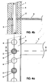
- the support arm 5 is integrally connected to the joint liner 1f. As can be seen from the illustration in FIG. 4 a, the support arm 5 projects at a right angle from the rear side of the plate-shaped ceramic body 1. In modified embodiments of the bearing arm may be formed projecting with angle deviating from 90 °.
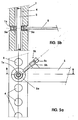
- FIGS. 5a and 5b show a modified support arm construction.
- the support arm 5 is also arranged there in the joint intermediate area. However, it is not integrally connected to the joint liner 1f, but formed as a separate arm 5, which is provided with a hook-shaped receptacle 5a at its end and engages in a receiving groove of a disc-shaped joint intermediate storage 1s this cross and a clamping screw connection 5k at the disc-shaped joint intermediate storage 1f is fixed.
- the clamping screw connection 5k consists of a clamping screw 5s, which is screwed into a fixedly connected to the support arm 5 threaded sleeve 5h and engages with its clamping screw end with tightened clamping screw 5s in the receiving groove of the joint intermediate bearing 1s clamping.
- the disc-shaped joint intermediate storage is 1s of an inner disc with a small diameter and composed of two axially outer discs of larger diameter.
- This disk device 1s is arranged in the joint area between the ceramic body modules 1m and is held firmly clamped in the clamped state by the ceramic body modules 1m.
- the disk device 1s has a central through-hole, which is penetrated by the bias tension rod 2 coaxial with game.
- the joint intermediate bearing 1s may also be designed without receiving groove, preferably as a cylindrical bearing body, in modified embodiments.
- Correspondingly constructed support arms 5 can also be arranged in the region of the front ends of the ceramic body 1 or for fastening e.g. engage the over the Vorspannwiderlager 3 outward ends of the Vorspannzugstäbe 2 and fixed there against rotation. Alternatively or additionally, however, the support arms 5 can also be attached directly to components of the Vorspannwiderlagers 3 or connected to these.
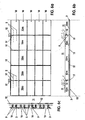
- a curtain ventilated facade wall is shown. It consists of prestressed ceramic facade panels 10 which are attached to a building wall 11 mounted substructure 12.
- the prestressed facade panels 10 correspond in their construction to the prestressed components illustrated in the figures described above.
- Each facade panel 10 in Fig. 6 consists of five braced together in the longitudinal direction successively arranged plate-shaped modules 10m, which are each constructed identically.
- Each of the composite facade panels 10 is penetrated in each case by two Vorspannzugsgliedem 2, which are biased on frontally supported abutment 3, so that the facade panels form prestressed components.
- two support arms 5 are provided in each case.
- the modules 10m also in the average and / or length design be different, preferably similar. They may, for example, also be profiled differently from the rectangular or round cross-sectional configuration.
- prestressed ceramic facade panels 20 are used in a building-side stationary support structure 22.
- This building-side support structure 22 consists of fixedly mounted vertical supports 22, on which the prestressed plate-shaped components 20 are pivotally mounted about a horizontal axis of rotation 20h.
- corresponding rotary bearings 22 are arranged on the vertical supports, in which the prestressed elements are mounted rotatably.
- the engaging in the pivot bearing journals can be formed by the projecting beyond the ends of the ends of Vorspannzugstäbe 2.
- corresponding separate bearing rods can be provided which can be arranged in the prestressed ceramic components, preferably the ceramic body 1, without bias.
- the pivotally mounted facade panels 20 form in the embodiment in Fig. 7 adjustable exposure and ventilation wings.
- prestressed ceramic components 30 which have a corresponding structure as the elements in the exemplary embodiments described above, are used in a staircase construction. They are supported in the region of their front ends in lateral steel cheeks 32, in that the front ends of the pretensioning tie rods 2 which engage through the pretensioning abutment 3 engage in bearings in the lateral steel cheeks 32.
- the illustrated construction forms a bridge with two steps 34 on both opposite sides and a connecting platform 35 connecting the two upper steps 34.
- the steps 34 on the two sides are each formed by three prestressed plate-shaped components 30 which are arranged in stages, the bridge pedestal is formed by the components forming the two uppermost stages and a further component 30 arranged between them.
- a railing 36 is arranged, which consists of three vertical steel beams 36v, at which vertically aligned a biased plate-shaped ceramic component 39, consisting of two plate-shaped modules 39m is arranged.
- This preloaded Component 39 is held above the vertical railing posts 36v by coupling the two outer posts 36v at the ends of the component 39 to the ends of the biasing tie rods projecting from the biasing pads 3 and connecting the center post 36v to the joint intermediate layer adjacent the joint is arranged between the plate-shaped modules 39m of the ceramic component.
- a handrail 36h is arranged which may be formed of a metal bar or the like.
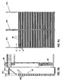
- the support structure 47 consists of vertical profiles 47v, which is suspended in front of the building wall 48 via support struts 47t.
- the vertical profiles 47v form a mounting plane that is vertically aligned at a distance in front of the vertical building wall 48.
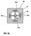
- the baguettes 40 correspond in their basic structure to the previously described prestressed plate-shaped ceramic bodies. They have a rod-shaped ceramic body 41. As shown in FIG. 9c, this body is designed as a hollow profile body with a central profile cavity 41h. The cross section of the profile body is square. The profile cavity also has a square basic shape, but in the opposite square sides in each case centrally, undercut recesses 41a are arranged, which are dovetail-shaped in cross section in the illustrated embodiment. These undercut recesses 41a are grooves which extend in the longitudinal direction of the profile in the opposite walls of the profile cavity. In the profile cavity, a bias tension member 42 is arranged, which is formed in the illustrated embodiment as a profile with cross-shaped profile cross-section.
- the mutually perpendicular profile legs are T-shaped at their free end in each case in cross section. These T-shaped ends in cross-section engage in the undercut grooves 41 a.
- the Vorspannzugelement 42 is supported with its front ends in on the end faces of the ceramic body 41 Clamped not shown Vorspannwiderlagern. You can be supported on the end faces of the ceramic body arranged there pressure-resistant end plates. By tightening the preload abutment, the biasing tension member 42 is biased to tension, biasing the ceramic body 41 under pressure. It is thereby formed the baguette 40 as a biased ceramic component.
- Baguettes are increased due to the bias in terms of their bending tensile values, so that they can withstand larger wind loads compared to conventional non-aforementioned baguettes and can be stored with larger spans.
- a break fall protection is obtained in case of breakage of the ceramic body. This means that in the case of fracture does not crash the entire ceramic body or all fragments, but the ceramic body is largely maintained even after a break on the entanglement of Vorspannzugglieds with the recesses of the ceramic body in the supporting structure.
- 42 obtained by the engagement of the radially projecting profile legs of the biasing tension elements a rotation of the ceramic body 41 in the mounting position.
- Fig. 10a ceramic body 101 which can be used to form a baguette-type prestressed ceramic component. They each have a profile cavity 101h, which extends axially in the longitudinal direction of the profile body and in which one or more biasing tension members, not shown, can be arranged.
- the outer cross section of the ceramic bodies 101 is different in the various embodiments, that is circular, square, triangular, oval, hexagonal, star-shaped, etc.
- the cross-section of the profile cavity 101h is also different in the embodiments, namely circular, square and triangular.
- a plurality of profile cavities 102h arranged parallel to one another in a plane are respectively formed, wherein in one or more of these profile cavities 102h bias tension elements can be arranged.
- profile cavities 102k with a smaller cross-section are present in this embodiment. These profile cavities are not provided for receiving Vorspannzugianon, but only for manufacturing reasons in conjunction with the drying and the firing process in the ceramic body available.
- the further embodiments shown in FIG. 10a are ceramic bodies 103 and 104. They each have a plurality of parallel profile cavities 103h and 104h, which are arranged in a plurality of mutually parallel planes or in mutually angularly arranged planes. Also in these profile cavities 103h and 104h bias tension elements can be introduced. In addition, in the Keramikkörpem 103, 104 and other profile cavities 103k 104k are provided with a smaller cross-section, which are not provided for receiving Vorspannzug instituten.
- the ceramic bodies 105, 106, 107 and 108 are hollow profile bodies with a square, round, triangular or oval outer cross section, each having a central profile cavity 105h, 106h, 107h, 108h with a large cross-sectional area. Further profile cavities with a smaller cross-sectional area are arranged coaxially around the central profile cavity in the profile body.
- Vorspannzugieri can be arranged in the central profile cavity. Additionally or alternatively, however, biasing tension elements can also be used in the outer profile cavities with a smaller cross section.
- the further variants shown in FIG. 10b are ceramic profile bodies 109, 110, 111, 112 which are wing-shaped or teardrop-shaped in cross-section and also have a plurality of profile cavities for receiving bias tension elements.
- the biasing tension element preferably as a separate component, engages through the anchor element.
- the anchor element is a e.g. tubular body which the biasing tension member has e.g. as a pull rod passes through.
Landscapes
- Engineering & Computer Science (AREA)
- Architecture (AREA)
- Structural Engineering (AREA)
- Civil Engineering (AREA)
- Chemical & Material Sciences (AREA)
- Ceramic Engineering (AREA)
- Dispersion Chemistry (AREA)
- Bridges Or Land Bridges (AREA)
- Building Environments (AREA)
Applications Claiming Priority (2)
| Application Number | Priority Date | Filing Date | Title |
|---|---|---|---|
| DE10253494 | 2002-11-16 | ||
| DE2002153494 DE10253494A1 (de) | 2002-11-16 | 2002-11-16 | Keramikelement zur Anordnung in einem Bauwerk |
Publications (2)
| Publication Number | Publication Date |
|---|---|
| EP1420124A1 EP1420124A1 (de) | 2004-05-19 |
| EP1420124B1 true EP1420124B1 (de) | 2007-03-07 |
Family
ID=32115551
Family Applications (1)
| Application Number | Title | Priority Date | Filing Date |
|---|---|---|---|
| EP20030025578 Expired - Lifetime EP1420124B1 (de) | 2002-11-16 | 2003-11-08 | Vorgehängte Fassadenkonstruktion mit Keramikbauelementen |
Country Status (3)
| Country | Link |
|---|---|
| EP (1) | EP1420124B1 (da) |
| DE (2) | DE10253494A1 (da) |
| DK (1) | DK1420124T3 (da) |
Cited By (1)
| Publication number | Priority date | Publication date | Assignee | Title |
|---|---|---|---|---|
| US10913243B2 (en) | 2016-01-19 | 2021-02-09 | Enclos Corporation | Pre-stressed plate or shell structures |
Families Citing this family (5)
| Publication number | Priority date | Publication date | Assignee | Title |
|---|---|---|---|---|
| FR2919319B1 (fr) * | 2007-07-25 | 2012-07-13 | Imerys Tc | Element de construction prefabrique |
| DE102012008948A1 (de) | 2012-05-05 | 2013-11-07 | Schunk Ingenieurkeramik Gmbh | Keramikbauelement |
| CN107217779B (zh) * | 2017-05-23 | 2019-08-16 | 黄俊强 | 一种陶板及其生产方法和应用幕墙 |
| WO2022150930A1 (en) * | 2021-01-17 | 2022-07-21 | 1284343 B.C. Ltd. | System and method for forming a wall |
| FR3157451B1 (fr) * | 2023-12-21 | 2026-03-13 | Neoclin Atlantic | Dispositif de ventilation de façade et dispositif de fabrication d’un lot pour un dispositif de ventilation |
Family Cites Families (8)
| Publication number | Priority date | Publication date | Assignee | Title |
|---|---|---|---|---|
| DE713211C (de) * | 1939-07-12 | 1941-11-03 | Wilhelm Allers | Bauteil, insbesondere Decke, Wand, Dach o. dgl. |
| FR990656A (fr) * | 1944-03-23 | 1951-09-25 | éléments de construction et leur dispositif de montage | |
| CH387261A (de) * | 1959-05-25 | 1965-01-31 | Inst Ziegelforschung Essen E V | Verfahren zur Herstellung von Bauteilen, wie z. B. Träger, Balken oder Stützen, aus einzelnen geformten Elementen |
| LU79400A1 (fr) * | 1978-04-07 | 1979-11-07 | Wildenberg S Van Den | Elements de construction en pierres naturelles ou composites armees et procede pour leur fabrication |
| US4294051A (en) * | 1979-05-21 | 1981-10-13 | Hughes Jr William J | Modular building system |
| FR2652845B1 (fr) * | 1989-10-05 | 1993-04-23 | Ivaldi Marc | Ensemble de construction. |
| DE29612473U1 (de) * | 1996-07-18 | 1996-10-17 | Aleksandrov, Garri, Dr., 19057 Schwerin | Sturzelement für ein Ziegelmauerwerk |
| US5860527A (en) * | 1996-10-18 | 1999-01-19 | Menasha Corporation | Plastic tote box improvements |
-
2002
- 2002-11-16 DE DE2002153494 patent/DE10253494A1/de not_active Ceased
-
2003
- 2003-11-08 DK DK03025578T patent/DK1420124T3/da active
- 2003-11-08 EP EP20030025578 patent/EP1420124B1/de not_active Expired - Lifetime
- 2003-11-08 DE DE50306735T patent/DE50306735D1/de not_active Expired - Fee Related
Cited By (2)
| Publication number | Priority date | Publication date | Assignee | Title |
|---|---|---|---|---|
| US10913243B2 (en) | 2016-01-19 | 2021-02-09 | Enclos Corporation | Pre-stressed plate or shell structures |
| US12403675B2 (en) | 2016-01-19 | 2025-09-02 | Enclos Corporation | Pre-stressed plate or shell structures |
Also Published As
| Publication number | Publication date |
|---|---|
| DK1420124T3 (da) | 2007-07-09 |
| EP1420124A1 (de) | 2004-05-19 |
| DE10253494A1 (de) | 2004-05-27 |
| DE50306735D1 (de) | 2007-04-19 |
Similar Documents
| Publication | Publication Date | Title |
|---|---|---|
| DE1807716A1 (de) | Vorgefertigtes,transportables Raumelement zur Herstellung von Bauwerken | |
| EP3269889B1 (de) | Verbindungssystem | |
| EP1883737A2 (de) | Wandaufbau bei einem gebäude | |
| AT403601B (de) | Pfostenträger, insbesondere für die holzstützen von balkonen, pergolen, carports, blockhäusern o.dgl. | |
| EP2886738B1 (de) | Fassadendämmsystem | |
| EP1420124B1 (de) | Vorgehängte Fassadenkonstruktion mit Keramikbauelementen | |
| DE3824387C2 (da) | ||
| DE19737515C2 (de) | Vorrichtung zur Befestigung von Bauteilen an und im Abstand zu einem Tragwerk, insbesondere von Längsprofilen an und im Abstand zu einer Bauwerkswand und dafür geeigneter Abstandhalter | |
| DE4300823A1 (de) | Gelaender zur Befestigung an seitlichen Begrenzungswänden | |
| DE1683121C3 (de) | Spindeltreppe | |
| DE202016007440U1 (de) | Porenbeton-Bauteil, Doppelwandelement und Wandbefestigungssystem auf Porenbetonbasis | |
| EP1420123B1 (de) | Keramikbauelement | |
| DE10321947B4 (de) | Verfahren zum Errichten eines Holzhauses oder dgl. Bauwerkes | |
| DE102011110920B4 (de) | Gebäude sowie Verfahren zu seiner Herstellung | |
| EP3333350B1 (de) | Beschlag zum sichern von fenster- und türrahmen an einer laibung und verfahren welches einen solchen beschlag verwendet | |
| DE7008866U (de) | Verankerung zur freihaengenden befestigung vorgefertigter wand- oder fassadenplatten. | |
| DE102020206226A1 (de) | Trägerelement und Verfahren zur Herstellung einer freikragenden Balkonanlage sowie Verwendung eines Trägerelements zur Herstellung einer freikragenden Balkonanlage | |
| DE19724393A1 (de) | Wandstützenbefestigung | |
| EP3428359B1 (de) | Befestigungswinkel für ein fassadendämmsystem und fassadendämmsystem mit einem solchen befestigungswinkel | |
| EP0360002B1 (de) | Unterbaukonstruktion für hinterlüftete Fassadenplatten | |
| DE804134C (de) | In Leichtbauweise hergestelltes Fachwerkhaus | |
| WO2008037404A1 (de) | Stahlbetonkonstruktion für ein gebäude und verfahren zur erstellung einer solchen konstruktion | |
| DE102025132360A1 (de) | Wangenfreie Treppe, insbesondere Kragarmtreppe, Befestigung einer Stufe an einer aufstrebenden Wand einer wangenfreien Treppe und Verfahren zur Herstellung einer wangenfreien Treppe, insbesondere Kragarmtreppe | |
| DE20318689U1 (de) | Holzbauelement | |
| DE2023618A1 (de) | Verankerung zur freihängenden Befestigung vorgefertigter Wand- oder Fassadenplatten |
Legal Events
| Date | Code | Title | Description |
|---|---|---|---|
| PUAI | Public reference made under article 153(3) epc to a published international application that has entered the european phase |
Free format text: ORIGINAL CODE: 0009012 |
|
| AK | Designated contracting states |
Kind code of ref document: A1 Designated state(s): AT BE BG CH CY CZ DE DK EE ES FI FR GB GR HU IE IT LI LU MC NL PT RO SE SI SK TR |
|
| AX | Request for extension of the european patent |
Extension state: AL LT LV MK |
|
| 17P | Request for examination filed |
Effective date: 20040915 |
|
| 17Q | First examination report despatched |
Effective date: 20041206 |
|
| AKX | Designation fees paid |
Designated state(s): DE DK GB NL |
|
| GRAP | Despatch of communication of intention to grant a patent |
Free format text: ORIGINAL CODE: EPIDOSNIGR1 |
|
| RTI1 | Title (correction) |
Free format text: CURTAIN WALL CONSTRUCTION WITH CERAMIC BUILDING ELEMENTS |
|
| GRAS | Grant fee paid |
Free format text: ORIGINAL CODE: EPIDOSNIGR3 |
|
| GRAA | (expected) grant |
Free format text: ORIGINAL CODE: 0009210 |
|
| AK | Designated contracting states |
Kind code of ref document: B1 Designated state(s): DE DK GB NL |
|
| REG | Reference to a national code |
Ref country code: GB Ref legal event code: FG4D Free format text: NOT ENGLISH |
|
| REF | Corresponds to: |
Ref document number: 50306735 Country of ref document: DE Date of ref document: 20070419 Kind code of ref document: P |
|
| GBT | Gb: translation of ep patent filed (gb section 77(6)(a)/1977) |
Effective date: 20070613 |
|
| REG | Reference to a national code |
Ref country code: DK Ref legal event code: T3 |
|
| PLBE | No opposition filed within time limit |
Free format text: ORIGINAL CODE: 0009261 |
|
| STAA | Information on the status of an ep patent application or granted ep patent |
Free format text: STATUS: NO OPPOSITION FILED WITHIN TIME LIMIT |
|
| PGFP | Annual fee paid to national office [announced via postgrant information from national office to epo] |
Ref country code: NL Payment date: 20071121 Year of fee payment: 5 Ref country code: DK Payment date: 20071128 Year of fee payment: 5 Ref country code: DE Payment date: 20071018 Year of fee payment: 5 |
|
| 26N | No opposition filed |
Effective date: 20071210 |
|
| PGFP | Annual fee paid to national office [announced via postgrant information from national office to epo] |
Ref country code: GB Payment date: 20071123 Year of fee payment: 5 |
|
| REG | Reference to a national code |
Ref country code: DK Ref legal event code: EBP |
|
| GBPC | Gb: european patent ceased through non-payment of renewal fee |
Effective date: 20081108 |
|
| PG25 | Lapsed in a contracting state [announced via postgrant information from national office to epo] |
Ref country code: NL Free format text: LAPSE BECAUSE OF NON-PAYMENT OF DUE FEES Effective date: 20090601 |
|
| NLV4 | Nl: lapsed or anulled due to non-payment of the annual fee |
Effective date: 20090601 |
|
| PG25 | Lapsed in a contracting state [announced via postgrant information from national office to epo] |
Ref country code: DK Free format text: LAPSE BECAUSE OF NON-PAYMENT OF DUE FEES Effective date: 20081130 Ref country code: DE Free format text: LAPSE BECAUSE OF NON-PAYMENT OF DUE FEES Effective date: 20090603 |
|
| PG25 | Lapsed in a contracting state [announced via postgrant information from national office to epo] |
Ref country code: GB Free format text: LAPSE BECAUSE OF NON-PAYMENT OF DUE FEES Effective date: 20081108 |