EP1419799B1 - Radiologisches behandlungsgerät - Google Patents
Radiologisches behandlungsgerät Download PDFInfo
- Publication number
- EP1419799B1 EP1419799B1 EP02765347A EP02765347A EP1419799B1 EP 1419799 B1 EP1419799 B1 EP 1419799B1 EP 02765347 A EP02765347 A EP 02765347A EP 02765347 A EP02765347 A EP 02765347A EP 1419799 B1 EP1419799 B1 EP 1419799B1
- Authority
- EP
- European Patent Office
- Prior art keywords
- head
- irradiation
- waveguide
- irradiation head
- radiotherapy apparatus
- Prior art date
- Legal status (The legal status is an assumption and is not a legal conclusion. Google has not performed a legal analysis and makes no representation as to the accuracy of the status listed.)
- Expired - Fee Related
Links
Images


Classifications
-
- A—HUMAN NECESSITIES
- A61—MEDICAL OR VETERINARY SCIENCE; HYGIENE
- A61N—ELECTROTHERAPY; MAGNETOTHERAPY; RADIATION THERAPY; ULTRASOUND THERAPY
- A61N5/00—Radiation therapy
- A61N5/10—X-ray therapy; Gamma-ray therapy; Particle-irradiation therapy
- A61N5/1048—Monitoring, verifying, controlling systems and methods
- A61N5/1049—Monitoring, verifying, controlling systems and methods for verifying the position of the patient with respect to the radiation beam
-
- A—HUMAN NECESSITIES
- A61—MEDICAL OR VETERINARY SCIENCE; HYGIENE
- A61N—ELECTROTHERAPY; MAGNETOTHERAPY; RADIATION THERAPY; ULTRASOUND THERAPY
- A61N5/00—Radiation therapy
- A61N5/10—X-ray therapy; Gamma-ray therapy; Particle-irradiation therapy
-
- A—HUMAN NECESSITIES
- A61—MEDICAL OR VETERINARY SCIENCE; HYGIENE
- A61N—ELECTROTHERAPY; MAGNETOTHERAPY; RADIATION THERAPY; ULTRASOUND THERAPY
- A61N5/00—Radiation therapy
- A61N5/10—X-ray therapy; Gamma-ray therapy; Particle-irradiation therapy
- A61N5/1077—Beam delivery systems
- A61N5/1081—Rotating beam systems with a specific mechanical construction, e.g. gantries
- A61N5/1082—Rotating beam systems with a specific mechanical construction, e.g. gantries having multiple beam rotation axes
-
- A—HUMAN NECESSITIES
- A61—MEDICAL OR VETERINARY SCIENCE; HYGIENE
- A61B—DIAGNOSIS; SURGERY; IDENTIFICATION
- A61B90/00—Instruments, implements or accessories specially adapted for surgery or diagnosis and not covered by any of the groups A61B1/00 - A61B50/00, e.g. for luxation treatment or for protecting wound edges
- A61B90/10—Instruments, implements or accessories specially adapted for surgery or diagnosis and not covered by any of the groups A61B1/00 - A61B50/00, e.g. for luxation treatment or for protecting wound edges for stereotaxic surgery, e.g. frame-based stereotaxis
- A61B2090/101—Instruments, implements or accessories specially adapted for surgery or diagnosis and not covered by any of the groups A61B1/00 - A61B50/00, e.g. for luxation treatment or for protecting wound edges for stereotaxic surgery, e.g. frame-based stereotaxis for stereotaxic radiosurgery
-
- A—HUMAN NECESSITIES
- A61—MEDICAL OR VETERINARY SCIENCE; HYGIENE
- A61N—ELECTROTHERAPY; MAGNETOTHERAPY; RADIATION THERAPY; ULTRASOUND THERAPY
- A61N5/00—Radiation therapy
- A61N5/10—X-ray therapy; Gamma-ray therapy; Particle-irradiation therapy
- A61N5/1048—Monitoring, verifying, controlling systems and methods
- A61N5/1049—Monitoring, verifying, controlling systems and methods for verifying the position of the patient with respect to the radiation beam
- A61N2005/1061—Monitoring, verifying, controlling systems and methods for verifying the position of the patient with respect to the radiation beam using an x-ray imaging system having a separate imaging source
-
- A—HUMAN NECESSITIES
- A61—MEDICAL OR VETERINARY SCIENCE; HYGIENE
- A61N—ELECTROTHERAPY; MAGNETOTHERAPY; RADIATION THERAPY; ULTRASOUND THERAPY
- A61N5/00—Radiation therapy
- A61N5/10—X-ray therapy; Gamma-ray therapy; Particle-irradiation therapy
- A61N5/103—Treatment planning systems
- A61N5/1037—Treatment planning systems taking into account the movement of the target, e.g. 4D-image based planning
Definitions
- the present invention relates to a radiotherapy apparatus suited to performing, e.g., radiotherapy on a tumor by a stereotactic pluridirectional irradiation method.
- a stereotactic pluridirectional irradiation method is one radiotherapy method capable of increasing the therapeutic effect by intensively irradiating a diseased part with radiation in multiple directions, and minimizing the exposure dose of the surrounding tissue of the diseased part.
- This stereotactic pluridirectional irradiation method is considered effective in curing diseased parts, such as a primary benign brain tumor, a simple metastatic brain tumor having a size of 3 cm or less, a small morbid part in the brain, e.g., skull base metastasis which is difficult to operate, arterial malformation, and venous malformation.
- an apparatus which performs irradiation after positioning an irradiation head with respect to a patient by using a positioning means is conventionally known. Since, however, a doctor or assistant does not confirm the position of a focus by directly viewing the irradiation field before irradiation, the accuracy of irradiation is not high.
- the present invention is a radiotherapy apparatus comprising:
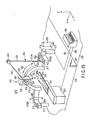
- a radiotherapy apparatus 6-1 includes a bed 7 having a top plate 8 on which a patient 4 is placed, an irradiation head 10 for irradiating an irradiation field 5 settable in the patient 4 with therapeutic radiation, and an X-ray CT apparatus 30 for acquiring a tomographic image of the irradiation field 5 as a diseased part.
- the top plate 8 can be moved in three axis directions, i.e., a bed longitudinal direction (X-axis direction), bed widthwise direction (Y-axis direction), and bed vertical direction (Z-axis direction), by an X-Y driving mechanism (not shown) contained in the bed 7. Also, the position of this top plate 8 is controlled by a computer system (not shown) on the basis of an image taken by a TV camera (not shown), so that the irradiation field 5 of the patient 4 is positioned in an isocenter 5a. Furthermore, the material and shape of the top plate 8 are so selected as to match the X-ray CT apparatus 30 as an image acquiring apparatus or a PET (Positron Emission Tomography) apparatus.
- X-axis direction bed longitudinal direction
- Y-axis direction bed widthwise direction
- Z-axis direction bed vertical direction
- the position of this top plate 8 is controlled by a computer system (not shown) on the basis of an image taken by a TV camera (not shown), so that the i
- Reference numeral 3b denotes image acquiring X-rays (image acquiring radiation) of the X-ray CT apparatus 30; and 20, an inclining mechanism for inclining the X-ray CT apparatus 30 in a direction K1 shown in FIG. 1 .
- the patient 4 is placed on the top plate 8 such that his or her body axis lies along the bed longitudinal direction.
- the X- and Y-axis directions are horizontal directions, and the Z-axis direction is a vertical direction.
- the irradiation head 10 is movably supported by a substantially semicircular arch-shaped guide rail 9 via a circumferential moving mechanism 68 and head rotating mechanism 69, and emits therapeutic radiation 3a.
- This irradiation head 10 is positioned in an arbitrary irradiation position within the range of a half sphere around the isocenter 5a by the circumferential moving mechanism 68 and head rotating mechanism 69.
- the circumferential moving mechanism 68 circumferentially moves (H1) the irradiation head 10 along the guide rail 9.
- a rack and pinion or belt can be used.
- the irradiation head 10 is also coupled with a fourth joint 16 of waveguide systems 11 and 15.
- the irradiation head 10 is, as shown in detail in FIG. 4 (to be described later), the irradiation head 10 is electromagnetically connected to a microwave oscillator 70 such as a klystron via waveguides 50, 51, and 52 forming the waveguide system 11.
- the head rotating mechanism 69 rotates (H2) the irradiation head 10 on the guide rail 9 around the fourth joint 16.
- the irradiation head 10 has a total length of 800 to 1,000 mm and an outer dimension of 300 to 500 mm.
- the guide rail 9 is a semicircular ring which forms the upper half of a circle above the top plate 8, and is formed across this top plate 8 in the widthwise direction.
- This guide rail 9 is movably supported by a tilting mechanism and a pair of cylinder mechanisms 28.
- the tilting mechanism tilts (G1) the guide rail 9 around a tilting axis 26 shown in FIG. 2 within the range of 0° to 180°, as shown in FIG. 1 .
- the guide rail 9 is made of a very rigid material such as stainless steel, and has a width of 200 to mm, a thickness of 20 to 50 mm, and a radius of 800 to 1,000 mm from the isocenter 5a.
- the pair of cylinder mechanisms 28 support the left and right lower end portions of the guide rail 9, and move this guide rail 9 up and down (G2) in the Z-axis direction.
- These cylinder mechanisms 28 are controlled by a computer 62 as a position control means, such that their operations are synchronized.
- the tilt (G1) of the guide rail 9 and the circumferential motion (H1) of the irradiation head 10 allow isocentric motion of the irradiation head 10 on a half sphere around the isocenter 5a.
- the vertical motion (G2) of the guide rail 9 and the rotation (H2) of the irradiation head 10 allow non-isocentric motion of the irradiation head 10 in a position deviated from the half sphere around the isocenter 5a.
- the X-ray CT apparatus 30 has a donut-like vacuum bath, and contains a large number of concentrically arranged X-ray generating units in this vacuum bath.
- the vacuum bath has a central opening, and this opening is used as a diagnostic space. That is, the patient 4 and the top plate 8 are taken in and out through this diagnostic space.
- the X-ray CT apparatus 30 of this embodiment is a nonmagnetic image acquiring apparatus.
- the X-ray CT apparatus 30 of this embodiment is a so-called fifth-generation apparatus in which an X-ray source and detector remain stationary, and this will be explained in more detail later.
- this X-ray CT apparatus 30 of this embodiment it is also possible to use a third-generation X-ray CT apparatus in which an X-ray source and detector rotate, or a fourth-generation X-ray CT apparatus in which an X-ray source rotates and a detector remains stationary.
- the X-ray CT apparatus 30 of this embodiment can be supported as it is inclined through, e.g., 20° to 30° to the Z axis by the image acquiring apparatus inclining mechanism 20 shown in FIG. 1 .
- this inclining mechanism 20 is driven, the X-ray CT apparatus 30 tilts (K1) to change the irradiation angle of the image acquiring X-ray 3b.
- the X-ray CT apparatus 30 and guide rail 9 are mechanically closely connected, and have a common coordinate reference.
- the X-ray CT apparatus 30 is so controlled that the guide rail 9 and irradiation head 10 do not interfere with each other.
- an X-ray fluoroscopic apparatus When an X-ray fluoroscopic apparatus is used in place of the X-ray CT apparatus 30 as an image acquiring apparatus, the resolution and contrast are lower than those of the X-ray CT apparatus 30. Therefore, a small gold plate, for example, is embedded near the irradiation field, and an image of this gold plate is taken into a fluoroscopic image. In this manner, high positional accuracy can be assured by using the plate image as a marker and marking the irradiation field on the basis of this marker.
- PET can also be used instead of the X-ray CT apparatus or X-ray fluoroscopic apparatus described above.
- an MRI apparatus can also be used as a magnetic image acquiring apparatus.
- SAD Source Axis Distance
- FIG. 1 the distance from the isocenter 5a to a target 110 ( FIG. 4 ) in the irradiation head 10.
- this SAD is set at 80 cm.
- joints 14a to 14c and the joint 16 of the waveguide system 11 contain a rotary RF coupler 50 for transmitting accelerating microwaves by axial rotation.
- the waveguides 51 and 52 are formed in the waveguide system 11. These waveguides 51 and 52 electromagnetically communicate with each other by the rotary RF coupler 50 in the joints 14a to 14c.
- the rotary RF coupler 50 is connected to the waveguides 51 and 52 by flange couplings 53 and 54, respectively.
- Reference numerals 55a and 55b denote waveguides of these waveguides 51 and 52.
- these waveguides 55a and 55b of the waveguides 51 and 52 communicate with a rotating space surrounded by rotating members 56 and 57 of the rotary RF coupler 50. Therefore, an electric field (vector or mode) is formed in this rotating space, and microwaves propagate.
- reference numeral 58 denotes a bearing; and 59, a ⁇ /4-wave choke.
- the waveguide system 11 is a link mechanism having one end fixed to the end portion of the guide rail 9 via the first joint 14a, and the other end connected to the irradiation head 10 via the fourth joint 16.
- Reference numeral 21 denotes a circulator; and 22, a dummy load.
- the waveguide system 11 is made up of the first joint 14a fixed to the end portion of the guide rail 9, a first waveguide 12 having one end rotatably connected to the first joint 14a, the second joint 14b to which the other end of the first waveguide 12 is connected, a second waveguide 13 having one end connected to the second joint 14b, the third joint 14c to which the other end of the second waveguide 13 is connected, a third waveguide 15 having one end connected to the third joint 14c, and the fourth joint 16 to which the other end of the third waveguide 15 is connected, and which is connected to the irradiation head 10.
- first joint 14a is formed along the Y axis, and the second to fourth joints 14b, 14c, and 16 are formed along the X axis.
- the X-ray CT apparatus 30 will be described in detail below.
- This X-ray CT apparatus 30 irradiates the irradiation field 5 of an object to be examined such as the patient 4 with the image acquiring X-rays 3b as fan-shaped X-rays in multiple directions, detects transmitted X-rays, and performs image processing for the detection data, thereby displaying a tomographic image of the irradiation field 5 on the computer screen.
- the X-ray CT apparatus 30 of this embodiment is a so-called fifth-generation apparatus including a donut-like vacuum bath (not shown) having a central opening as a diagnostic space.
- This vacuum bath is evacuated by a vacuum pump through an exhaust port.
- the vacuum bath contains a large number of X-ray generating units (not shown) arranged on the same circle near the outer circumference, and a large number of sensor arrays (not shown) arranged on the same circle near the inner circumference in one-to-one correspondence with the large number of X-ray generating units.
- These X-ray generating units and sensor arrays are shifted in the X-axis direction, so the image acquiring X-rays 3b are emitted in the form of a fan in a direction in which the X-rays 3b incline forward with respect to the radius of the vacuum bath. Accordingly, the fan-shaped image acquiring X-rays 3b are transmitted through the patient 4 in the diagnostic space without being interrupted by the sensor array on the X-ray irradiation side, and the transmitted X-rays can be detected by the sensor array on the opposite side.
- a beam limiter In addition, a beam limiter, electron gun driving circuit, image signal digitizer, and the like are arranged in the vacuum bath.
- the fan-shaped X-rays 3b emitted from the X-ray generating units are collimated by a collimator, and limited to the width at the irradiation position by the beam limiter.
- the sensor arrays are densely fixed on the circumference surrounding the diagnostic space, include a large number of ultra high sensitivity CdTe sensors, and have a resolution of 0.5 mm.
- the image sensing width of one shot during image acquisition is approximately 80 mm.
- the X-ray irradiation time is 0.01 sec for one shot.
- An X-ray generation controller (not shown) is connected to a data recorder (not shown), and receives an X-ray generation command signal from the computer 62.
- X-ray transmission data detected by the sensor arrays is converted into an electric current signal proportional to the transmitted X-ray amount, supplied to the digitizer (not shown) and the data recorder (not shown) via a preamplifier and main amplifier (neither is shown), and recorded.
- the data recording timing is controlled by the X-ray generation command signal from the computer 62.
- the recorded data is output from the data recorder to a signal processor (not shown), and processed by this signal processor.
- the processed data is displayed as a tomographic image of the irradiation field 5 on a display (not shown).
- the output terminal of the X-ray generation controller is connected to a power supply and anodes, cathodes, and gate array grid electrodes (none of them are shown) in the X-ray generating units.
- the X-ray generation controller controls the supply of power from the power supply (not shown) to the electron gun driving circuit (not shown), and selects a grid electrode suited to an image sensing portion from the gate array, on the basis of the command.
- an electron beam is emitted from a certain cathode in the X-ray generating units, a minus bias voltage applied to the selected grid electrode is released to zero potential, and the electron beam enters the anode through a hole in the grid electrode.
- the anode When the electron beam thus enters the anode, the anode generates secondary X-rays, so the fan-shaped image acquiring X-rays 3b are emitted toward the patient 4 through the collimator attached to the window.
- the computer 62 controls the driving of the circumferential moving mechanism 68, head rotating mechanism 69, and inclining mechanism 20 on the basis of the data, thereby finely adjusting the position and direction of the irradiation head 10 to allow this irradiation head 10 to aim at the irradiation field 5 in the isocenter 5a or non-isocenter 5b.
- the irradiation head 10 of this embodiment generates therapeutic radiation 3a by accelerating electrons to an energy of 4 to 20 MeV, and functions as a subminature electron linac irradiation head.
- the outside of this irradiation head 10 is covered with an outer case 101 which shields radiation.
- the irradiation head 10 has an electron gun 103, an accelerator 105, a focusing coil 109, the X-ray target 110, a flattening filter 112, and a focusing tube 113.
- the rear end of the outer case 101 is covered with an insulating cap 102.
- a cable 104 connected to a power supply 64 is introduced into the case 101 via this insulating cap 102, and connected to the electron gun 103.
- the output from the power supply 64 of the electron gun 103 is controlled by the computer 62.
- Components from the electron gun 103 to the flattening filter 112 are arranged in series along the central axis of an electron beam.
- the accelerator 105 follows the electron gun 103, and the focusing tube 113 follows the accelerator 105.
- the waveguide 51 communicates with the accelerator 105.
- This waveguide 51 also communicates with the microwave oscillator 70 and a vacuum pump 71. Therefore, the accelerator 105 is evacuated by the pump 71 through the waveguide 51.
- a ceramic window 72 is fitted in the main path of the waveguide 51, that branches and communicates with the vacuum pump 71. This ceramic window 72 prevents leakage of SF 6 gas sealed in a waveguide from the microwave oscillator 70 to the ceramic window 72, and passes only microwaves.
- the microwave oscillator 70 is a klystron type oscillator superior in output stability.
- a power supply circuit of this microwave oscillator 70 is connected to the computer 62.
- the electron gun 103 has a filament (cathode) formed in a chamber evacuated by the vacuum pump 71.
- the accelerator 105 follows and communicates with the chamber in which the electron gum 103 is accommodated, and accelerates an output electron beam from this electron gun 103.
- the interior of this accelerator 105 is divided by a plurality of partitions 106 to form a plurality of acceleration chambers 107.
- An electron beam passing hole 106a is formed in the center of the partition 106.
- a coil 108 is wound around the outer surface of each acceleration chamber 107, and connected to a power supply circuit whose operation is controlled by the computer 62.
- the focusing tube 113 follows the accelerator 105. To this focusing tube 113, the focusing coil 109, X-ray target 110, and flattening coil 112 are attached in this order. The focusing coil 109 focuses the electrons accelerated by the accelerator 105 toward the X-ray target 110.
- the X-ray target 110 receives high-energy accelerated electrons and outputs bremsstrahlung X-rays. Therefore, a water cooling jacket 111 having a flow path 111a is attached to this X-ray target 110 to forcedly cool it in order to prevent thermal damage.
- this target 110 it is preferable to use a metal such as tungsten, molybdenum, or tantalum, or an alloy of any of these metals.
- the flattening filter 112 is made of a metal, and forms the therapeutic radiation 3a having a substantially uniform energy density by averaging the intensities of X-rays emitted from the target 110.
- a collimator 114 and dose measurement tube 120 are attached to the outside of the outer case 101.
- the collimator 114 is screwed into the distal end of the outer case 101, and has a hollow portion which communicates with the focusing tube 113.
- This collimator 114 is made of a highly shielding material, such as lead, through which the therapeutic radiation 3a cannot pass.
- the X-rays 3a are supplied to the dose measurement tube 120 through the hollow portion.
- the dose measurement tube 120 is an ionization chamber in which a gas is sealed. This dose measurement tube 120 detects the charge amount of ionized gas generated when radiation passes by, and measures the dose of the radiation.
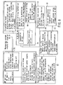
- the radiotherapy apparatus of this embodiment has a control system including the therapeutic bed system 7 and 8, the irradiation head 10, the X-ray CT apparatus 30, a signal processor 31, the microwave oscillator 70, a system controller 80, and a system utility 90.
- the system controller 80 controls the whole system.
- This system controller 80 includes a system control calculator, system management algorithm, image tracking algorithm, therapy plan algorithm, therapy management algorithm, graphical user interface, therapy database, interlock algorithm, and system monitor.
- the system controller 80 comprehensively controls the entire control system, and exchanges input and output signals with other blocks.
- the X-ray CT apparatus 30 is connected to the system controller 80 via the signal processor 31. During radiotherapy, therefore, the X-ray CT apparatus 30 acquires images in real time, so a doctor can perform the therapy while monitoring the images on the display.
- the microwave oscillator 70 comprises a klystron modulator and linac system controller, a klystron, and an RF driver.
- the klystron as a source for supplying microwaves to the accelerator 110 is connected to the irradiation head 10 via the waveguide system 11.
- the isocentric driving mechanism and head rotating mechanism of the irradiation head 10 are connected to the system controller 80 to control circumferential motion driving of the irradiation head 10 during isocentric irradiation and biaxial head rotation driving of the irradiation head 10 during pseudo non-isocentric irradiation.
- a doctor makes a therapy plan.
- This therapy plan is based on various examinations performed before the operation.
- the doctor directly acquires images of a diseased part in real time by using the radiotherapy apparatus of this embodiment. By this image acquisition, high-accuracy, high-reliability radiotherapy can be performed.
- an image of the irradiation field 5 and its nearby region is acquired by using only the X-ray CT apparatus 30.
- a doctor checks each sectional view of the irradiation field 5 on the system screen, and defines a contour for image tracking. Mapping of the irradiation field 5 is complete before the start of therapy, so the contour of the irradiation field 5 is defined by a plurality of slices on the basis of this mapping.
- the contour of an image of the actual irradiation field 5 is extracted by the image tracking system of the radiotherapy apparatus.
- Image tracking is started by pattern matching between this extracted contour and the defined contour. The doctor visually checks the status of this image tracking.
- the doctor operates a master arm SW to set the system in an armed state.
- the system displays the target by cross hair lines on the image, and also displays the irradiation volume in red on the same image. Since the image tracking continues, the target and irradiation volume automatically follow the movement of the irradiation field.
- irradiation of the therapeutic radiation 3a is started by a trigger operation by the doctor. Since a scheduled irradiation time is determined in the stage of the therapy plan, countdown is started on the screen, and the therapeutic radiation is automatically stopped when the count is zero (time t4). A dose distribution is continuously displayed on the screen, so the doctor keeps pulling the trigger to continue the irradiation while checking this displayed dose distribution.
- the system alternatively continues image sampling and irradiation of the therapeutic radiation 3a at high speed, thereby continuing image tracking and therapeutic beam irradiation in real time. Even before the countdown becomes zero, if the doctor releases the trigger the therapeutic radiation 3a immediately stops at that timing, to maintain safety.
- the doctor puts the master arm SW in the safe position to set the system in the safe state, and moves the irradiation head 10 to the next irradiation position.
- the doctor checks the total dose which is the total of the accumulated exposure doses.
- the accumulated dose and the accumulate dose distribution in one course are displayed on the screen and stored in a therapy file formed for each patient.
- the conditions such as the irradiation position and irradiation time can be controlled with high accuracy while the irradiation field is monitored by the X-ray CT apparatus 30. Accordingly, the embodiment is not only applicable to a therapy of the head in which no organ moves, but also a small focus of an organ which moves, such as a heart or lung, can be accurately irradiated. Therefore, this technology is expected to have wide applications in the field of radiotherapy.
- this embodiment can use a high-strength, high-rigidity irradiation head supporting structure, as opposed to a cantilevered robot arm, which has rigidity having many problems. This makes it possible to mechanically ensure high absolute accuracy. This obviates the need for teaching required to assure necessary positioning accuracy by using a robot arm, and allows an efficient therapy.
- a doctor cannot monitor the irradiation field in real time during radiotherapy, so irradiation based upon presumption is unavoidable.
- a doctor can monitor the irradiation field in real time during radiotherapy by using the image acquiring apparatus such as an X-ray fluoroscopic apparatus, X-ray CT apparatus, PET, or DSA. This allows highly reliable and safe radiotherapy. Also, on the basis of the image of the irradiation field obtained in real time as described above, it is possible to track the image, and follow and irradiate the moving irradiation field.
- the radiotherapy apparatus of this embodiment achieves a man-machine interface with a doctor. Accordingly, radiotherapy superior in safety and reliability can be performed.
- FIGS. 10 to 25 A radiotherapy apparatus 6-2 of the second embodiment of the present invention will be described below with reference to FIGS. 10 to 25 in which the same reference numerals as in FIGS. 1 to 9 denote the same parts.
- FIGS. 10 to 12 correspond to FIGS. 1 to 3
- FIG. 18 corresponds to FIG. 8
- FIGS. 21 and 22 correspond to FIGS. 5 and 6
- FIG. 25 corresponds to FIG. 9 . Therefore, a repetitive explanation of the same portions will be omitted.
- an irradiation head 1000 of this embodiment is supported by a guide rail 9 by a circumferential moving mechanism 68 and first and second head rotating mechanisms 1310 and 1320.
- These circumferential moving mechanism 68 and first and second head rotating mechanisms 1310 and 1320 position the irradiation head 1000 in an arbitrary irradiation position within the range of a quarter sphere (half sphere) of the rear portion of the upper half of a sphere around an isocenter 5a.
- the circumferential moving mechanism 68 circumferentially moves (H1) the irradiation head 1000 along the guide rail 9 by, e.g., a rack and pinion system or belt system.
- the first head rotating mechanism 1310 includes a servo motor, and rotates the irradiation head 1000 on the guide rail 9 around a first axis S1 of a rotary RF coupler 16.
- This rotary RF coupler 16 is placed on an axis substantially passing through the center of inertia of the irradiation head 1000, so that the inertial force decreases when the irradiation head 1000 rotates.
- the second head rotating mechanism 1320 includes a servo motor, and rotates the irradiation head 1000 on the guide rail 9 around a second axis S2 of rotary RF couplers 500A and 500B.
- These rotary RF couplers 500A and 500B placed on an axis substantially passing through the center of inertia of the irradiation head 1000, so that the inertial force decreases when the irradiation head 1000 rotates.
- the irradiation head 1000 of this embodiment has a total length of 500 to 600 mm, width 500 mm X depth 300 mm, and a weight of 60 to 80 kg.
- This irradiation head 1000 is rotatably coupled with the rotary RF coupler 16 of a waveguide system 11.
- the irradiation head 1000 is connected to a microwave oscillator 70 by waveguides 510 and rotary RF couplers 500 on a gimbal mechanism shown in FIG. 20A .
- Biaxial driving G1 and H1 described above permits isocentric motion of the irradiation head 1000 on the half sphere around the isocenter 5a.
- biaxial driving S1 and S2 described above permits pseudo non-isocentric motion of the irradiation head 1000 on the half sphere.
- This pseudo non-isocentric motion is the rotation of the irradiation head 1000 around the center of inertia, and hence is much faster than the isocentric motion.
- This pseudo-isocentric, high-response, rapid tracking motion allows the head to follow and aim at even a rapid motion such as heartbeat with high response and high precision.
- a microdisplacement angle ⁇ 1 around the head rotation driving axis S1 and a microdisplacement angle ⁇ 2 around the head rotation driving axis S2 are calculated by shift amounts DV1 and DV2 obtained from image data and predetermined expressions.
- driving of the head rotating mechanisms 1310 and 1320 is controlled to rotate the irradiation head 1000 through the microdisplacement angles ⁇ 1 and ⁇ 2 at high speed.
- the irradiation head 1000 can follow and aim, at high speed and high response, at a diseased part 5 below the neck, e.g., a tumor having a motion such as breathing, heartbeat, peristalsis, or the urine amount in a bladder. This realizes high-accuracy irradiation.
- the irradiation head 1000 can be rotated at high speed within 0.1 sec including the acquired image processing time. This allows the irradiation head 1000 to rapidly follow the movement of the irradiation field (diseased part).
- waveguides 550a and 550b of the waveguide 510 communicate with a rotating space surrounded by rotary members 560 and 570 of the rotary RF coupler 500. In this rotating space, microwaves are guided in a waveguide mode as shown in FIG. 23B .
- a system controller 80 controls driving of the circumferential moving mechanism 68, a tilting mechanism, and a bed 7 on the basis of this data, thereby aiming the irradiation head 1000 at the irradiation field 5 in the isocenter 5a.
- the system controller 80 performs calculations for image tracking on the basis of input data from the X-ray CT apparatus 30. On the basis of the calculation results, the system controller 80 controls the operations of the first and second head rotating mechanisms 1310 and 1320, thereby rotating the irradiation head 1000. While the irradiation head 1000 is rotated, an interlock operates to inhibit irradiation. This minimizes the exposure dose in a nearby portion.
- a main body of this irradiation head 1000 is covered with a cover 1010, and an emitting portion 1200 for emitting radiation is attached to the front end of this head main body.
- the cover 1010 for covering the head main body contains an electric circuit/cooling water circuit 1160, an accelerator 1100, an RF window 520, the waveguide 510, the part 500B of the rotary RF coupler, an exhaust pipe 1070, an ion pump 1120, a target exhaust chamber 1190, a target 1210, and a cooling plate 1220.
- a cable (not shown) connected to an external power supply is introduced into the cover 1010 from an insulator 1030 at the rear end of the accelerator 1100, and connected to a cathode 1050 of an electron gun 1040.
- An anode 1060 faces this cathode 1050.
- a portion between the cathode 1050 and anode 1060 is exhausted by the exhaust pipe 1070 which communicates with the ion pump 1120.
- a power supply of the electron gun 1040 is controlled by the system controller 80.
- the electron gun 1040 continues from the accelerator 1100 to the emitting portion 1200.
- the length from the insulator 1030 to the front end of the accelerator 1100 is about 360 mm.
- a central hole in the anode 1060 of the electron gun 1040 communicates with a buncher cavity 1090 of the accelerator 1100.
- the accelerator 1100 accelerates an electron beam emitted from the electron gun 1040, and collides the high-energy electron beam against the X-ray target 1210.
- an acceleration cavity 1110b having a central hole for passing the electron beam is formed.
- This acceleration cavity 1110b communicates with a pair of left and right side exhaust pipes 1080 via side couple cavities 1110a.
- the pair of left and right side exhaust pipes 1080 are connected to the ion pump 1120. Accordingly, the pair of left and right side exhaust pipes 1080 are evacuated by the ion pump 1120. That is, the accelerator 1100 is evacuated by the ion pump 1120 via the side couple cavities 1110a and side exhaust pipes 1080.
- the waveguide 510 communicates with the accelerator 1100.
- This waveguide 510 communicates with the microwave oscillator 70 via the ceramic RF window 520 and rotary RF couplers 500A and 500B.
- the RF window 520 prevents leakage of SF 6 gas sealed in the waveguide 510, and functions as an entrance for introducing microwaves into the accelerator 1100.
- the microwave oscillator 70 is a klystron type oscillator superior in output stability. A power supply circuit of this microwave oscillator 70 is connected to the system controller 80.
- the emitting portion 1200 is formed at the end portion of the head main body covered with the cover 1010, and includes the X-ray target 1210, the target cooling plate 1220, a primary collimator 1230, and a flattening filter 1240. Components from the electron gun 1040 to the flattening filter 1240 via the accelerator 1100 are arranged in series along the optical axis of the electron beam. The accelerated electron beam is incident on the target 1210 of the emitting portion 1200 through the target exhaust chamber 1190.
- the X-ray target 1210 receives high-energy accelerated electrons and outputs bremsstrahlung X-rays. Therefore, this X-ray target 1210 is readily damaged by heat. As a countermeasure against this heat, the cooling plate 1220 cools the X-ray target 1210. As this target 1210, a refractory metal such as tungsten, molybdenum, or tantalum, or an alloy of any of these metals is used.
- the primary collimator 1230 is made of a material, such as tungsten, which is superior in shielding properties against radiation and generates few thermal neutrons. This primary collimator 1230 guides X-rays from the target 1210 to the flattening filter 1240.
- the flattening filter 1240 forms therapeutic radiation 3a having a uniform dose distribution by averaging the intensities of X-rays emitted from the target 1210.
- a secondary collimator 1250 and dose measurement ionization chamber 1260 are attached to the front end of the emitting portion 1200.
- the secondary collimator 1250 is made of a highly shielding material, such as tungsten, through which the therapeutic radiation 3a cannot pass, and supplies the therapeutic radiation 3a to the dose measurement ionization chamber 1260 through a hollow portion.
- This secondary collimator 1250 is detachably screwed into the end face of the primary collimator 1230.
- the dose measurement ionization chamber 1260 is an ionization chamber which is attached to the end portion of the secondary collimator 1250, and in which a gas having a predetermined component is sealed.
- a detection circuit (not shown) for detecting discharged electric charge is connected to this dose measurement ionization chamber 1260. This detection circuit is connected to the input of the system controller 80.
- the system controller 80 calculates the dose of the therapeutic radiation emitted from the irradiation head 1000, and saves the calculated dose in a memory as dose data of a therapy which a patient 4 undergoes.
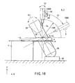
- a control system of the radiotherapy apparatus of this embodiment will be described below with reference to FIG. 18 .
- the control system of the apparatus of this embodiment includes a bed 8, the irradiation head 1000, the X-ray CT apparatus 30, a signal processor 31, the microwave oscillator 70, the system controller 80, and a system utility 90.
- the system controller 80 controls the whole system.
- This system controller 80 includes a system control calculator, system management algorithm, image tracking algorithm, therapy plan algorithm, therapy management algorithm, graphical user interface, therapy database, interlock algorithm, and system monitor.
- the X-ray CT apparatus 30 is connected to the system controller 80 via the signal processor 31. Accordingly, images are acquired in real time during a therapy, so a doctor can perform the therapy while monitoring the acquired images on the display.
- the microwave oscillator 70 comprises a klystron modulator and linac system controller, a klystron, and an RF driver.
- the klystron which supplies microwaves to the accelerator 1100 is connected to the irradiation head 1000 via the waveguide system 11.
- the isocentric driving mechanism and head rotating mechanisms of the irradiation head 1000 are connected to the system controller 80.
- the circumferential moving mechanism 68 is controlled during isocentric irradiation, and the biaxial head rotating mechanisms 1310 and 1320 are controlled during pseudo non-isocentric irradiation.
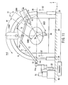
- the irradiation head 1000 of this embodiment is supported by a gimbal structure support frame 1020 of the head cover 1010.
- This support frame 1020 is positioned at coordinates where the axes S1 and S2 including the center of inertia of the irradiation head 1000 pass by.
- the rotary RF coupler 16 of the waveguide system 11, the pair of rotary RF couplers 500A and 500B, the S1 head rotating mechanism 1310 which is a servo motor, and the S2 head rotating mechanism 1320 which is also a servo motor are attached to the four sides of the support frame 1020.
- the rotary RF coupler 16 of the waveguide system 11 is attached to the center of one long side of the support frame 1020.
- a driving shaft 1310a of the S1 head rotating mechanism 1310 is attached to the center of the opposite long side of the frame 1020 so as to face the rotary RF coupler 16.
- this driving shaft 1310a is rotated, as shown in FIG. 17 , the irradiation head 1000 rotates around the driving axis S1.
- the pair of rotary RF couplers 500A and 500B are attached to the center of one short side of the support frame 1020.
- a driving shaft 1320a of the S2 head rotating mechanism 1320 is attached to the center of the opposite short side of the frame 1020 so as to face the pair of rotary RF couplers 500A and 500B. That is, the main body of the S2 head rotating mechanism 1320 is fixed to a bracket 1020a of the support frame 1020, and the driving shaft 1320a is rotatably supported by the support frame 1020 via a bearing 1330.
- this driving shaft 1320a is rotated, as shown in FIG. 16 , the irradiation head 1000 rotates around the driving axis S2.
- the waveguides 510 are formed in link arms 13 and 15 of the waveguide system 11.
- the rotary RF couplers 500 are formed in joints 14 and 16. Microwaves are introduced into the accelerator 1100 in the irradiation head through the pair of rotary RF couplers 500A and 500B.
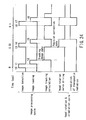
- the operation of the radiotherapy apparatus 6-2 of this embodiment particularly, a method of preventing the influence which direct rays, leakage rays, and scattered rays of therapeutic radiation have on a detector, thereby realizing real-time, time-divisional processing of irradiation of image acquiring X-rays and irradiation of therapeutic radiation, will be explained below with reference to a timing chart shown in FIG. 24 .
- the power supplies of the therapeutic bed system 7, irradiation head 1000, X-ray CT apparatus 30, microwave oscillator 70, system controller 80, and system utility 90 are set in a standby state.
- the top plate 7 moves to move the patient 4 into a therapy area. More specifically, the diseased part 5 is aligned with the isocenter 5a by moving the X-ray CT apparatus 30 and/or the bed 8. After this isocentric alignment is completed, real-time image acquisition by the X-ray CT apparatus 30 and radiotherapy by the irradiation head 1000 are started.
- the X-ray CT apparatus 30 starts irradiating the irradiation field 5 with image acquiring X-rays 3b.
- the fluoroscopic image is detected as an acquired image at time t0 to time t1 shown in FIG. 24 .
- the irradiation time of the image acquiring X-rays 3b is also limited between time t0 and time t1.
- the irradiation head 1000 is interlocked so as not to emit the therapeutic radiation 3a.
- the detected acquired image is loaded (recorded) at time t1 to time t2.
- information such as tracking image data of the loaded acquired image is processed by the signal processor 31 and system controller 80, and the processed image is displayed on the display. Also, the information processed by this image tracking calculation is supplied as position correction data to the head rotating mechanisms 1310 and 1320. The same cycle from image acquisition to image processing as in time t0 to time t3 is repeated after time t3.
- the head rotating servos of the head rotating mechanisms 1310 and 1320 are driven through the micro-head-rotating angles ⁇ 1 and ⁇ 2 on the basis of the result of the image tracking calculation supplied as the position correction data.
- the irradiation head 1000 is interlocked so as not to emit therapeutic radiation 3a.
- the irradiation head 1000 is released from interlocking and starts emitting the therapeutic radiation 3a.
- the irradiation time of the therapeutic radiation 3a is time t5 to time t6 before the head rotating mechanisms 1310 and 1320 are driven next.
- an image tracking calculation is executed for the tracking image data of the image acquired between time t3 and t5.
- third image detection and second head rotating servo driving are started, and the second image tracking calculation and the first irradiation of the therapeutic radiation 3a are complete.
- irradiation of the image acquiring X-rays 3b is started at time t6 to proceed to the next acquired image processing cycle beginning from time t6.
- the irradiation head 1000 is released from interlocking, and the second irradiation of the therapeutic radiation 3a is restarted.
- the image processing cycle and the head rotating and irradiation cycle overlap each other. While a certain image processing cycle is performed, a cycle of head rotational driving and irradiation of the therapeutic radiation 3a is performed on the basis of information of an image processing cycle executed immediately before this image processing cycle.
- one standard of time t0 to time t6 from the start of image detection to the end of irradiation of the therapeutic radiation 3a via rotation of the irradiation head 1000 is 0.1 sec or less.
- one cycle of image processing and one cycle of head rotation and irradiation are 0.05 sec. Accordingly, the times in the timing chart shown in FIG. 24 are merely examples, so the operation can also be carried out at other time intervals.
- the radiotherapy apparatus 6-2 of this embodiment is so designed as to emit the therapeutic radiation 3a after it is confirmed that rotation and positioning of the irradiation head 1000 are normally executed.
- the image detection cycle, the image loading cycle, the image tracking calculation cycle, the head rotation control cycle based on the image tracking calculation cycle, and the therapeutic radiation 3a emission cycle are repeated, and a therapy is performed by following and irradiating the irradiation field 5 from the position of the half sphere over the bed.
- FIG. 25 A therapeutic method of the radiotherapy apparatus 6-2 of this embodiment described above is shown in (a) to (e) of FIG. 25 . Since FIG. 25 is the same as FIG. 9 , a detailed explanation thereof will be omitted.
- the radiotherapy apparatus 6-2 of this embodiment described above it is possible to rapidly rotate the irradiation head 1000 within 0.1 sec including the image processing time, and allow the irradiation head 1000 to follow the movement of the irradiation field (diseased part). Accordingly, high-accuracy irradiation can be realized.
- an object to be cured can be a portion below the neck, where an object of irradiation such as a tumor moves under the influence of the motion and state of an organ, e.g., breathing, heartbeat, peristalsis, or the urine amount in a bladder.
- FIGS. 26 and 27 A radiotherapy apparatus according to the third embodiment of the present invention will be described below with reference to FIGS. 26 and 27 .
- FIGS. 26 and 27 a repetitive explanation of the same portions as in the previous figures will be omitted.
- an irradiation head 1000 In a radiotherapy apparatus 6-3 of this embodiment, an irradiation head 1000, an image acquiring X-ray source 97 as an X-ray tube of an X-ray CT apparatus, and a sensor array 98 are mounted on a rotary drum 9.
- the irradiation head 1000 is mounted on a drum of, e.g., a third-generation X-ray CT apparatus.
- the rotational center of the rotary drum 99 is an isocenter 5a.
- the irradiation head 1000 is equivalent to an electron linac which generates a radiation of 4 to 10 MeV. As shown in FIGS. 26 and 27 , this irradiation head 1000 has head rotating mechanisms having two axes (S1 and S2).
- Head rotation around the axis S2 must include aiming angle correction corresponding to rotation of the rotary drum 9. However, no aiming angle correction is necessary for head rotation around the axis S1.
- the image acquiring X-ray source 97 and sensor array 98 are attached to predetermined portions on the rotary drum 9 so as not to interfere with the irradiation head 1000. These image acquiring X-ray source 97 and sensor array 98 oppose each other.
- the sensor array 98 is a multi-row type sensor.
- FIG. 28 A radiotherapy apparatus according to the fourth embodiment of the present invention will be described below with reference to FIG. 28 .
- FIG. 28 a repetitive explanation of the same portions as in the previous figures will be omitted.
- an irradiation head 1000, X-ray sources 97A and 97B, and sensor arrays 98A and 98B are mounted on a rotary drum 99.
- a set of the X-ray source 97A and sensor array 98A and a set of the X-ray source 97B and sensor array 98B function as X-ray fluoroscopic devices.
- the viewing lines of these two X-ray fluoroscopic devices are different. Therefore, an X-ray fluoroscopic image containing an image of a landmark or a marker such as a gold microplate in the body of a patient 4 can be acquired in two axial directions. In this way, the movement of the patient's position can be known.
- image processing such as DSA can be performed by using a contrast medium.
- the irradiation head 1000 is the same as in the third embodiment.
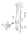
- a radiotherapy apparatus according to the fifth embodiment of the present invention will be described below with reference to FIGS. 29 to 37 .
- the radiotherapy apparatus of this embodiment comprises elements installed in a therapy room 200, and an element installed in an operation room 202 isolated from the therapy room 200 by a partition 201.
- the elements installed in the therapy room 200 are a supporting moving mechanism 210, an irradiation head 220 which is supported and moved on predetermined first spherical coordinates by the supporting moving mechanism 210, a microwave oscillator 230, a fixed waveguide unit 240, moving waveguide unit 250, and intra-head waveguide unit 260 which form a microwave transmission system for transmitting microwave power generated by the microwave oscillator 230 to a therapeutic radiation generator 221 in the irradiation head 220, and a bed 270.
- the element installed in the operation room 202 is a system console 280.
- the supporting moving mechanism 210 includes a pair of bases 211 and 212 fixed on the floor of the therapy room 200, a pair of tilting mechanisms 213 and 214 formed on the pair of bases 211 and 212, respectively, a guide rail 215 having a semicircular track for supporting and moving the irradiation head 220, and a pair of weights 216 and 217. That is, a track 215A is formed in the middle of the guide rail 215, and two end portions 215B1 and 215B2 of this guide rail 215 are supported by the tilting mechanisms 213 and 214 formed on the bases 211 and 212, respectively. By driving the tilting mechanisms 213 and 214, the guide rail 215 is rotated around an isocenter 300 in a direction indicated by reference numeral 301.
- the irradiation head 200 has the therapeutic radiation generator 221 including an electron gun, accelerator, target, collimator, vacuum pump, and the like, a circumferential moving mechanism 222 which circumferentially moves the irradiation head 220 along the track 215A in a direction indicated by reference numeral 302 by a mechanism such as a rack and pinion or a belt and pulley, and a gimbal mechanism 223 which rotates the therapeutic radiation generator 221 in two orthogonal directions indicated by reference numeral 303.
- the operations of the tilting mechanisms 213 and 214 and circumferential moving mechanism 222 allow isocentric rotation of the irradiation head 220. Also, the operation of the gimbal mechanism 223 (to be described later) permits pseudo non-isocentric rotation of the irradiation head 220.
- the microwave oscillator 230 is a microwave electron tube such as a klystron.
- This microwave oscillator 230, the microwave transmission system, and the therapeutic radiation generator 221 are integrally incorporated into a gantry including an irradiation head as a rotary member in a conventional radiotherapy apparatus such as a small electron linac.
- a lightweight irradiation head is realized by installing the heavy microwave oscillator 230 on the floor of the therapy room 200.
- the irradiation head 220 can be moved to an arbitrary position on the spherical coordinate system defined in the space of the therapy room 200.
- the moving waveguide unit 250 is a pantograph mechanism including first and second linear waveguides 251 and 252, and first, second, and third rotary couplers 253, 254, and 255.
- This moving waveguide unit 250 couples the fixed waveguide unit 240 and intra-head waveguide unit 260. That is, of the first, second, and third rotary RF couplers 253, 254, and 255 of the same type, the second rotary RF coupler 254 will be explained as a representative together with the first and second linear waveguides 251 and 252 with reference to FIG. 30 .
- the second rotary RF coupler 254 includes a first cylindrical member 254A to one end of which the first linear waveguide 251 is connected, and a second cylindrical member 254B which has the same axis as the first cylindrical member 254A, one end of which is rotatably connected to the other end of the first cylindrical member 254A via a bearing 254C, and to the other end of which the second linear waveguide 252 is connected.
- the axial direction of the first and second cylindrical members 254A and 254B is perpendicular to the extending direction of the first and second linear waveguides 251 and 252.
- a band filter plate 254D having two holes is formed in the opening of the first and second cylindrical members 254A and 254B.
- a magnetic sealing mechanism 254E is formed between the first and second cylindrical members 254A and 254B.
- This magnetic sealing mechanism 254E is used instead of an O-ring for airtight seal, and has a structure in which a magnetic fluid 254E3 is sandwiched between a pair of electromagnets 254E1 and 254E2.
- This magnetic sealing mechanism 254E formed between the first and second cylindrical members 254A and 254B is more advantageous in maintenance than a conventional O-ring which requires periodic replacement resulting from deterioration.
- microwave power transmitted in the extending direction of the first linear waveguide 251 is bent at a right angle at the entrance of the second rotary RF coupler 254, bent at a right angle again at its exit, and transmitted in the extending direction of the second linear waveguide 252.
- the first and second cylindrical members 254A and 254B of the second rotary RF coupler 254 can rotate. Therefore, the first and second linear waveguides 251 and 252 connected at right angles to the first and second cylindrical members 254A and 254B, respectively, can be rotated in different directions.
- one end of the first linear waveguide 251 having the other end connected to the second rotary RF coupler 254 is connected to the first rotary RF coupler 253 which has the same structure as the second rotary RF coupler 254 and is fixed to the end portion of the guide rail 215, and one end of the second linear waveguide 252 having the other end connected to the second rotary RF coupler 254 is connected to the third rotary RF coupler 255 which has the same structure as the second rotary RF coupler 254 and is fixed to the irradiation head 220.
- the first and second cylindrical members 254A and 254B of each of the first, second, and third rotary RF couplers 253, 254, and 255 rotate, so the first and second linear waveguides 251 and 252 can be opened and closed around the second rotary RF coupler 254.
- the moving waveguide unit 250 including the first and second linear waveguides 251 and 252 and the first, second, and third rotary RF couplers 253, 254, and 255 is a pantograph mechanism.
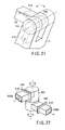
- FIG. 31 shows an example in which a bent transmission path is formed using two rotary RF couplers 254 and 254' and five waveguides.
- the rotary RF coupler 254 and linear waveguides 256 and 257 similar to those shown in FIG. 30 and the rotary RF coupler 254' and linear waveguides 256' and 257' analogous to those described above are coupled by a bent waveguide 258.
- a bent transmission path can be easily formed by manufacturing a plurality of sets of rotary RF couplers 254 shown in FIG. 30 and waveguides, and coupling these sets by bent waveguides.
- the irradiation head 220 can be moved to a given position on the spherical coordinate system defined in the space of the therapy room 200 by the supporting moving mechanism 210. Referring to FIG. 32 , this spherical coordinate system can be indicated by P1(r1, ⁇ 1, ⁇ 1). r1 is the distance between the isocenter 300 and the target.
- the third rotary RF coupler 255 of the moving waveguide unit 250 is moved on a spherical coordinate system indicated by P2(r2, ⁇ 2, ⁇ 2) in relation to the former coordinate system.
- r2 is the distance between the isocenter 300 and the axis of the third rotary RF coupler 255.
- the moving waveguide unit 250 can be moved on the spherical coordinate system P2 in accordance with the spherical coordinate system P1 on which the irradiation head 220 moves. This makes the movement of the moving waveguide unit 250 follow the movement of the irradiation head 220.
- this fixed waveguide unit 240 includes waveguides similar to the linear waveguides used in the moving waveguide unit 250, an E-bent waveguide 243 having flanges 241 and 242 at the two ends as shown in FIG. 33 , an H-bent waveguide 245 having flanges 244 and 245 at the two ends as shown in FIG. 34 , and rotary RF couplers analogous to the rotary RF couplers 253, 254, and 255 used in the moving waveguide unit 250, and couples the microwave oscillator 230 and the moving waveguide unit 250.
- the fixed waveguide unit 240 is connected from the output end of the microwave oscillator 230 to the first rotary RF coupler 253 formed in the end portion 215B2 of the guide rail 215 through the base 212.
- the irradiation head 220 and the intra-head waveguide unit 260 will be described below with reference to FIGS. 35A and 35B .
- the irradiation head 220 has the therapeutic radiation generator 221, circumferential moving mechanism 222, and gimbal mechanism 223, and also includes the intra-head waveguide unit 260.
- the circumferential moving mechanism 222 is not shown in FIGS. 35A and 35B .
- Servo mechanisms 223B and 223C for rotating the head in two orthogonal directions are attached to a frame 223A of the gimbal mechanism 223, thereby rotating the whole frame 223A in a position determined by the circumferential moving mechanism.
- an electron gun 221A an accelerator 221B such as a C-band standing-wave linear accelerator, a target 221C, a collimator 221D, and a vacuum pump 221E coupled with the accelerator 221B are mounted.
- an accelerator 221B such as a C-band standing-wave linear accelerator
- a target 221C a target 221C
- a collimator 221D a vacuum pump 221E coupled with the accelerator 221B
- an electron beam emitted from the electron gun 221A is accelerated by the accelerator 221B, and radiation is generated by colliding the accelerated electron beam against the target 221C.
- This radiation is shaped by the collimator 221D, and the patient (not shown) is irradiated with the therapeutic radiation from the irradiation head 220.
- the intra-head waveguide unit 260 is connected to the accelerator 221B in the above arrangement.
- This intra-head waveguide unit 260 has a rotary RF coupler 261 which incorporates an RF window 262, and one end of which is connected to the accelerator 221B.
- the other end of this rotary RF coupler 261 is connected to a bent waveguide 263.
- the rotary RF coupler 261 incorporating the RF window 262 and the bent waveguide 263 are mounted on the frame 223A of the gimbal mechanism 223.
- the circumferential moving mechanism has waveguides 265, 266, and 267, and the waveguide 267 is connected to the third rotary RF coupler 255 of the moving waveguide unit 250.
- the bent waveguide 263 mounted on the frame 223A of the gimbal mechanism 223 and the waveguide 265 of the circumferential moving mechanism are coupled by a flexible waveguide 264 having flanges 264A and 264B illustrated in detail in FIG. 36 .
- a flange 268 shown in FIG. 37 can be used as the flanges shown in FIGS. 33, 34 , and 36 .
- the bed 270 shown in FIG. 29 has a top plate 271 which moves in at least one of the Z direction (vertical direction) and X and Y directions (horizontal directions) while a patient 272 is placed on this top plate 271.
- the top plate 271 is moved by a moving mechanism (not shown) of the bed 270.
- the system console 280 shown in FIG. 29 automatically or manually controls the tilting mechanisms 213 and 214, the therapeutic radiation generator 221, circumferential moving mechanism 222, and gimbal mechanism 223 of the irradiation head 220, the microwave oscillator 230, and the bed 270.
- the radiotherapy apparatus of this embodiment constructed as above has the following effects. That is, the lightweight irradiation head 220 is realized by installing the heavy microwave oscillator 230 on the floor of the therapy room 200. Also, the combination of this irradiation head 220 and the characteristic supporting moving mechanism 210 permits the irradiation head 220 to move to an arbitrary position on the spherical coordinate system P1 defined in the space of the therapy room 200.
- the moving waveguide unit 250 can be moved on the spherical coordinate system P2 in accordance with the spherical coordinate system P1 on which the irradiation head 220 moves. This makes the movement of the moving waveguide unit 250 follow the movement of the irradiation head 220. Accordingly, microwave power can be easily supplied to the irradiation head 220 in a given position.
- the moving waveguide unit 250 forms a pantograph mechanism by the first and second linear waveguides 251 and 252, and the first, second, and third rotary RF couplers 253, 254, and 255. Therefore, the first and second linear waveguides 251 and 252 can be readily opened and closed around the second rotary RF coupler 254, and the moving amount can be absorbed. This makes it possible to prevent interference with the patient 272.
- the fixed waveguide unit 240 and intra-head waveguide unit 260 are formed using the E-bent waveguide 243, the H-bent waveguide 245, and rotary RF couplers similar to the rotary RF couplers 253, 254, and 255, in addition to linear waveguides.
- a bent transmission path can be formed in the minimum distance. This contributes to downsizing.
- the magnetic sealing mechanism 254E is formed between the first and second cylindrical members 254A and 254B of the rotary RF coupler 254. Accordingly, the generation of leaks caused by wear can be suppressed compared to the conventional O-ring, and the cycle of replacement by deterioration can be extended.
- the bent waveguide 263 mounted on the gimbal mechanism 223 of the intra-head waveguide unit 260 is coupled with the waveguide 265 of the circumferential moving mechanism by the flexible waveguide 264. Therefore, even when the therapeutic radiation generator 221 including the bent waveguide 263 causes a slight angular displacement by head rotation by the gimbal mechanism 223, this positional deviation of the therapeutic radiation generator 221 caused by the head rotation can be easily absorbed by the flexible waveguide 264. This allows smooth pseudo non-isocentric rotation of the irradiation head 220 by the gimbal mechanism 223, while predetermined microwave power is supplied to the therapeutic radiation generator 221.
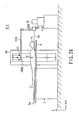
- FIGS. 38 and 39 A radiotherapy apparatus according to the sixth embodiment of the present invention will be described below with reference to FIGS. 38 and 39 .
- the same reference numerals as in FIGS. 29 to 37 denote the same parts, and an explanation thereof will be omitted.
- this radiotherapy apparatus has an arrangement in which a pair of tilting mechanisms 213 and 214 of a supporting moving mechanism 210 are arranged on a ceiling 203 and floor 204 of a therapy room 200.
- first and second linear waveguides 251 and 252 of the moving waveguide unit 250 are opened and closed between the ceiling 203 and floor 204. Therefore, an irradiation head 220 can be retracted from a patient 272 toward the ceiling 203. This reduces interference with and a sense of oppression on the patient.
- a fixed waveguide unit 240 can be arranged along the ceiling 203 and a wall or embedded in the ceiling 203 and the wall. This makes it possible to further utilize the therapy room 200 for therapy, and prevent collisions against doctors, technicians, and nurses. This also improves the therapeutic efficiency.
- image acquiring apparatuses such as an X-ray CT apparatus or MRI apparatus in the first to fourth embodiments can be combined, and the irradiation field can be positioned by an acquired diseased part image as in the first to fourth embodiments.
- the radiotherapy apparatus and the image acquiring apparatus can be interlocked by the console 280.
- the present invention can provide a radiotherapy apparatus having high therapeutic performance.
Landscapes
- Health & Medical Sciences (AREA)
- Engineering & Computer Science (AREA)
- Biomedical Technology (AREA)
- Veterinary Medicine (AREA)
- Nuclear Medicine, Radiotherapy & Molecular Imaging (AREA)
- Radiology & Medical Imaging (AREA)
- Life Sciences & Earth Sciences (AREA)
- Animal Behavior & Ethology (AREA)
- General Health & Medical Sciences (AREA)
- Public Health (AREA)
- Pathology (AREA)
- Radiation-Therapy Devices (AREA)
- Particle Accelerators (AREA)
- Physical Or Chemical Processes And Apparatus (AREA)
- Apparatus For Disinfection Or Sterilisation (AREA)
- Polarising Elements (AREA)
- Liquid Crystal (AREA)
- Medicines That Contain Protein Lipid Enzymes And Other Medicines (AREA)
- Soft Magnetic Materials (AREA)
- Pharmaceuticals Containing Other Organic And Inorganic Compounds (AREA)
- Feeding, Discharge, Calcimining, Fusing, And Gas-Generation Devices (AREA)
- Massaging Devices (AREA)
- Electrical Discharge Machining, Electrochemical Machining, And Combined Machining (AREA)
Claims (12)
- Eine Radiotherapievorrichtung umfassend:einen Bestrahlungskopf (10), der einen Linearbeschleuniger und eine kopfinterne Wellenleitereinheit aufweist, deren einer Endabschnitt elektromagnetisch mit dem Linearbeschleuniger verbunden ist;einen tragenden Bewegungsmechanismus (69), der den Bestrahlungskopf trägt und auf festgelegten ersten Kugelkoordinaten bewegt;einen Mikrowellenoszillator (70), der Mikrowellen erzeugt, die zum Bestrahlungskopf geleitet werden und der an einer stationären Position angeordnet ist;dadurch gekennzeichnet, dass sie umfassteine feststehende Wellenleitereinheit (51), aufweisend einen Endabschnitt, der elektromagnetisch mit dem Mikrowellenoszillator verbunden ist und der andere Endabschnitt an dem tragenden Bewegungsmechanismus angeordnet ist; undeine bewegte Wellenleitereinheit (52), aufweisend einen Endabschnitt, der elektromagnetisch mit dem anderen Endabschnitt der feststehenden Wellenleitereinheit verbunden ist, angeordnet auf dem tragenden Bewegungsmechanismus und der andere Endabschnitt elektromagnetisch mit dem anderen Endabschnitt der kopfinternen Wellenleitereinheit verbunden ist.
- Eine Radiotherapievorrichtung gemäß Anspruch 1, wobei die bewegte Wellenleitereinheit Mittel umfasst, die sich auf zweiten Kugelkoordinaten bewegen, die in Beziehung zu den ersten Kugelkoordinaten stehen.
- Eine Radiotherapievorrichtung gemäß Anspruch 1, wobei die kopfinterne Wellenleitereinheit, feststehende Wellenleitereinheit und bewegte Wellenleitereinheit einen Wellenleiter und einen drehenden RF-Koppler aufweisen.
- Eine Radiotherapievorrichtung gemäß Anspruch 1, wobei die bewegte Wellenleitereinheit einen Pantographenmechanismus umfasst, einen Wellenleiter und einen drehenden RF-Koppler beinhaltend, die sich im Zusammenspiel mit der Bewegung des Bestrahlungskopfes öffnen und schließen.
- Eine Radiotherapievorrichtung gemäß Anspruch 4, wobei der Pantographenmechanismus Mittel umfasst, die in einer Richtung schließen, abgewandt von einem mit therapeutischer Bestrahlung von dem Bestrahlungskopf zu bestrahlenden Patienten.
- Eine Radiotherapievorrichtung gemäß Anspruch 5, wobei die feststehende Wellenleitereinheit entlang der Decke und Wand eines Therapiezimmers angeordnet ist.
- Eine Radiotherapievorrichtung gemäß Anspruch 1, wobei mindestens eine der kopfinternen Wellenleitereinheit und feststehenden Wellenleitereinheit einen gekrümmten Wellenleiter aufweist.
- Eine Radiotherapievorrichtung gemäß Anspruch 1, wobei mindestens eine der kopfinternen Wellenleitereinheit und feststehenden Wellenleitereinheit einen flexiblen Wellenleiter aufweist.
- Eine Radiotherapievorrichtung gemäß Anspruch 3, wobei der drehende RF-Koppler ein erstes zylindrisches Element beinhaltet, ein Ende aufweisend, welches mit einem Wellenleiter verbunden ist, und ein zweites zylindrisches Element, dass dieselbe Achse wie das erste zylindrische Element hat, ein Ende davon drehbar mit dem anderen Ende des ersten zylindrischen Elements verbunden ist, und mit dem anderen Ende mit dem ein weiterer Wellenleiter verbunden ist.
- Eine Radiotherapievorrichtung gemäß Anspruch 3, wobei der drehbare RF-Koppler eine Magnetdichtung beinhaltet, die von einem internen Vakuum und abgedichteten Gas mindestens eines abdichtet.
- Eine Radiotherapievorrichtung gemäß Anspruch 1, wobei der Bestrahlungskopf einen Gimbalmechanismus umfasst, der den Bestrahlungskopf in mindestens zwei senkrechten Richtungen dreht.
- Eine Radiotherapievorrichtung gemäß Anspruch 1, weiterhin umfassend:einen isozentrischen Rotationsmechanismus, der den Bestrahlungskopf um ein Isozentrum dreht; undeinen pseudo nicht-isozentrischen Drehmechanismus, der den Bestrahlungskopf in eine Position dreht, wobei der Bestrahlungskopf durch den isozentrischen Rotationsmechanismus um einen festgelegten Winkel rotiert wird.
Applications Claiming Priority (5)
| Application Number | Priority Date | Filing Date | Title |
|---|---|---|---|
| JP2001254892 | 2001-08-24 | ||
| JP2001254891 | 2001-08-24 | ||
| JP2001254892 | 2001-08-24 | ||
| JP2001254891 | 2001-08-24 | ||
| PCT/JP2002/008505 WO2003018131A1 (fr) | 2001-08-24 | 2002-08-23 | Appareil de traitement radiologique |
Publications (3)
| Publication Number | Publication Date |
|---|---|
| EP1419799A1 EP1419799A1 (de) | 2004-05-19 |
| EP1419799A4 EP1419799A4 (de) | 2006-02-01 |
| EP1419799B1 true EP1419799B1 (de) | 2011-01-05 |
Family
ID=26620959
Family Applications (2)
| Application Number | Title | Priority Date | Filing Date |
|---|---|---|---|
| EP02760726A Expired - Lifetime EP1419800B1 (de) | 2001-08-24 | 2002-08-23 | Radiotherapie-gerät |
| EP02765347A Expired - Fee Related EP1419799B1 (de) | 2001-08-24 | 2002-08-23 | Radiologisches behandlungsgerät |
Family Applications Before (1)
| Application Number | Title | Priority Date | Filing Date |
|---|---|---|---|
| EP02760726A Expired - Lifetime EP1419800B1 (de) | 2001-08-24 | 2002-08-23 | Radiotherapie-gerät |
Country Status (8)
| Country | Link |
|---|---|
| US (2) | US7085347B2 (de) |
| EP (2) | EP1419800B1 (de) |
| JP (2) | JPWO2003018131A1 (de) |
| AT (1) | ATE384552T1 (de) |
| CA (2) | CA2427541C (de) |
| DE (2) | DE60238842D1 (de) |
| DK (2) | DK1419799T3 (de) |
| WO (2) | WO2003018133A1 (de) |
Cited By (1)
| Publication number | Priority date | Publication date | Assignee | Title |
|---|---|---|---|---|
| US8917813B2 (en) | 2010-02-24 | 2014-12-23 | Accuray Incorporated | Gantry image guided radiotherapy system and related treatment delivery methods |
Families Citing this family (137)
| Publication number | Priority date | Publication date | Assignee | Title |
|---|---|---|---|---|
| ES2283624T3 (es) | 2001-10-30 | 2007-11-01 | Loma Linda University Medical Center | Dispositivo para alinear a un paciente para la administracion de radioterapia. |
| US9682253B2 (en) * | 2002-06-05 | 2017-06-20 | Varian Medical Systems, Inc. | Integrated radiation therapy systems and methods for treating a target in a patient |
| US7251522B2 (en) * | 2002-09-12 | 2007-07-31 | Brainlab Ag | X-ray image-assisted navigation using original, two-dimensional x-ray images |
| US6889695B2 (en) * | 2003-01-08 | 2005-05-10 | Cyberheart, Inc. | Method for non-invasive heart treatment |
| EP1479411B2 (de) * | 2003-05-21 | 2012-01-18 | Varian Medical Systems Particle Therapy GmbH | Vorrichtung zur überwachten Tumorbestrahlung |
| CA2891712A1 (en) * | 2003-08-12 | 2005-03-03 | Loma Linda University Medical Center | Patient positioning system for radiation therapy system |
| DE10337803A1 (de) * | 2003-08-14 | 2005-03-17 | Eisenmann Lacktechnik KG (Komplementär: Eisenmann Stiftung) | Vorrichtung zum Behandeln der Oberfläche von Werkstücken, insbesondere von Fahrzeugkarosserien |
| WO2005024669A1 (en) * | 2003-09-04 | 2005-03-17 | Oracle International Corporation | Self-managing database architecture |
| GB0324676D0 (en) * | 2003-10-23 | 2003-11-26 | Elekta Ab | Apparatus for treatment by ionising radiation |
| US7295648B2 (en) | 2003-10-23 | 2007-11-13 | Elektra Ab (Publ) | Method and apparatus for treatment by ionizing radiation |
| US7710051B2 (en) * | 2004-01-15 | 2010-05-04 | Lawrence Livermore National Security, Llc | Compact accelerator for medical therapy |
| US20050175148A1 (en) * | 2004-02-10 | 2005-08-11 | Smither Robert K. | High Spatial Resolution X-ray and Gamma Ray Imaging System Using Crystal Diffraction Lenses |
| US20050267457A1 (en) * | 2004-05-25 | 2005-12-01 | Hruschka James A | Tissue ablation device using a lens to three dimensionally focus electromagnetic energy |
| US20050267359A1 (en) * | 2004-05-27 | 2005-12-01 | General Electric Company | System, method, and article of manufacture for guiding an end effector to a target position within a person |
| US7073508B2 (en) | 2004-06-25 | 2006-07-11 | Loma Linda University Medical Center | Method and device for registration and immobilization |
| DE102004062473B4 (de) * | 2004-09-30 | 2006-11-30 | Siemens Ag | Medizinische Strahlentherapieanordnung |
| CN104258506B (zh) * | 2005-02-04 | 2018-09-18 | 株式会社日立制作所 | 粒子射线照射方法及使用该方法的粒子射线照射装置 |
| DE102005013042A1 (de) * | 2005-03-18 | 2006-09-28 | Siemens Ag | Einrichtung zur Erzeugung von 3D-Fluoreszenz-oder Lumineszenz-Scans |
| US7561727B2 (en) * | 2005-06-02 | 2009-07-14 | Nordic Bioscience Imaging A/S | Method of deriving a quantitative measure of a degree of calcification of an aorta |
| US7463758B2 (en) * | 2005-06-02 | 2008-12-09 | Nordio Bioscience A/S | Method of deriving a quantitative measure of a degree of calcification of an aorta |
| US20070016014A1 (en) * | 2005-06-15 | 2007-01-18 | Kenji Hara | Radio therapy apparatus and operating method of the same |
| EP1749550A1 (de) * | 2005-08-04 | 2007-02-07 | Institut Curie | Verfahren und Gerät für Strahlentherapie |
| DE102005041122B3 (de) * | 2005-08-30 | 2007-05-31 | Siemens Ag | Gantry-System für eine Partikeltherapieanlage, Partikeltherapieanlage und Bestrahlungsverfahren für eine Partikeltherapieanlage mit einem derartigen Gantry-System |
| JP4713282B2 (ja) * | 2005-09-01 | 2011-06-29 | 株式会社日立製作所 | 放射線治療装置 |
| US7400700B2 (en) * | 2006-04-04 | 2008-07-15 | Brainlab Ag | Non-diagnostic stereoscopic x-ray tracking of moving objects in the context of radiotherapy and radiosurgery, with time-offset image recording |
| EP1842487B1 (de) * | 2006-04-04 | 2009-08-19 | BrainLAB AG | Stereoskopische Röntgenverfolgung bewegter Objekte im Rahmen der Radiotherapie und Radiochirurgie |
| US8983024B2 (en) | 2006-04-14 | 2015-03-17 | William Beaumont Hospital | Tetrahedron beam computed tomography with multiple detectors and/or source arrays |
| US9339243B2 (en) | 2006-04-14 | 2016-05-17 | William Beaumont Hospital | Image guided radiotherapy with dual source and dual detector arrays tetrahedron beam computed tomography |
| JP5538880B2 (ja) | 2006-04-14 | 2014-07-02 | ウィリアム・ボーモント・ホスピタル | 4面体ビームコンピュータ断層撮影 |
| US9192786B2 (en) * | 2006-05-25 | 2015-11-24 | William Beaumont Hospital | Real-time, on-line and offline treatment dose tracking and feedback process for volumetric image guided adaptive radiotherapy |
| US7535991B2 (en) | 2006-10-16 | 2009-05-19 | Oraya Therapeutics, Inc. | Portable orthovoltage radiotherapy |
| US7620147B2 (en) | 2006-12-13 | 2009-11-17 | Oraya Therapeutics, Inc. | Orthovoltage radiotherapy |
| EP1916015B1 (de) * | 2006-10-24 | 2011-06-08 | Pompilio Gatto | Gerät zur intraoperativen Strahlungstherapie mit Wellenleiter mit zweifacher Drehkupplung |
| JP2008173182A (ja) * | 2007-01-16 | 2008-07-31 | Mitsubishi Heavy Ind Ltd | 放射線照射方法および放射線治療装置制御装置 |
| ATE481132T1 (de) | 2007-01-16 | 2010-10-15 | Mitsubishi Heavy Ind Ltd | Strahlentherapiesystem zur durchführung einer strahlentherapie mit präziser bestrahlung |
| DE102008007245B4 (de) * | 2007-02-28 | 2010-10-14 | Siemens Aktiengesellschaft | Kombiniertes Strahlentherapie- und Magnetresonanzgerät |
| US8487269B2 (en) * | 2007-02-28 | 2013-07-16 | Siemens Aktiengesellschaft | Combined radiation therapy and magnetic resonance unit |
| US8363783B2 (en) | 2007-06-04 | 2013-01-29 | Oraya Therapeutics, Inc. | Method and device for ocular alignment and coupling of ocular structures |
| US8512236B2 (en) | 2008-01-11 | 2013-08-20 | Oraya Therapeutics, Inc. | System and method for positioning and stabilizing an eye |
| US8093572B2 (en) * | 2007-06-29 | 2012-01-10 | Accuray Incorporated | Integrated variable-aperture collimator and fixed-aperture collimator |
| US7848488B2 (en) * | 2007-09-10 | 2010-12-07 | Varian Medical Systems, Inc. | Radiation systems having tiltable gantry |
| US8337382B2 (en) * | 2007-11-01 | 2012-12-25 | John R. Adler, Jr. | Radiosurgical neuromodulation devices, systems, and methods for treatment of behavioral disorders by external application of ionizing radiation |
| US20090121155A1 (en) * | 2007-11-09 | 2009-05-14 | Elekta Ab (Publ) | Radiotherapy apparatus and parts thereof |
| WO2009072124A1 (en) * | 2007-12-05 | 2009-06-11 | Navotek Medical Ltd. | Detecting photons in the presence of a pulsed radiation beam |
| CN101951990A (zh) | 2007-12-23 | 2011-01-19 | Oraya治疗公司 | 检测、控制和预测辐射传输的方法和装置 |
| US7801271B2 (en) | 2007-12-23 | 2010-09-21 | Oraya Therapeutics, Inc. | Methods and devices for orthovoltage ocular radiotherapy and treatment planning |
| US7686511B2 (en) * | 2008-03-06 | 2010-03-30 | Moshe Ein-Gal | Angular irradiation in an upright treatment system |
| US8017915B2 (en) | 2008-03-14 | 2011-09-13 | Reflexion Medical, Inc. | Method and apparatus for emission guided radiation therapy |
| US7835494B2 (en) * | 2008-08-28 | 2010-11-16 | Varian Medical Systems International Ag | Trajectory optimization method |
| US8588369B2 (en) | 2008-08-28 | 2013-11-19 | Varian Medical Systems, Inc. | Radiation system with rotating patient support |
| US8215837B2 (en) * | 2008-09-03 | 2012-07-10 | Fluke Corporation | Integrated patient positioning and radiation quality assurance system and method |
| US7940891B2 (en) * | 2008-10-22 | 2011-05-10 | Varian Medical Systems, Inc. | Methods and systems for treating breast cancer using external beam radiation |
| US8180020B2 (en) | 2008-10-23 | 2012-05-15 | Accuray Incorporated | Sequential optimizations for treatment planning |
| DE102008057975A1 (de) | 2008-11-19 | 2010-05-20 | Rohde & Schwarz Gmbh & Co. Kg | Vorrichtung und Verfahren zur Positionierung bei Strahlungsbehandlungen |
| JP5604306B2 (ja) * | 2008-11-21 | 2014-10-08 | 国立大学法人東北大学 | 信号処理装置、信号処理方法、信号処理プログラム及び信号処理プログラムを記録したコンピュータ読み取り可能な記録媒体並びに放射線治療装置 |
| US8602647B2 (en) * | 2008-12-03 | 2013-12-10 | Daniel Navarro | Radiation beam analyzer and method |
| US8632448B1 (en) | 2009-02-05 | 2014-01-21 | Loma Linda University Medical Center | Proton scattering analysis system |
| JP5329256B2 (ja) * | 2009-02-19 | 2013-10-30 | 株式会社日立製作所 | ベッド位置決めシステム、放射線治療システム及びベッド位置決め方法 |
| DE102009013644A1 (de) * | 2009-03-17 | 2010-06-24 | Siemens Aktiengesellschaft | Strahlentherapieanlage mit Haltevorrichtung und Verfahren zur Bewegung eines Therapiestrahlauslassmoduls |
| CA2785995A1 (en) | 2010-01-05 | 2011-07-14 | William Beaumont Hospital | Intensity modulated arc therapy with continuous couch rotation/shift and simultaneous cone beam imaging |
| US8311187B2 (en) | 2010-01-29 | 2012-11-13 | Accuray, Inc. | Magnetron powered linear accelerator for interleaved multi-energy operation |
| AU2011215659B2 (en) | 2010-02-12 | 2013-10-17 | Loma Linda University Medical Center | Systems and methodologies for proton computed tomography |
| DE102010009019B4 (de) * | 2010-02-24 | 2012-04-19 | Siemens Aktiengesellschaft | Medizinisches, mit Röntgenstrahlen arbeitendes Gerät sowie Verfahren zum Betreiben eines solchen |
| US9687200B2 (en) | 2010-06-08 | 2017-06-27 | Accuray Incorporated | Radiation treatment delivery system with translatable ring gantry |
| US8284898B2 (en) * | 2010-03-05 | 2012-10-09 | Accuray, Inc. | Interleaving multi-energy X-ray energy operation of a standing wave linear accelerator |
| US8213571B2 (en) * | 2010-03-29 | 2012-07-03 | The Boeing Company | Small diameter X-ray tube |
| US8559596B2 (en) | 2010-06-08 | 2013-10-15 | Accuray Incorporated | Target Tracking for image-guided radiation treatment |
| WO2012008274A1 (ja) * | 2010-07-15 | 2012-01-19 | 三菱電機株式会社 | 粒子線照射装置およびこれを備えた粒子線治療装置 |
| WO2012010215A1 (en) * | 2010-07-23 | 2012-01-26 | Brainlab Ag | Non-planar treatment beam control |
| US8989846B2 (en) | 2010-08-08 | 2015-03-24 | Accuray Incorporated | Radiation treatment delivery system with outwardly movable radiation treatment head extending from ring gantry |
| US9324468B2 (en) | 2010-08-23 | 2016-04-26 | Varian Medical Systems, Inc. | Multileaf collimators with transverse motion |
| US9258876B2 (en) | 2010-10-01 | 2016-02-09 | Accuray, Inc. | Traveling wave linear accelerator based x-ray source using pulse width to modulate pulse-to-pulse dosage |
| US20130225974A1 (en) * | 2010-11-09 | 2013-08-29 | Koninklijke Philips Electronics N.V. | Magnetic resonance imaging system and radiotherapy apparatus with an adjustable axis of rotation |
| US8536547B2 (en) | 2011-01-20 | 2013-09-17 | Accuray Incorporated | Ring gantry radiation treatment delivery system with dynamically controllable inward extension of treatment head |
| US8873710B2 (en) | 2011-03-07 | 2014-10-28 | Sloan-Kettering Institute For Cancer Research | Multi-source radiation system and method for interwoven radiotherapy and imaging |
| JP5952844B2 (ja) | 2011-03-07 | 2016-07-13 | ローマ リンダ ユニヴァーシティ メディカル センター | 陽子コンピューター断層撮影スキャナーの較正に関するシステム、装置、及び方法 |
| JP2013026070A (ja) * | 2011-07-22 | 2013-02-04 | Mitsubishi Heavy Ind Ltd | X線発生装置及びx線発生装置の制御方法 |
| CN103071241B (zh) * | 2011-10-25 | 2015-12-30 | 苏州雷泰医疗科技有限公司 | 立体定位放射治疗装置 |
| US9308395B2 (en) | 2011-12-02 | 2016-04-12 | Varian Medical Systems, Inc. | Radiation systems with minimal or no shielding requirement on building |
| WO2013133936A1 (en) * | 2012-03-03 | 2013-09-12 | The Board Of Trustees Of The Leland Stanford Junior University | Pluridirectional very high electron energy radiation therapy systems and processes |
| EP2822465B1 (de) * | 2012-03-06 | 2016-01-13 | Koninklijke Philips N.V. | Periodische kontrastinjektionen und analyse von harmonien für interventionelle röntgenstrahlen-perfusionsbildgebung |
| WO2013176991A1 (en) | 2012-05-24 | 2013-11-28 | Schneider M Bret | Treatment of anxiety disorders by external application of ionizing radiation |
| WO2014010073A1 (ja) * | 2012-07-13 | 2014-01-16 | 三菱電機株式会社 | X線位置決め装置、x線位置決め方法及び注目画像撮影方法 |
| US9757593B2 (en) * | 2012-09-05 | 2017-09-12 | Varian Medical Systems, Inc. | Radiation systems with minimal or no shielding requirement on building |
| ITUD20120161A1 (it) * | 2012-09-20 | 2014-03-21 | Asa S R L | Apparecchiatura per emettere radiazioni terapeutiche |
| JP5812969B2 (ja) * | 2012-11-07 | 2015-11-17 | 三菱重工業株式会社 | 加速管 |
| ITRM20130145A1 (it) * | 2013-03-12 | 2014-09-13 | Pompilio Gatto | 2r-radioscopia e radiografia |
| US9613728B2 (en) * | 2013-03-15 | 2017-04-04 | Proto Manufacturing Ltd. | X-ray diffraction apparatus and method |
| US20150011866A1 (en) * | 2013-06-11 | 2015-01-08 | Adventist Health System/Sunbelt, Inc. | Probe for Surgical Navigation |
| KR101438165B1 (ko) * | 2013-06-13 | 2014-09-05 | 이비테크(주) | 선형가속기를 이용한 x-선 전환장치 |
| EP3043863B1 (de) | 2013-09-11 | 2019-12-04 | The Board of Trustees of the Leland Stanford Junior University | Anordnungen aus beschleunigungsstrukturen und schnelle bildgebung für schnelle radiotherapie |
| WO2015102681A2 (en) | 2013-09-11 | 2015-07-09 | The Board Of Trustees Of The Leland Stanford Junior University | Methods and systems for rf power generation and distribution to facilitate rapid radiation therapies |
| US9155912B2 (en) * | 2014-01-05 | 2015-10-13 | Xinsheng Cedric Yu | Method and system for stereotactic intensity-modulated arc therapy |
| US10071263B1 (en) | 2014-03-25 | 2018-09-11 | Varian Medical Systems, Inc. | Pivoting multileaf collimator and method for large field coverage |
| KR101485292B1 (ko) * | 2014-04-07 | 2015-01-28 | 재단법인대구경북과학기술원 | 로봇 |
| KR101403787B1 (ko) * | 2014-04-07 | 2014-06-03 | 재단법인대구경북과학기술원 | 의료용 로봇 |
| KR101485291B1 (ko) * | 2014-04-07 | 2015-01-21 | 재단법인대구경북과학기술원 | 로봇 |
| US9545526B1 (en) * | 2014-09-11 | 2017-01-17 | Larry D. Partain | System and method for projection image tracking of tumors during radiotherapy |
| US9791592B2 (en) * | 2014-11-12 | 2017-10-17 | Schlumberger Technology Corporation | Radiation generator with frustoconical electrode configuration |
| US9805904B2 (en) | 2014-11-12 | 2017-10-31 | Schlumberger Technology Corporation | Radiation generator with field shaping electrode |
| US10143437B2 (en) * | 2015-06-30 | 2018-12-04 | General Electric Company | Systems and methods for dynamic scanning with multi-head camera |
| US9884206B2 (en) | 2015-07-23 | 2018-02-06 | Loma Linda University Medical Center | Systems and methods for intensity modulated radiation therapy |
| US10026516B2 (en) | 2015-07-29 | 2018-07-17 | Accuthera Inc. | Collimator apparatus, radiation system, and method for controlling collimators |
| KR101715073B1 (ko) * | 2015-08-14 | 2017-03-28 | 한국원자력연구원 | 회전형 방사선 조사장치 |
| KR101689554B1 (ko) * | 2015-11-10 | 2016-12-26 | 한국원자력연구원 | 방사선 치료용 스마트 침상 |
| CN109789315A (zh) | 2016-07-13 | 2019-05-21 | 胜赛斯医疗有限责任公司 | 机器人术中放疗 |
| EP3541287B1 (de) | 2016-11-15 | 2024-05-22 | RefleXion Medical, Inc. | Patientenplattform für strahlentherapie |
| US10695586B2 (en) | 2016-11-15 | 2020-06-30 | Reflexion Medical, Inc. | System for emission-guided high-energy photon delivery |
| US10212800B2 (en) | 2017-03-24 | 2019-02-19 | Radiabeam Technologies, Llc | Compact linear accelerator with accelerating waveguide |
| WO2018183748A1 (en) | 2017-03-30 | 2018-10-04 | Reflexion Medical, Inc. | Radiation therapy systems and methods with tumor tracking |
| IL310828A (en) | 2017-03-31 | 2024-04-01 | Empyrean Medical Systems Inc | A three-dimensional beam that creates an x-ray radiation source |
| US10406382B2 (en) | 2017-04-21 | 2019-09-10 | Varian Medical Systems, Inc. | Dual-axis ring gantry radiotherapy systems |
| US11058892B2 (en) | 2017-05-05 | 2021-07-13 | Zap Surgical Systems, Inc. | Revolving radiation collimator |
| CN111050849B (zh) | 2017-07-11 | 2022-04-08 | 反射医疗公司 | 用于pet检测器余辉管理的方法 |
| US11045667B2 (en) | 2017-07-18 | 2021-06-29 | Sensus Healthcare, Inc. | Real-time x-ray dosimetry in intraoperative radiation therapy |
| JP7315961B2 (ja) | 2017-08-09 | 2023-07-27 | リフレクション メディカル, インコーポレイテッド | 放出誘導放射線療法における異常検出のためのシステムおよび方法 |
| CN110382051B (zh) * | 2017-08-29 | 2021-07-27 | 胜赛斯医疗有限责任公司 | 具有校准井的机械iort x射线放射系统 |
| CN108401421B (zh) | 2017-09-06 | 2022-12-20 | 睿谱外科系统股份有限公司 | 自屏蔽的集成控制放射外科系统 |
| US11369806B2 (en) | 2017-11-14 | 2022-06-28 | Reflexion Medical, Inc. | Systems and methods for patient monitoring for radiotherapy |
| CN111629781A (zh) | 2018-01-11 | 2020-09-04 | 上海联影医疗科技有限公司 | 图像引导放射治疗中的ct成像系统和方法 |
| US11358008B2 (en) | 2018-02-13 | 2022-06-14 | Reflexion Medical, Inc. | Beam station treatment planning and radiation delivery methods |
| US11672491B2 (en) | 2018-03-30 | 2023-06-13 | Empyrean Medical Systems, Inc. | Validation of therapeutic radiation treatment |
| US10976452B2 (en) | 2018-08-13 | 2021-04-13 | General Electric Medical Systems Israel, Ltd. (Il) | Systems and methods for improved medical imaging |
| US10481285B1 (en) | 2018-08-13 | 2019-11-19 | General Electric Company | Systems and methods for determination of depth of interaction |
| US10247834B1 (en) | 2018-08-15 | 2019-04-02 | General Electric Company | Anodes for improved detection of non-collected adjacent signal |
| US10591619B2 (en) | 2018-08-15 | 2020-03-17 | GE Precision Healthcare LLC | Anodes for improved detection of non-collected adjacent signals |
| CN113194835A (zh) * | 2018-08-24 | 2021-07-30 | 医用射束实验室有限责任公司 | 束传递平台和定位系统 |
| US10940334B2 (en) | 2018-10-19 | 2021-03-09 | Sensus Healthcare, Inc. | Systems and methods for real time beam sculpting intra-operative-radiation-therapy treatment planning |
| DE102018008806A1 (de) * | 2018-11-09 | 2020-05-14 | Städtisches Klinikum Dessau | Verfahren zur echtheitsbezogenen Korrektur der räumlichen Lage des Zentralstrahles von Strahlentherapiegeräten und der Patientenposition |
| US11684446B2 (en) | 2019-02-27 | 2023-06-27 | Zap Surgical Systems, Inc. | Device for radiosurgical treatment of uterine fibroids |
| JP7467203B2 (ja) * | 2020-03-31 | 2024-04-15 | 株式会社日立製作所 | 放射線治療システム、および、放射線治療装置の運転方法 |
| US11092701B1 (en) | 2020-07-07 | 2021-08-17 | GE Precision Healthcare LLC | Systems and methods for improved medical imaging |
| US11320545B2 (en) | 2020-07-07 | 2022-05-03 | GE Precision Healthcare LLC | Systems and methods for improved medical imaging |
| US20220219015A1 (en) * | 2021-01-11 | 2022-07-14 | James Chinan Chen | Method of treatment by radiotherapy |
| CN113058167A (zh) * | 2021-03-26 | 2021-07-02 | 成都奕康真空电子技术有限责任公司 | 一种机器人放疗系统 |
| US11679281B1 (en) * | 2022-06-01 | 2023-06-20 | Accuray Incorporated | Scalable slim radiotherapy treatment delivery system topology |
| CN116839482B (zh) * | 2023-08-23 | 2023-12-12 | 成都利尼科医学技术发展有限公司 | 一种医用加速器机械等中心测量装置及方法 |
Family Cites Families (32)
| Publication number | Priority date | Publication date | Assignee | Title |
|---|---|---|---|---|
| JPS347095B1 (de) * | 1957-02-26 | 1959-08-15 | ||
| US3082322A (en) * | 1958-11-28 | 1963-03-19 | Westinghouse Electric Corp | Therapy unit |
| JPS5218073Y1 (de) | 1964-10-28 | 1977-04-23 | ||
| DE1516422A1 (de) | 1965-03-27 | 1969-08-07 | Setaelae Kai Martin Edvard | Einrichtung zur Strahlenbehandlung einschliesslich der Ausfuehrung der damit zusammenhaengenden Messungen |
| US3777124A (en) * | 1970-11-27 | 1973-12-04 | Varian Associates | Computer assisted radiation therapy machine |
| JPS513880B2 (de) * | 1972-02-21 | 1976-02-06 | ||
| CH585372A5 (de) | 1975-03-17 | 1977-02-28 | Von Roll Ag | |
| US4230129A (en) | 1975-07-11 | 1980-10-28 | Leveen Harry H | Radio frequency, electromagnetic radiation device having orbital mount |
| JPS5583900A (en) * | 1978-12-20 | 1980-06-24 | Mitsubishi Electric Corp | Medical use particle accelerator |
| JPS62206798A (ja) * | 1986-03-06 | 1987-09-11 | 三菱電機株式会社 | 線形加速器 |
| US5228070A (en) * | 1988-10-20 | 1993-07-13 | Picker International, Inc. | Constant image quality CT scanner with variable radiation flux density |
| US5008907A (en) * | 1989-05-31 | 1991-04-16 | The Regents Of The University Of California | Therapy x-ray scanner |
| US5207223A (en) * | 1990-10-19 | 1993-05-04 | Accuray, Inc. | Apparatus for and method of performing stereotaxic surgery |
| IL96230A0 (en) * | 1990-11-02 | 1991-08-16 | Elscint Ltd | Gantry for nuclear medicine imaging systems |
| US5427097A (en) | 1992-12-10 | 1995-06-27 | Accuray, Inc. | Apparatus for and method of carrying out stereotaxic radiosurgery and radiotherapy |
| US5321271A (en) * | 1993-03-30 | 1994-06-14 | Intraop, Inc. | Intraoperative electron beam therapy system and facility |
| IT1281184B1 (it) * | 1994-09-19 | 1998-02-17 | Giorgio Trozzi Amministratore | Apparecchiatura per la radioterapia intraoperatoria mediante acceleratori lineari utilizzabili direttamente in sala operatoria |
| JP3583503B2 (ja) * | 1995-04-13 | 2004-11-04 | 株式会社日立メディコ | 医療用診断ct装置 |
| JP3572134B2 (ja) | 1996-02-01 | 2004-09-29 | 三菱重工業株式会社 | 電子リニアック加速電圧自動制御装置 |
| US5760402A (en) * | 1996-06-07 | 1998-06-02 | Adac Laboratories | Dual-head medicine imaging system with cantilevered detector heads |
| AU4896297A (en) * | 1996-10-18 | 1998-05-15 | Microwave Technologies Inc. | Rotating-wave electron beam accelerator |
| US6198957B1 (en) * | 1997-12-19 | 2001-03-06 | Varian, Inc. | Radiotherapy machine including magnetic resonance imaging system |
| US6118847A (en) * | 1998-01-15 | 2000-09-12 | Siemens Medical Systems, Inc. | System and method for gated radiotherapy based on physiological inputs |
| JP3053389B1 (ja) * | 1998-12-03 | 2000-06-19 | 三菱電機株式会社 | 動体追跡照射装置 |
| CA2339497C (en) * | 1998-08-06 | 2003-10-07 | Wisconsin Alumni Research Foundation | Delivery modification system for radiation therapy |
| US6144875A (en) * | 1999-03-16 | 2000-11-07 | Accuray Incorporated | Apparatus and method for compensating for respiratory and patient motion during treatment |
| US6778850B1 (en) * | 1999-03-16 | 2004-08-17 | Accuray, Inc. | Frameless radiosurgery treatment system and method |
| SE9902163D0 (sv) * | 1999-06-09 | 1999-06-09 | Scanditronix Medical Ab | Stable rotable radiation gantry |
| US6260999B1 (en) * | 1999-07-26 | 2001-07-17 | Siemens Medical Systems, Inc. | Isocenter localization using electronic portal imaging |
| EP1257325A4 (de) * | 2000-02-18 | 2006-01-04 | Beaumont Hospital William | Computertomographie mittels konischem stahl mit flachem bildgeber |
| JP4159227B2 (ja) * | 2000-03-21 | 2008-10-01 | 住友重機械工業株式会社 | 患者位置ずれ計測装置、及び、これを用いた患者位置決め装置、並びに放射線治療装置 |
| JP4159226B2 (ja) * | 2000-03-21 | 2008-10-01 | 住友重機械工業株式会社 | 患部トラッキング方法、装置、及び、これを用いた放射線照射方法、装置、並びに放射線治療装置 |
-
2002
- 2002-08-23 CA CA2427541A patent/CA2427541C/en not_active Expired - Lifetime
- 2002-08-23 US US10/416,016 patent/US7085347B2/en not_active Expired - Lifetime
- 2002-08-23 EP EP02760726A patent/EP1419800B1/de not_active Expired - Lifetime
- 2002-08-23 JP JP2003522643A patent/JPWO2003018131A1/ja active Pending
- 2002-08-23 EP EP02765347A patent/EP1419799B1/de not_active Expired - Fee Related
- 2002-08-23 JP JP2003522645A patent/JP3872789B2/ja not_active Expired - Lifetime
- 2002-08-23 DK DK02765347.6T patent/DK1419799T3/da active
- 2002-08-23 CA CA002455663A patent/CA2455663C/en not_active Expired - Lifetime
- 2002-08-23 DE DE60238842T patent/DE60238842D1/de not_active Expired - Lifetime
- 2002-08-23 DE DE60224810T patent/DE60224810T2/de not_active Expired - Lifetime
- 2002-08-23 DK DK02760726T patent/DK1419800T3/da active
- 2002-08-23 WO PCT/JP2002/008513 patent/WO2003018133A1/ja active IP Right Grant
- 2002-08-23 AT AT02760726T patent/ATE384552T1/de not_active IP Right Cessation
- 2002-08-23 WO PCT/JP2002/008505 patent/WO2003018131A1/ja active Application Filing
-
2004
- 2004-01-23 US US10/762,358 patent/US6977987B2/en not_active Expired - Lifetime
Cited By (4)
| Publication number | Priority date | Publication date | Assignee | Title |
|---|---|---|---|---|
| US8917813B2 (en) | 2010-02-24 | 2014-12-23 | Accuray Incorporated | Gantry image guided radiotherapy system and related treatment delivery methods |
| US8934605B2 (en) | 2010-02-24 | 2015-01-13 | Accuray Incorporated | Gantry image guided radiotherapy system and related treatment delivery methods |
| US9327141B2 (en) | 2010-02-24 | 2016-05-03 | Accuray Incorporated | Gantry image guided radiotherapy system and related treatment delivery methods |
| US9387347B2 (en) | 2010-02-24 | 2016-07-12 | Accuray Incorporated | Gantry image guided radiotherapy system and related treatment delivery methods |
Also Published As
| Publication number | Publication date |
|---|---|
| CA2455663A1 (en) | 2003-03-06 |
| CA2455663C (en) | 2008-02-26 |
| DK1419799T3 (da) | 2011-03-14 |
| DE60224810D1 (en) | 2008-03-13 |
| WO2003018131A1 (fr) | 2003-03-06 |
| DE60238842D1 (de) | 2011-02-17 |
| EP1419800A4 (de) | 2006-01-04 |
| US20040037390A1 (en) | 2004-02-26 |
| JPWO2003018133A1 (ja) | 2004-12-09 |
| CA2427541A1 (en) | 2003-04-30 |
| DE60224810T2 (de) | 2009-01-22 |
| ATE384552T1 (de) | 2008-02-15 |
| CA2427541C (en) | 2013-04-16 |
| US7085347B2 (en) | 2006-08-01 |
| US20040174949A1 (en) | 2004-09-09 |
| EP1419800A1 (de) | 2004-05-19 |
| JP3872789B2 (ja) | 2007-01-24 |
| EP1419799A4 (de) | 2006-02-01 |
| JPWO2003018131A1 (ja) | 2004-12-09 |
| DK1419800T3 (da) | 2008-05-26 |
| WO2003018133A1 (fr) | 2003-03-06 |
| EP1419800B1 (de) | 2008-01-23 |
| EP1419799A1 (de) | 2004-05-19 |
| US6977987B2 (en) | 2005-12-20 |
Similar Documents
| Publication | Publication Date | Title |
|---|---|---|
| EP1419799B1 (de) | Radiologisches behandlungsgerät | |
| EP2039393B1 (de) | Strahlenbehandlungsvorrichtung | |
| US7239684B2 (en) | Radiotherapy apparatus monitoring therapeutic field in real-time during treatment | |
| JP3746747B2 (ja) | 放射線治療装置 | |
| JP3785136B2 (ja) | 放射線治療装置及び放射線治療装置の動作方法 | |
| JP2006021046A (ja) | 放射線治療装置 | |
| US20070016014A1 (en) | Radio therapy apparatus and operating method of the same | |
| KR101949019B1 (ko) | 방사선 촬영 장치 및 입자선 치료 시스템 | |
| JP2008173182A (ja) | 放射線照射方法および放射線治療装置制御装置 | |
| US11904188B2 (en) | Fully-spherical radiation therapy system | |
| US11785699B2 (en) | Field replaceable, disposable, and thermally optimized X-ray target with integral beam current monitoring | |
| JP3746744B2 (ja) | 放射線治療装置 | |
| WO2019008793A1 (ja) | 粒子線照射装置 | |
| JP2013013613A (ja) | 荷電粒子線照射装置 | |
| CN115485020A (zh) | 心脏目标的治疗技术 | |
| JPH0975468A (ja) | 放射線治療装置 | |
| KR20150059238A (ko) | 개선된 고주파 코일을 포함하는 자기공명영상 장치를 이용한 방사선 치료 시스템 |
Legal Events
| Date | Code | Title | Description |
|---|---|---|---|
| PUAI | Public reference made under article 153(3) epc to a published international application that has entered the european phase |
Free format text: ORIGINAL CODE: 0009012 |
|
| 17P | Request for examination filed |
Effective date: 20040127 |
|
| AK | Designated contracting states |
Kind code of ref document: A1 Designated state(s): BE DE DK FR GB IT SE |
|
| A4 | Supplementary search report drawn up and despatched |
Effective date: 20051216 |
|
| RIC1 | Information provided on ipc code assigned before grant |
Ipc: A61B 18/00 20060101ALI20051212BHEP Ipc: A61N 5/02 20060101AFI20030307BHEP |
|
| 17Q | First examination report despatched |
Effective date: 20081208 |
|
| GRAP | Despatch of communication of intention to grant a patent |
Free format text: ORIGINAL CODE: EPIDOSNIGR1 |
|
| GRAS | Grant fee paid |
Free format text: ORIGINAL CODE: EPIDOSNIGR3 |
|
| GRAA | (expected) grant |
Free format text: ORIGINAL CODE: 0009210 |
|
| AK | Designated contracting states |
Kind code of ref document: B1 Designated state(s): BE DE DK FR GB IT SE |
|
| REG | Reference to a national code |
Ref country code: GB Ref legal event code: FG4D |
|
| REF | Corresponds to: |
Ref document number: 60238842 Country of ref document: DE Date of ref document: 20110217 Kind code of ref document: P |
|
| REG | Reference to a national code |
Ref country code: DE Ref legal event code: R096 Ref document number: 60238842 Country of ref document: DE Effective date: 20110217 |
|
| REG | Reference to a national code |
Ref country code: SE Ref legal event code: TRGR |
|
| REG | Reference to a national code |
Ref country code: DK Ref legal event code: T3 |
|
| PGFP | Annual fee paid to national office [announced via postgrant information from national office to epo] |
Ref country code: DK Payment date: 20110810 Year of fee payment: 10 |
|
| PLBE | No opposition filed within time limit |
Free format text: ORIGINAL CODE: 0009261 |
|
| STAA | Information on the status of an ep patent application or granted ep patent |
Free format text: STATUS: NO OPPOSITION FILED WITHIN TIME LIMIT |
|
| 26N | No opposition filed |
Effective date: 20111006 |
|
| REG | Reference to a national code |
Ref country code: DE Ref legal event code: R097 Ref document number: 60238842 Country of ref document: DE Effective date: 20111006 |
|
| REG | Reference to a national code |
Ref country code: DK Ref legal event code: EBP Effective date: 20130831 |
|
| PG25 | Lapsed in a contracting state [announced via postgrant information from national office to epo] |
Ref country code: DK Free format text: LAPSE BECAUSE OF NON-PAYMENT OF DUE FEES Effective date: 20130831 |
|
| REG | Reference to a national code |
Ref country code: FR Ref legal event code: PLFP Year of fee payment: 14 |
|
| REG | Reference to a national code |
Ref country code: FR Ref legal event code: PLFP Year of fee payment: 15 |
|
| REG | Reference to a national code |
Ref country code: FR Ref legal event code: PLFP Year of fee payment: 16 |
|
| REG | Reference to a national code |
Ref country code: DE Ref legal event code: R082 Ref document number: 60238842 Country of ref document: DE Representative=s name: HOFFMANN - EITLE PATENT- UND RECHTSANWAELTE PA, DE Ref country code: DE Ref legal event code: R081 Ref document number: 60238842 Country of ref document: DE Owner name: HITACHI, LTD., JP Free format text: FORMER OWNER: MITSUBISHI HEAVY INDUSTRIES, LTD., TOKYO, JP |
|
| REG | Reference to a national code |
Ref country code: GB Ref legal event code: 732E Free format text: REGISTERED BETWEEN 20170817 AND 20170823 |
|
| PGFP | Annual fee paid to national office [announced via postgrant information from national office to epo] |
Ref country code: DE Payment date: 20170815 Year of fee payment: 16 |
|
| REG | Reference to a national code |
Ref country code: BE Ref legal event code: PD Owner name: HITACHI, LTD.; JP Free format text: DETAILS ASSIGNMENT: CHANGE OF OWNER(S), AFFECTATION / CESSION; FORMER OWNER NAME: MITSUBISHI HEAVY INDUSTRIES, LTD. Effective date: 20170801 |
|
| REG | Reference to a national code |
Ref country code: FR Ref legal event code: TP Owner name: HITACHI, LTD., JP Effective date: 20171123 |
|
| REG | Reference to a national code |
Ref country code: FR Ref legal event code: PLFP Year of fee payment: 17 |
|
| REG | Reference to a national code |
Ref country code: DE Ref legal event code: R119 Ref document number: 60238842 Country of ref document: DE |
|
| PG25 | Lapsed in a contracting state [announced via postgrant information from national office to epo] |
Ref country code: DE Free format text: LAPSE BECAUSE OF NON-PAYMENT OF DUE FEES Effective date: 20190301 |
|
| PGFP | Annual fee paid to national office [announced via postgrant information from national office to epo] |
Ref country code: SE Payment date: 20190813 Year of fee payment: 18 Ref country code: IT Payment date: 20190821 Year of fee payment: 18 Ref country code: FR Payment date: 20190711 Year of fee payment: 18 |
|
| PGFP | Annual fee paid to national office [announced via postgrant information from national office to epo] |
Ref country code: BE Payment date: 20190716 Year of fee payment: 18 |
|
| PGFP | Annual fee paid to national office [announced via postgrant information from national office to epo] |
Ref country code: GB Payment date: 20190822 Year of fee payment: 18 |
|
| REG | Reference to a national code |
Ref country code: SE Ref legal event code: EUG |
|
| GBPC | Gb: european patent ceased through non-payment of renewal fee |
Effective date: 20200823 |
|
| REG | Reference to a national code |
Ref country code: BE Ref legal event code: MM Effective date: 20200831 |
|
| PG25 | Lapsed in a contracting state [announced via postgrant information from national office to epo] |
Ref country code: SE Free format text: LAPSE BECAUSE OF NON-PAYMENT OF DUE FEES Effective date: 20200824 |
|
| PG25 | Lapsed in a contracting state [announced via postgrant information from national office to epo] |
Ref country code: FR Free format text: LAPSE BECAUSE OF NON-PAYMENT OF DUE FEES Effective date: 20200831 Ref country code: IT Free format text: LAPSE BECAUSE OF NON-PAYMENT OF DUE FEES Effective date: 20200823 |
|
| PG25 | Lapsed in a contracting state [announced via postgrant information from national office to epo] |
Ref country code: BE Free format text: LAPSE BECAUSE OF NON-PAYMENT OF DUE FEES Effective date: 20200831 Ref country code: GB Free format text: LAPSE BECAUSE OF NON-PAYMENT OF DUE FEES Effective date: 20200823 |