EP1416569A2 - Passive Gasfeder zur Komprimierung eines Festoxid-Brennstoffzellenstapels - Google Patents
Passive Gasfeder zur Komprimierung eines Festoxid-Brennstoffzellenstapels Download PDFInfo
- Publication number
- EP1416569A2 EP1416569A2 EP03076660A EP03076660A EP1416569A2 EP 1416569 A2 EP1416569 A2 EP 1416569A2 EP 03076660 A EP03076660 A EP 03076660A EP 03076660 A EP03076660 A EP 03076660A EP 1416569 A2 EP1416569 A2 EP 1416569A2
- Authority
- EP
- European Patent Office
- Prior art keywords
- fuel cell
- spring
- gas
- gas spring
- accordance
- Prior art date
- Legal status (The legal status is an assumption and is not a legal conclusion. Google has not performed a legal analysis and makes no representation as to the accuracy of the status listed.)
- Withdrawn
Links
- 239000000446 fuel Substances 0.000 claims abstract description 61
- 239000012528 membrane Substances 0.000 claims abstract description 34
- 238000007789 sealing Methods 0.000 claims description 6
- 210000004027 cell Anatomy 0.000 abstract description 46
- 230000006835 compression Effects 0.000 abstract description 11
- 238000007906 compression Methods 0.000 abstract description 11
- 229910001092 metal group alloy Inorganic materials 0.000 abstract description 3
- 210000003850 cellular structure Anatomy 0.000 abstract 1
- 239000007789 gas Substances 0.000 description 49
- 239000001257 hydrogen Substances 0.000 description 9
- 229910052739 hydrogen Inorganic materials 0.000 description 9
- UFHFLCQGNIYNRP-UHFFFAOYSA-N Hydrogen Chemical compound [H][H] UFHFLCQGNIYNRP-UHFFFAOYSA-N 0.000 description 7
- 239000001301 oxygen Substances 0.000 description 7
- 229910052760 oxygen Inorganic materials 0.000 description 7
- QVGXLLKOCUKJST-UHFFFAOYSA-N atomic oxygen Chemical compound [O] QVGXLLKOCUKJST-UHFFFAOYSA-N 0.000 description 6
- 239000000463 material Substances 0.000 description 6
- 230000008901 benefit Effects 0.000 description 4
- 229930195733 hydrocarbon Natural products 0.000 description 4
- 150000002430 hydrocarbons Chemical class 0.000 description 4
- 238000001816 cooling Methods 0.000 description 2
- 230000000694 effects Effects 0.000 description 2
- 239000003792 electrolyte Substances 0.000 description 2
- 239000011521 glass Substances 0.000 description 2
- 238000004519 manufacturing process Methods 0.000 description 2
- 238000000034 method Methods 0.000 description 2
- -1 oxygen ions Chemical class 0.000 description 2
- 238000005245 sintering Methods 0.000 description 2
- 239000007787 solid Substances 0.000 description 2
- 125000006850 spacer group Chemical group 0.000 description 2
- 238000003466 welding Methods 0.000 description 2
- 239000004215 Carbon black (E152) Substances 0.000 description 1
- 239000008186 active pharmaceutical agent Substances 0.000 description 1
- 230000009286 beneficial effect Effects 0.000 description 1
- 239000000919 ceramic Substances 0.000 description 1
- 238000006243 chemical reaction Methods 0.000 description 1
- 238000002485 combustion reaction Methods 0.000 description 1
- 238000010276 construction Methods 0.000 description 1
- 210000005069 ears Anatomy 0.000 description 1
- 229910000856 hastalloy Inorganic materials 0.000 description 1
- 150000002431 hydrogen Chemical class 0.000 description 1
- 229910001026 inconel Inorganic materials 0.000 description 1
- 239000002184 metal Substances 0.000 description 1
- 239000007769 metal material Substances 0.000 description 1
- 239000006262 metallic foam Substances 0.000 description 1
- 230000036316 preload Effects 0.000 description 1
- 238000002407 reforming Methods 0.000 description 1
- 230000000717 retained effect Effects 0.000 description 1
- 238000005496 tempering Methods 0.000 description 1
- XLYOFNOQVPJJNP-UHFFFAOYSA-N water Substances O XLYOFNOQVPJJNP-UHFFFAOYSA-N 0.000 description 1
Images


Classifications
-
- F—MECHANICAL ENGINEERING; LIGHTING; HEATING; WEAPONS; BLASTING
- F16—ENGINEERING ELEMENTS AND UNITS; GENERAL MEASURES FOR PRODUCING AND MAINTAINING EFFECTIVE FUNCTIONING OF MACHINES OR INSTALLATIONS; THERMAL INSULATION IN GENERAL
- F16F—SPRINGS; SHOCK-ABSORBERS; MEANS FOR DAMPING VIBRATION
- F16F9/00—Springs, vibration-dampers, shock-absorbers, or similarly-constructed movement-dampers using a fluid or the equivalent as damping medium
- F16F9/02—Springs, vibration-dampers, shock-absorbers, or similarly-constructed movement-dampers using a fluid or the equivalent as damping medium using gas only or vacuum
- F16F9/04—Springs, vibration-dampers, shock-absorbers, or similarly-constructed movement-dampers using a fluid or the equivalent as damping medium using gas only or vacuum in a chamber with a flexible wall
-
- H—ELECTRICITY
- H01—ELECTRIC ELEMENTS
- H01M—PROCESSES OR MEANS, e.g. BATTERIES, FOR THE DIRECT CONVERSION OF CHEMICAL ENERGY INTO ELECTRICAL ENERGY
- H01M8/00—Fuel cells; Manufacture thereof
- H01M8/24—Grouping of fuel cells, e.g. stacking of fuel cells
- H01M8/241—Grouping of fuel cells, e.g. stacking of fuel cells with solid or matrix-supported electrolytes
- H01M8/242—Grouping of fuel cells, e.g. stacking of fuel cells with solid or matrix-supported electrolytes comprising framed electrodes or intermediary frame-like gaskets
-
- H—ELECTRICITY
- H01—ELECTRIC ELEMENTS
- H01M—PROCESSES OR MEANS, e.g. BATTERIES, FOR THE DIRECT CONVERSION OF CHEMICAL ENERGY INTO ELECTRICAL ENERGY
- H01M8/00—Fuel cells; Manufacture thereof
- H01M8/24—Grouping of fuel cells, e.g. stacking of fuel cells
- H01M8/241—Grouping of fuel cells, e.g. stacking of fuel cells with solid or matrix-supported electrolytes
- H01M8/2425—High-temperature cells with solid electrolytes
- H01M8/2432—Grouping of unit cells of planar configuration
-
- H—ELECTRICITY
- H01—ELECTRIC ELEMENTS
- H01M—PROCESSES OR MEANS, e.g. BATTERIES, FOR THE DIRECT CONVERSION OF CHEMICAL ENERGY INTO ELECTRICAL ENERGY
- H01M8/00—Fuel cells; Manufacture thereof
- H01M8/24—Grouping of fuel cells, e.g. stacking of fuel cells
- H01M8/2465—Details of groupings of fuel cells
- H01M8/247—Arrangements for tightening a stack, for accommodation of a stack in a tank or for assembling different tanks
- H01M8/248—Means for compression of the fuel cell stacks
-
- H—ELECTRICITY
- H01—ELECTRIC ELEMENTS
- H01M—PROCESSES OR MEANS, e.g. BATTERIES, FOR THE DIRECT CONVERSION OF CHEMICAL ENERGY INTO ELECTRICAL ENERGY
- H01M8/00—Fuel cells; Manufacture thereof
- H01M8/24—Grouping of fuel cells, e.g. stacking of fuel cells
- H01M8/2465—Details of groupings of fuel cells
- H01M8/2484—Details of groupings of fuel cells characterised by external manifolds
-
- F—MECHANICAL ENGINEERING; LIGHTING; HEATING; WEAPONS; BLASTING
- F16—ENGINEERING ELEMENTS AND UNITS; GENERAL MEASURES FOR PRODUCING AND MAINTAINING EFFECTIVE FUNCTIONING OF MACHINES OR INSTALLATIONS; THERMAL INSULATION IN GENERAL
- F16F—SPRINGS; SHOCK-ABSORBERS; MEANS FOR DAMPING VIBRATION
- F16F2222/00—Special physical effects, e.g. nature of damping effects
- F16F2222/02—Special physical effects, e.g. nature of damping effects temperature-related
-
- Y—GENERAL TAGGING OF NEW TECHNOLOGICAL DEVELOPMENTS; GENERAL TAGGING OF CROSS-SECTIONAL TECHNOLOGIES SPANNING OVER SEVERAL SECTIONS OF THE IPC; TECHNICAL SUBJECTS COVERED BY FORMER USPC CROSS-REFERENCE ART COLLECTIONS [XRACs] AND DIGESTS
- Y02—TECHNOLOGIES OR APPLICATIONS FOR MITIGATION OR ADAPTATION AGAINST CLIMATE CHANGE
- Y02E—REDUCTION OF GREENHOUSE GAS [GHG] EMISSIONS, RELATED TO ENERGY GENERATION, TRANSMISSION OR DISTRIBUTION
- Y02E60/00—Enabling technologies; Technologies with a potential or indirect contribution to GHG emissions mitigation
- Y02E60/30—Hydrogen technology
- Y02E60/50—Fuel cells
Definitions
- the present invention relates to hydrogen/oxygen fuel cells; more particularly, to fuel cell stacks comprising a plurality of individual fuel cell modules; and most particularly, to a method and apparatus for applying a compressive load to a fuel cell stack assembly and supply manifold during manufacture and for maintaining a compressive load thereupon during use.
- Fuel cells which generate electric current by controllably combining elemental hydrogen and oxygen are well known.
- an anodic layer and a cathodic layer are deposited on opposite surfaces of a permeable electrolyte formed of a ceramic solid oxide.
- SOFC solid oxide fuel cell
- Hydrogen either pure or reformed from hydrocarbons, is flowed along the outer surface of the anode and diffuses into the anode.
- Oxygen typically from air, is flowed along the outer surface of the cathode and diffuses into the cathode where it is ionized.
- the oxygen ions diffuse through the electrolyte and combine with hydrogen ions to form water.
- the cathode and the anode are connected externally through the load to complete the circuit whereby electrons are transferred from the anode to the cathode.
- the reformate gas includes CO which is converted to CO 2 at the anode.
- Reformed gasoline is a commonly used fuel in automotive fuel cell applications.
- a single cell is capable of generating a relatively small voltage and wattage, typically between about 0.5 volt and about 1.0 volt, depending upon electrical load, and less than about 2 watts per cm 2 of cell surface Therefore, in practice it is usual to stack together, in electrical series, a plurality of cells. Because each anode and cathode must have a free space for passage of gas over its surface, the cells are separated by perimeter spacers which are vented to permit flow of gas to the anodes and cathodes as desired but which form seals on their axial surfaces to prevent gas leakage from the sides of the stack.
- the perimeter spacers include dielectric layers to insulate the interconnects from each other.
- Adjacent cells are connected electrically by "interconnect" elements in the stack, the outer surfaces of the anodes and cathodes being electrically connected to their respective interconnects by electrical contacts disposed within the gas-flow space, typically by a metallic foam which is readily gas-permeable or by conductive filaments.
- the outermost, or end, interconnects of the stack define electric terminals, or "current collectors,” which may be connected across a load.
- a complete SOFC assembly typically includes auxiliary subsystems for, among other requirements, generating fuel by reforming hydrocarbons; tempering the reformate fuel and air entering the stack; providing air to the hydrocarbon reformer; providing air to the cathodes for reaction with hydrogen in the fuel cell stack; providing air for cooling the fuel cell stack; providing combustion air to an afterburner for unspent fuel exiting the stack; and providing cooling air to the afterburner and the stack.
- auxiliary subsystems typically includes appropriate piping and valving, as well as a programmable electronic control unit (ECU) for managing the activities of the subsystems simultaneously.
- a compressive load must be maintained during high-temperature sintering of the stack assembly seals. Further, a compressive load must also be maintained after the sintering process to ensure the integrity of the glass seals to the manifold during assembly and also afterwards during use of the finished fuel cell assembly.
- the stack assembly is made from a variety of metallic and non-metallic materials, and the supporting structure fastening the stack to its manifold is constructed of, typically, a bolting material capable of withstanding high temperatures.
- a bolting material capable of withstanding high temperatures.
- thermal growth of the stack does not match thermal growth of the bolting material because of differences in thermal expansion coefficients, which mismatch can result in loss of compressive load against the various seals.
- a fuel cell assembly may comprise a plurality of fuel cell stacks disposed side-by-side within a single supporting structure, and different stacks may vary in height at different temperatures.
- What is needed is a means for providing a compressive load to a fuel cell assembly at ambient and elevated temperatures to compensate for mismatches in the heights of multiple stacks and for the difference in thermal expansion between the stacks and the supporting structure.
- a passive gas spring is disposed between the stacks and the supporting structure for maintaining compressive force on the stack and manifold seals.
- the spring includes a membrane formed of a metal alloy stable at the operating temperatures required of the fuel cell assembly.
- the membrane is attached along a first edge to the fuel cell stacks and along a second edge to the supporting structure to form a closed chamber for retaining an amount of gas.
- a closed frame element is formed having a trough shape that provides great resistance to radial expansion.
- Upper and lower metal membranes are laser-welded to the frame element to define a gas-filled space therebetween.
- Other configurations for capturing a gas-filled space are also comprehended by the invention, including one having a mechanical spring coupled within a gas spring.
- the axial pressure exerted on the membranes by the captured gas, and therefore on the fuel cell stack also increases in accordance with Boyle's Law.
- the gas spring increases in force to maintain compressive load on the various assembly seals. It is especially beneficial that thermal expansion of the stack components and the gas are both thermally linear.
- An advantage of the present invention is that the load applied by the gas spring is uniform over the operating area of the gas spring; thus, there are no high load concentrations against the fuel cell elements.
- Another advantage of the present invention is that any desired load pattern may be provided simply by manipulating the areal shape of the gas pillow.
- a prior art fuel cell assembly 10 includes a fuel cell stack 12 comprising a plurality of individual fuel cell modules 14.
- a supporting structure or load frame 16 comprising a base plate 18; a spring holder 20 for transferring spring force to stack 12; a mechanical spring 22 having first and second leaves 24; and a spring retaining plate 26 providing a mechanical stop for spring 20.
- a current collector 28, power lead 30, and housing 32 is also shown in FIG. 1 .
- Bolts 34 extend through ears 36 on retaining plate 26 and through bores 38 in base plate 18 and are threadedly received in supply and exhaust manifold 40.
- the fuel cell stack, spring, and base plate are thus sandwiched between the retaining plate and the manifold. Tension on the bolts serves to provide compression of the stack, spring, and base plate.
- Passageways 39 formed by aligned apertures in supply and exhaust manifold 40, gasket element 42, base plate 18 and stack 12 serve to carry oxygen or hydrogen to active surfaces of fuel cell modules 14 as known in the art.
- the purpose of spring 20 is to keep the bolts under tension, and thus the stack under compression, at all conditions.
- Modules 14 are sealed to each other and to current collector 28 by thin glass seals (not visible in FIG. 1).
- Base plate 18 is sealed to manifold 40 by gasket element 42. For these seals to remain intact at all conditions, and for the integrity of the passageways to be retained, the assembly must be maintained in compression, by maintaining tension on bolts 34.
- Mechanical spring 22 is disposed between spring holder 20 and retaining plate 26. Deflection of leaves 24 is intended to provide a continuous compressive load despite differences in thermal growth between stack 12 and load frame 16.
- the entire assembly is held in a jig at predetermined elevated temperature and pressure for a predetermined time to sinter the various seals, and then the bolts are torqued by a predetermined amount to establish the preload on the spring and assembly.
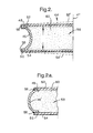
- Gas spring 44 comprises a closed frame element 46 having axis 47 and preferably is formed in a trough shape to resist radial deformation under load.
- Frame element 46,46' may be concave inwards as shown in FIG.2 or outwards as shown in FIG.2a to equal effect.
- Frame element 46,46' includes first and second axial surfaces 48,50 to which first and second membranes 52,54, respectively, are continuously attached as by laser welding 56 to form a flattened pillow enclosing a chamber 58.
- membranes 52,54 are formed of a flexible high-temperature metal alloy, for example, Haynes 160, 214, 230, 825, or 901; a Hastelloy; or Inconel DS, 625, or 718.
- membranes 52,54 are between about 0.005 inch and 0.010 inch in thickness.
- Chamber 58 is filled with a gas 60, preferably air, which may be installed in known fashion at any desired pressure above or below atmospheric for any specific application; one atmosphere is currently preferred for fuel cell uses.
- the operative principle of the invention is the use of a captive gas volume to maintain seal compression over a range of temperatures.
- a volume of gas in accordance with the invention may be captured in a wide variety of structures, all of which are comprehended by the invention.
- a separate gas spring structure 44 may be omitted and a chamber 58' created simply by flexibly sealing the space between spring holder 20 and spring retaining plate 26.
- a corrugated, flexible membrane 62 is attached continuously along a first edge 64 to spring holder 20 and along a second edge 66 to spring retaining plate 26 of the fuel cell stack.
- a simplified gas spring 44' in accordance with the invention may be formed for use in some applications by omitting frame element 46 from spring 44 and directly sealing membrane 52 to membrane 54 as by laser welds 56 to form a gas-filled pillow.
- a combined mechanical - gas spring 44" in accordance with the invention may be formed using mechanical spring 57 enclosed in two-part membrane spring of the type shown in FIG. 2b.
- mechanical spring 57 enclosed in two-part membrane spring of the type shown in FIG. 2b.
- Optional stop element 59 attached, for example, to the inside surface of membranes 52,54 serves to prevent excessive inward travel of membranes 52,54 under low temperature conditions and over-deflection of spring 57 beyond its yield limit.
- FIG. 2c discloses a particular type of spring, any spring means that applies a compressive load to the stacks, used in conjunction with a gas spring, is comprehended by this invention.
- FIG. 2c discloses a two-part membrane gas spring used in conjunction with a mechanical spring, it is understood that a mechanical spring can be used in conjunction with any of gas spring embodiments shown in FIGS. 2a, 2b and 4, and be in accordance with this invention.
- FIG. 2c discloses the gas and mechanical springs to be functionally in parallel with each other and one set of stops operating for both springs, it is understood that the gas and mechanical springs can be functionally in series with each other, such as by incorporating the mechanical spring outside of chamber 58, and for each spring to have its own set of stops.
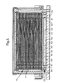
- FIG. 5 yet another embodiment of the current invention is shown wherein a gas spring such as, for example, one of the two part construction shown in FIG. 2b is positioned below the fuel cell stacks rather than above the fuel cell stacks, replacing gasket element 42. In this position, the gas spring provides compensation for both a loss of compression and lateral shear caused by the differing thermal growth of materials.
- a gas spring such as, for example, one of the two part construction shown in FIG. 2b is positioned below the fuel cell stacks rather than above the fuel cell stacks, replacing gasket element 42. In this position, the gas spring provides compensation for both a loss of compression and lateral shear caused by the differing thermal growth of materials.
- membrane 52 is first sealably joined to membrane 54, such as by laser welding 56.
- Chamber 58 formed therebetween is filled with gas 60, preferably air, to form a gas spring 144.
- Apertures 61, formed in edge regions of gas spring 144 align with similarly shaped apertures in supply and exhaust manifold 40, base plate 18, and stack 12, and provide passageways 39 for carrying oxygen and hydrogen to fuel modules 14.
- gas spring 144 serves both to add compressive force to the stack and to seal around oxygen or hydrogen passageways 39.
Applications Claiming Priority (4)
| Application Number | Priority Date | Filing Date | Title |
|---|---|---|---|
| US39102802P | 2002-06-24 | 2002-06-24 | |
| US391028P | 2002-06-24 | ||
| US388129 | 2003-03-13 | ||
| US10/388,129 US20030235723A1 (en) | 2002-06-24 | 2003-03-13 | Passive gas spring for solid-oxide fuel cell stack loading |
Publications (2)
| Publication Number | Publication Date |
|---|---|
| EP1416569A2 true EP1416569A2 (de) | 2004-05-06 |
| EP1416569A3 EP1416569A3 (de) | 2004-07-14 |
Family
ID=29739992
Family Applications (1)
| Application Number | Title | Priority Date | Filing Date |
|---|---|---|---|
| EP03076660A Withdrawn EP1416569A3 (de) | 2002-06-24 | 2003-05-28 | Passive Gasfeder zur komprimierung eines Festoxid-Brennstoffzellenstapel |
Country Status (2)
| Country | Link |
|---|---|
| US (1) | US20030235723A1 (de) |
| EP (1) | EP1416569A3 (de) |
Cited By (4)
| Publication number | Priority date | Publication date | Assignee | Title |
|---|---|---|---|---|
| WO2006075050A1 (en) * | 2005-01-13 | 2006-07-20 | Wärtsilä Finland Oy | Arrangement for compressing fuel cells in a fuel cell stack |
| CN101994833A (zh) * | 2009-08-25 | 2011-03-30 | 哈米尔顿森德斯特兰德公司 | 叠片组件密封方法及装置 |
| EP2330674A1 (de) * | 2008-10-02 | 2011-06-08 | NGK Sparkplug Co., Ltd. | Festoxidbrennstoffbatterie |
| DE102016115828A1 (de) * | 2016-08-25 | 2018-03-01 | Audi Ag | Zellanordnung, insbesondere für eine Brennstoffzelle oder Batterie |
Families Citing this family (8)
| Publication number | Priority date | Publication date | Assignee | Title |
|---|---|---|---|---|
| US6797425B2 (en) * | 2002-12-24 | 2004-09-28 | Fuelcell Energy, Inc. | Fuel cell stack compressive loading system |
| US20040265659A1 (en) * | 2003-06-26 | 2004-12-30 | Richardson Curtis A. | Pressure control system for fuel cell gas spring |
| US7879503B2 (en) * | 2005-08-19 | 2011-02-01 | GM Global Technology Operations LLC | Fuel cell stack including bypass |
| US9153834B2 (en) * | 2011-11-21 | 2015-10-06 | Delphi Technologies, Inc. | Fuel cell stack assembly with pressure balanced load mechanism |
| JP6025691B2 (ja) * | 2013-11-05 | 2016-11-16 | 本田技研工業株式会社 | 差圧式高圧水電解装置 |
| GB2530022A (en) * | 2014-09-02 | 2016-03-16 | Intelligent Energy Ltd | Fuel cell compression |
| JP7423381B2 (ja) | 2020-03-27 | 2024-01-29 | 大阪瓦斯株式会社 | 電気化学モジュール、電気化学装置及びエネルギーシステム |
| CN114566689B (zh) * | 2022-02-10 | 2024-01-19 | 浙江氢邦科技有限公司 | 一种平管式电池堆气腔封装用具及其电堆气腔封装方法 |
Citations (22)
| Publication number | Priority date | Publication date | Assignee | Title |
|---|---|---|---|---|
| US2969974A (en) * | 1958-11-19 | 1961-01-31 | Universal Air Lift Inc | Spring booster device |
| GB915053A (en) * | 1958-05-03 | 1963-01-09 | Ridley Ind Ltd | Cushioning device |
| DE1246013B (de) * | 1960-08-17 | 1967-08-03 | Maschf Augsburg Nuernberg Ag | Gasfeder mit kleinem Federweg, insbesondere fuer Schienenfahrzeuge |
| US3599955A (en) * | 1969-10-08 | 1971-08-17 | Gen Motors Corp | Nested composite spring assembly with multiple auxiliary spring units |
| US3727899A (en) * | 1971-04-07 | 1973-04-17 | Air Lift Co | Spring suspension unit particularly for vehicle suspension systems |
| FR2224206A1 (en) * | 1973-04-06 | 1974-10-31 | Alsthom Cgee | Internally pressurised bellows arrangement - acting as electrode separator in electrochemical systems |
| DE2525333A1 (de) * | 1975-06-06 | 1976-12-16 | Arpad Dipl Ing Dr Bardocz | Schwingungsisolator mit luftdaempfung |
| JPS5854246A (ja) * | 1981-09-24 | 1983-03-31 | Junichi Isoda | シヨツクアブソ−バ− |
| JPS59215676A (ja) * | 1983-05-24 | 1984-12-05 | Hokuriku Electric Power Co Inc:The | 燃料電池の電池積層体締付装置 |
| US4604331A (en) * | 1984-05-29 | 1986-08-05 | The United States Of America As Represented By The United States Department Of Energy | Fuel cell separator plate with bellows-type sealing flanges |
| EP0329161A1 (de) * | 1988-02-19 | 1989-08-23 | Ishikawajima-Harima Heavy Industries Co., Ltd. | Anordnung zum Zusammenspannen eines Stapels von Brennstoffzellenelementen |
| DE3913912A1 (de) * | 1989-04-27 | 1990-10-31 | Karl Dr Ing Bittel | Hydraulischer einrohr-gasdruck-stossdaempfer |
| EP0538587A1 (de) * | 1991-10-25 | 1993-04-28 | M-C Power Corporation | Ausgleichseinrichtung für die Klemmkraft an Brennstoffzellen |
| DE4336850A1 (de) * | 1993-10-28 | 1995-05-04 | Solentec Ges Fuer Solare Und E | Verfahren und Vorrichtung zum Verpressen eines Stapels von Hochtemperatur-Brennstoffzellen |
| JPH07335243A (ja) * | 1994-06-06 | 1995-12-22 | Toyota Motor Corp | 燃料電池 |
| US5532073A (en) * | 1993-11-29 | 1996-07-02 | Kabushiki Kaisha Toshiba | Fuel cell |
| JPH09139225A (ja) * | 1995-11-13 | 1997-05-27 | Toshiba Corp | 燃料電池の締め付け装置 |
| WO1997048921A1 (en) * | 1996-06-19 | 1997-12-24 | Howell William B | Pneumatic spring and method of manufacture |
| US5736269A (en) * | 1992-06-18 | 1998-04-07 | Honda Giken Kogyo Kabushiki Kaisha | Fuel cell stack and method of pressing together the same |
| DE19852363C1 (de) * | 1998-11-13 | 2000-05-18 | Mtu Friedrichshafen Gmbh | Brennstoffzellenanordnung |
| US6332602B1 (en) * | 2001-03-30 | 2001-12-25 | Yuzuru Oishi | Vehicle suspension having annular air chamber |
| US20020010977A1 (en) * | 2000-06-08 | 2002-01-31 | Luciano Salice | Apparatus for the damping of impacts, preferably the impacts of furniture doors or drawers |
Family Cites Families (4)
| Publication number | Priority date | Publication date | Assignee | Title |
|---|---|---|---|---|
| US5441825A (en) * | 1994-01-24 | 1995-08-15 | Westinghouse Electric Corporation | Battery electrode compression mechanism |
| US5789091C1 (en) * | 1996-11-19 | 2001-02-27 | Ballard Power Systems | Electrochemical fuel cell stack with compression bands |
| US6200698B1 (en) * | 1999-08-11 | 2001-03-13 | Plug Power Inc. | End plate assembly having a two-phase fluid-filled bladder and method for compressing a fuel cell stack |
| US7037618B2 (en) * | 2002-06-05 | 2006-05-02 | Lynntech, Inc. | Apparatus and method for compressing a stack of electrochemical cells |
-
2003
- 2003-03-13 US US10/388,129 patent/US20030235723A1/en not_active Abandoned
- 2003-05-28 EP EP03076660A patent/EP1416569A3/de not_active Withdrawn
Patent Citations (22)
| Publication number | Priority date | Publication date | Assignee | Title |
|---|---|---|---|---|
| GB915053A (en) * | 1958-05-03 | 1963-01-09 | Ridley Ind Ltd | Cushioning device |
| US2969974A (en) * | 1958-11-19 | 1961-01-31 | Universal Air Lift Inc | Spring booster device |
| DE1246013B (de) * | 1960-08-17 | 1967-08-03 | Maschf Augsburg Nuernberg Ag | Gasfeder mit kleinem Federweg, insbesondere fuer Schienenfahrzeuge |
| US3599955A (en) * | 1969-10-08 | 1971-08-17 | Gen Motors Corp | Nested composite spring assembly with multiple auxiliary spring units |
| US3727899A (en) * | 1971-04-07 | 1973-04-17 | Air Lift Co | Spring suspension unit particularly for vehicle suspension systems |
| FR2224206A1 (en) * | 1973-04-06 | 1974-10-31 | Alsthom Cgee | Internally pressurised bellows arrangement - acting as electrode separator in electrochemical systems |
| DE2525333A1 (de) * | 1975-06-06 | 1976-12-16 | Arpad Dipl Ing Dr Bardocz | Schwingungsisolator mit luftdaempfung |
| JPS5854246A (ja) * | 1981-09-24 | 1983-03-31 | Junichi Isoda | シヨツクアブソ−バ− |
| JPS59215676A (ja) * | 1983-05-24 | 1984-12-05 | Hokuriku Electric Power Co Inc:The | 燃料電池の電池積層体締付装置 |
| US4604331A (en) * | 1984-05-29 | 1986-08-05 | The United States Of America As Represented By The United States Department Of Energy | Fuel cell separator plate with bellows-type sealing flanges |
| EP0329161A1 (de) * | 1988-02-19 | 1989-08-23 | Ishikawajima-Harima Heavy Industries Co., Ltd. | Anordnung zum Zusammenspannen eines Stapels von Brennstoffzellenelementen |
| DE3913912A1 (de) * | 1989-04-27 | 1990-10-31 | Karl Dr Ing Bittel | Hydraulischer einrohr-gasdruck-stossdaempfer |
| EP0538587A1 (de) * | 1991-10-25 | 1993-04-28 | M-C Power Corporation | Ausgleichseinrichtung für die Klemmkraft an Brennstoffzellen |
| US5736269A (en) * | 1992-06-18 | 1998-04-07 | Honda Giken Kogyo Kabushiki Kaisha | Fuel cell stack and method of pressing together the same |
| DE4336850A1 (de) * | 1993-10-28 | 1995-05-04 | Solentec Ges Fuer Solare Und E | Verfahren und Vorrichtung zum Verpressen eines Stapels von Hochtemperatur-Brennstoffzellen |
| US5532073A (en) * | 1993-11-29 | 1996-07-02 | Kabushiki Kaisha Toshiba | Fuel cell |
| JPH07335243A (ja) * | 1994-06-06 | 1995-12-22 | Toyota Motor Corp | 燃料電池 |
| JPH09139225A (ja) * | 1995-11-13 | 1997-05-27 | Toshiba Corp | 燃料電池の締め付け装置 |
| WO1997048921A1 (en) * | 1996-06-19 | 1997-12-24 | Howell William B | Pneumatic spring and method of manufacture |
| DE19852363C1 (de) * | 1998-11-13 | 2000-05-18 | Mtu Friedrichshafen Gmbh | Brennstoffzellenanordnung |
| US20020010977A1 (en) * | 2000-06-08 | 2002-01-31 | Luciano Salice | Apparatus for the damping of impacts, preferably the impacts of furniture doors or drawers |
| US6332602B1 (en) * | 2001-03-30 | 2001-12-25 | Yuzuru Oishi | Vehicle suspension having annular air chamber |
Non-Patent Citations (4)
| Title |
|---|
| PATENT ABSTRACTS OF JAPAN vol. 007, no. 141 (M-223), 21 June 1983 (1983-06-21) & JP 58 054246 A (JIYUNICHI ISODA), 31 March 1983 (1983-03-31) * |
| PATENT ABSTRACTS OF JAPAN vol. 009, no. 085 (E-308), 13 April 1985 (1985-04-13) & JP 59 215676 A (HOKURIKU DENRIYOKU KK), 5 December 1984 (1984-12-05) * |
| PATENT ABSTRACTS OF JAPAN vol. 1996, no. 04, 30 April 1996 (1996-04-30) & JP 07 335243 A (TOYOTA MOTOR CORP), 22 December 1995 (1995-12-22) * |
| PATENT ABSTRACTS OF JAPAN vol. 1997, no. 09, 30 September 1997 (1997-09-30) & JP 09 139225 A (TOSHIBA CORP), 27 May 1997 (1997-05-27) * |
Cited By (6)
| Publication number | Priority date | Publication date | Assignee | Title |
|---|---|---|---|---|
| WO2006075050A1 (en) * | 2005-01-13 | 2006-07-20 | Wärtsilä Finland Oy | Arrangement for compressing fuel cells in a fuel cell stack |
| EP2330674A1 (de) * | 2008-10-02 | 2011-06-08 | NGK Sparkplug Co., Ltd. | Festoxidbrennstoffbatterie |
| EP2330674A4 (de) * | 2008-10-02 | 2013-11-27 | Ngk Spark Plug Co | Festoxidbrennstoffbatterie |
| US9123936B2 (en) | 2008-10-02 | 2015-09-01 | Ngk Spark Plug Co., Ltd. | Solid oxide fuel cell apparatus |
| CN101994833A (zh) * | 2009-08-25 | 2011-03-30 | 哈米尔顿森德斯特兰德公司 | 叠片组件密封方法及装置 |
| DE102016115828A1 (de) * | 2016-08-25 | 2018-03-01 | Audi Ag | Zellanordnung, insbesondere für eine Brennstoffzelle oder Batterie |
Also Published As
| Publication number | Publication date |
|---|---|
| EP1416569A3 (de) | 2004-07-14 |
| US20030235723A1 (en) | 2003-12-25 |
Similar Documents
| Publication | Publication Date | Title |
|---|---|---|
| US7270906B2 (en) | Solid-oxide fuel cell module for a fuel cell stack | |
| CN100423347C (zh) | 带有作为冷却剂层的导电泡沫的燃料电池双极板 | |
| US4345009A (en) | Fuel cell stack compressive loading system | |
| US20070248855A1 (en) | Fuel-Cell Stack Comprising a Tensioning Device | |
| US4839247A (en) | Static regenerative fuel cell system for use in space | |
| EP3016192A1 (de) | Brennstoffzelle und verfahren zur herstellung davon | |
| US20090220833A1 (en) | Fuel Cell Device | |
| EP1416569A2 (de) | Passive Gasfeder zur Komprimierung eines Festoxid-Brennstoffzellenstapels | |
| CA2613652A1 (en) | An electrochemical cell stack | |
| CA2690185A1 (en) | Fuel cell | |
| US5298342A (en) | Fuel cell crossover arrestor and pressure seal | |
| US20010008722A1 (en) | Integral screen/frame assembly for an electrochemical cell | |
| US11394039B2 (en) | Electro-chemical reaction unit having glass seal member composed of vertically long crystal grains, and electro-chemical reaction cell stack, and electro-chemical reaction unit production method comprising same | |
| US7001685B2 (en) | Fuel cell stack assembly load frame with compression spring | |
| US10476087B2 (en) | Fuel-cell power generation unit and fuel-cell stack | |
| US20040265659A1 (en) | Pressure control system for fuel cell gas spring | |
| JP2008078148A (ja) | 燃料電池 | |
| US20100040923A1 (en) | Heat insulation cell for fuel cell and manufacturing method of the same | |
| US20050255363A1 (en) | Contact element for a fuel cell stack | |
| US7402357B2 (en) | Gas-filled gasket for a solid-oxide fuel cell assembly | |
| JP4447133B2 (ja) | 燃料電池 | |
| US10665872B2 (en) | Fuel cell stack and method for manufacturing fuel cell stack | |
| KR20010060112A (ko) | 고분자 전해질 연료전지 | |
| US20100043892A1 (en) | Valve for fuel cell based power generator | |
| US20230282865A1 (en) | Fuel Cell Heat Treatment Method and Apparatus |
Legal Events
| Date | Code | Title | Description |
|---|---|---|---|
| PUAI | Public reference made under article 153(3) epc to a published international application that has entered the european phase |
Free format text: ORIGINAL CODE: 0009012 |
|
| AK | Designated contracting states |
Kind code of ref document: A2 Designated state(s): AT BE BG CH CY CZ DE DK EE ES FI FR GB GR HU IE IT LI LU MC NL PT RO SE SI SK TR |
|
| AX | Request for extension of the european patent |
Extension state: AL LT LV MK |
|
| PUAL | Search report despatched |
Free format text: ORIGINAL CODE: 0009013 |
|
| AK | Designated contracting states |
Kind code of ref document: A3 Designated state(s): AT BE BG CH CY CZ DE DK EE ES FI FR GB GR HU IE IT LI LU MC NL PT RO SE SI SK TR |
|
| AX | Request for extension of the european patent |
Extension state: AL LT LV MK |
|
| 17P | Request for examination filed |
Effective date: 20050114 |
|
| AKX | Designation fees paid |
Designated state(s): DE FR GB |
|
| STAA | Information on the status of an ep patent application or granted ep patent |
Free format text: STATUS: THE APPLICATION IS DEEMED TO BE WITHDRAWN |
|
| 18D | Application deemed to be withdrawn |
Effective date: 20060621 |