EP1415875A2 - Betätigungseinrichtung für eine Bremse - Google Patents
Betätigungseinrichtung für eine Bremse Download PDFInfo
- Publication number
- EP1415875A2 EP1415875A2 EP03022689A EP03022689A EP1415875A2 EP 1415875 A2 EP1415875 A2 EP 1415875A2 EP 03022689 A EP03022689 A EP 03022689A EP 03022689 A EP03022689 A EP 03022689A EP 1415875 A2 EP1415875 A2 EP 1415875A2
- Authority
- EP
- European Patent Office
- Prior art keywords
- actuating device
- hand lever
- driver
- actuating
- lever
- Prior art date
- Legal status (The legal status is an assumption and is not a legal conclusion. Google has not performed a legal analysis and makes no representation as to the accuracy of the status listed.)
- Granted
Links
Images


Classifications
-
- B—PERFORMING OPERATIONS; TRANSPORTING
- B60—VEHICLES IN GENERAL
- B60T—VEHICLE BRAKE CONTROL SYSTEMS OR PARTS THEREOF; BRAKE CONTROL SYSTEMS OR PARTS THEREOF, IN GENERAL; ARRANGEMENT OF BRAKING ELEMENTS ON VEHICLES IN GENERAL; PORTABLE DEVICES FOR PREVENTING UNWANTED MOVEMENT OF VEHICLES; VEHICLE MODIFICATIONS TO FACILITATE COOLING OF BRAKES
- B60T7/00—Brake-action initiating means
- B60T7/02—Brake-action initiating means for personal initiation
- B60T7/08—Brake-action initiating means for personal initiation hand actuated
- B60T7/10—Disposition of hand control
- B60T7/102—Disposition of hand control by means of a tilting lever
Definitions
- the invention relates to an actuating device for a manually operated brake, in particular parking brake, of an industrial truck, with a pivotable stored operating lever, which is connected to the brake by means of a transmission means Active connection is established.
- Actuators of this type for the parking brake of an industrial truck in particular a counterbalance forklift, can be next to one Driver's workplace, for example a driver's seat, on an engine or Battery hood to be arranged.
- the actuator on the front area of the overhead guard, the so-called front structure, one Counterbalance forklift can be arranged.
- the actuator When the actuator is arranged on the front of the truck the operating lever protrudes into the area in the release position or the braking position of the driver's workplace. This can lead to a disability for the Operator come especially during ascending and descending. Is on the Actuating device no locking device for the braking position or Provided release position, it can occur with a random touch of the Actuation lever during ascending or descending to an unwanted actuation of the actuating lever and thus for actuating or releasing the parking brake come. Particularly in the case of actuators in which the actuating lever protruding into the driver's workplace in the braking position can be caused by a random Touching the operating lever while the ascent or descent Operator the parking brake to be released unintentionally.
- the present invention has for its object an actuator to provide the genus mentioned at the outset, which hinders the Operator avoids and a high security against unintentional operation having.
- the actuating lever a hand lever and a driver element which can be actuated by means of the hand lever has, the driver element in connection with the transmission means stands and in the braking position or in the release position Mit supportiveelemerit the hand lever is movable.
- the hand lever can thus be independent of that Driver element are moved. This ensures in a simple manner that the Hand lever when in the release position or the braking position Driver element can be pivoted into the respective other position.
- On The control lever protrudes into the driver's workplace and an unintentional one Operating the hand lever can thus be avoided effectively.
- driver element of the hand lever can be actuated in the release position.
- the hand lever protrudes into the driver's workplace, it can thus be achieved that when the driver element is in the braking position, move the hand lever into the Release position can be pivoted back.
- Actuator is thereby a handicap to the operator during Avoid getting on and off, which will continue to cause accidental activation of the hand lever and thus an unwanted release of the brake effectively prevented can be.
- the driver element is designed as a driver lever, the Hand lever and the driver lever can be pivoted about a common axis of rotation are stored.
- the driver device can be easily on the driver lever arranged crossbar are formed.
- the driver element can Invention is designed as a toggle lever.
- the brake as Wheel lock; can therefore an unintentional actuation of the hand lever and a Disability of the operator during ascending or descending can be avoided.
- the driver element is designed as a ratchet.
- the brake is designed as a ratchet brake.
- the brake can also an unintended with the actuating device according to the invention Avoid applying the brake.
- a stop is expediently provided for the release position, which stops with the Hand lever can be brought into operative connection.
- the hand lever on the stop for the release position can be fixed by means of a locking device, can fall back of the hand lever in the braking position and noise caused by rattling of the Avoid using the hand lever while the truck is operating.
- the locking device is particularly advantageous as a spring or snap element educated.
- a stop for the braking position is expedient with the driver element can be brought into operative connection.
- the driver element can be moved easily by means of the hand lever Brake position in the release position, if according to a advantageous development of the invention, a coupling element is provided by means of which the driver element with the hand lever to act on Driver element is connectable from the braking position into the release position.
- the coupling element can be used as a locking pin be formed.
- the coupling element is expediently by means of an actuating means actuated.
- an actuating means With an actuating means, the coupling element can easily Actuated and thus the hand lever with the driver element to release the Brake are coupled.
- the actuating means can be arranged on the actuating lever Actuation button be formed. It is also possible to switch the actuating means on to form the lever arranged lever.
- An increased operational reliability of the brake can be achieved if the driver element can be fixed in the braking position by means of a locking element. This can Driver element can be securely fixed in the braking position.
- the locking element is expediently designed as a latching element.
- the locking element is detachable by means of the actuating means.
- the actuating device is on the front structure of an industrial truck designed as a counterbalanced forklift.
- In the braking position can be achieved by swiveling the hand lever back into the Release position a handicap of the operator when getting on and off as well as a unintentional actuation of the actuating device avoided in the release position be, whereby a high security of the actuator against unintentional actuation is achieved.
- FIG. 1 shows an industrial truck 1 designed as a counterbalance forklift shown.
- a driver's workplace is located within a driver's canopy 2 formed, which is formed for example by a driver's seat 3.
- the driver's seat 3 can be arranged on a battery or engine hood 4.
- a control console 6 for example a dashboard, arranged.
- On the control panel 6 is a steering wheel 7 and one as an operating lever 10 trained actuator for a parking brake, for example trained brake arranged.
- the operating lever 10 In the vertical position, the operating lever 10 is in a release position, in which the brake is released. Almost horizontal in the dashed line Position is the operating lever 10 in the braking position in which the brake is applied in the braking position.
- FIG. 2 shows an actuating lever 10 according to the invention Actuator shown.
- the operating lever 10 has a hand lever 11 and a driver element 12.
- the driver element 12 and the hand lever 11 are rotatably mounted about a common axis of rotation 13.
- the driver element 12 is designed as a driver lever 14, in particular a toggle lever, on which the Axis of rotation 13 spaced a transmission means 15, for example one with the brake shown related brake cable or brake linkage, is attached by means of a pivot point 18.
- the hand lever 11 is designed, for example, as a tube and on the axis of rotation 13 removed area with a handle 16.
- a stop 17 for the release position for example on the control console 6 can be arranged or formed, is in the vertical position shown of the operating lever 10 with the hand lever 11 in operative connection.
- the driver device 19 arranged perpendicular to the plane of the drawing.
- the driver device 19 can, for example, as on the driver lever 14 trained crossbar, in particular cross pin or crossbar, be designed.
- the driver device 19 is opposite to the axis of rotation 13 Point of attack of the transmission means 15 arranged on the driver element 12.
- the Driver device 19 In the release position of the actuating lever 10 shown is the Driver device 19 in contact with the hand lever 11 due to the Transmission means 15 exerted on the driver element 12 tensile force.
- the coupling element 20 is as longitudinally displaceable locking pin 21 formed on the hand lever 11 or is arranged within the hand lever 11 and with the driver device 19 of the Driver element 12 can be brought into operative connection.
- the locking pin 21 is by means of an actuating means 22, for example one on the end face of the Hand lever 11 arranged operating button 23, actuated. By means of a spring 24, the locking pin 21 is acted upon in FIG. 1 above.
- a stop 25 for the braking position can still be on the control console 6 be arranged, which can be brought into connection with the driver element 12.
- the braking position is applied to the hand lever 11 in the direction 30 according to FIG. 3.
- the driver element 12 is at a Pivoting the operating lever 11 also pivoted in the direction 30.
- the Stop 25 for the braking position limits the movement of the driver element 12 and thus the hand lever 11 in the braking position.
- the pivot point 18 is in the illustrated braking position of the Actuating lever 10 to the right of the axis of rotation 13, so that a dead center lock is achieved.
- the Mitnehrrierelement 12 is by the transmission means 15th exerted tensile force in contact with the stop 25 and thus in the braking position held, whereby the brake in the braking position via the transmission means 15 is actuated.
- the hand lever 11 In the braking position of the driver element 12, the hand lever 11 can be in the Release position according to Figure 4 are pivoted back. No more illustrated locking device, for example a spring or one The hand lever 11 can engage the stop element 17 in this case be held to a fall back of the hand lever 11 or a rattle in the Avoid operating the industrial truck. In the braking position the brake can thus the hand lever 11 can be pivoted back into the release position, whereby at Actuating device 10 arranged on the front structure of the industrial truck 1 the hand lever 11 is not a hindrance to the operator during the opening and Descending forms. In addition, by returning the hand lever 11 into the Release position with the brake applied to the hand lever 11 protected against unintentional actuation, causing accidental release of the brake an unintentional actuation of the hand lever 11 can be effectively avoided can.
- No more illustrated locking device for example a spring or one
- the hand lever 11 can engage the stop element 17 in this case be held to a fall back of the hand lever 11 or a rattle in the Avoid
- the hand lever 11 is started from that in FIG. 4 position shown pivoted into the position shown in Figure 3.
- the locking pin 21 can in this case with the surface opposite the hand lever 11 as a cross bar trained driver device 19 come into operative connection.
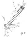
- Actuator 22 can thus the driver element 12 together with the Hand lever 11 - as shown in FIG. 5 - in direction 31 in the direction shown in FIG. 1 shown release position are applied, in which the brake is released.
Landscapes
- Engineering & Computer Science (AREA)
- Transportation (AREA)
- Mechanical Engineering (AREA)
- Braking Elements And Transmission Devices (AREA)
- Braking Arrangements (AREA)
- Regulating Braking Force (AREA)
Abstract
Description
- Figur 1
- ein Flurtörderzeug mit einer Betätigungseinrichtung des Standes der Technik,
- Figur 2
- eine erfindungsgemäße Betätigungseinrichtung in der Lösestellung,
- Figur 3
- die Betätigungseinrichtung gemäß der Figur 2 in der Bremsstellung,
- Figur 4
- die Betätigungseinrichtung gemäß der Figur 2 in der Bremsstellung bei zurückgeschwenktem Handhebel und
- Figur 5
- die ertindungsgemäße Betätigungseinrichtung bei einer Beaufschlagung der Bremse von der Bremsstellung in die Lösestellung.
Claims (21)
- Betätigungseinrichtung für eine manuell betätigbare Bremse, insbesondere Feststellbremse, eines Flurförderzeugs, mit einem schwenkbar gelagerten Betätigungshebel, der mittels eines Übertragungsmittels mit der Bremse in Wirkverbindung steht, dadurch gekennzeichnet, dass der Betätigungshebel (10) einen Handhebel (11) und ein mittels des Handhebels (11) betätigbares Mitnehmerelement (12) aufweist, wobei das Mitnehmerelement (12) mit dem Übertragungsmittel (15) in Verbindung steht und bei in der Bremsstellung oder der Lösestellung befindlichem Mitnehmerelement (12) der Handhebel (11) bewegbar ist.
- Betätigungseinrichtung nach Anspruch 1, dadurch gekennzeichnet, dass bei in der Bremsstellung befindlichem Mitnehmerelement (12) der Handhebel (11) in die Lösestellung betätigbar ist.
- Betätigungseinrichtung nach Anspruch 1 oder 2, dadurch gekennzeichnet, dass das Mitnehmerelement (12) als Mitnehmerhebel (14) ausgebildet ist, wobei der Handhebel (11) und der Mitnehmerhebel (14) um eine gemeinsame Drehachse (13) schwenkbar gelagert sind.
- Betätigungseinrichtung nach einem der Ansprüche 1 bis 3, dadurch gekennzeichnet, dass das Mitnehmerelement (12) mit einer mit dem Handhebel (11) in Wirkverbindung bringbaren Mitnehmereinrichtung (19) versehen ist.
- Betätigungseinrichtung nach Anspruch 4, dadurch gekennzeichnet, dass die Mitnehmereinrichtung (19) als Querriegel ausgebildet ist.
- Betätigungseinrichtung nach einem der Ansprüche 1 bis 5, dadurch gekennzeichnet, dass das Mitnehmerelement (12) als Kniehebel ausgebildet ist.
- Betätigungseinrichtung nach einem der Ansprüche 1 bis 5, dadurch gekennzeichnet, dass das Mitnehmerelement (12) als Ratsche ausgebildet ist.
- Betätigungseinrichtung nach einem der Ansprüche 1 bis 7, dadurch gekennzeichnet, dass in der Bremsstellung eine Totpunktverriegelung vorgesehen ist.
- Betätigungseinrichtung nach einem der Ansprüche 1 bis 8, dadurch gekennzeichnet, dass ein Anschlag (17) für die Lösestellung vorgesehen ist, der mit dem Handhebel (11) in Wirkverbindung bringbar ist.
- Betätigungseinrichtung nach Anspruch 9, dadurch gekennzeichnet, dass der Handhebel (11) an dem Anschlag für die Lösestellung mittels einer Feststelleinrichtung festsetzbar ist.
- Betätigungseinrichtung nach Anspruch 10, dadurch gekennzeichnet, dass die Feststelleinrichtung als Feder oder Einrastelement ausgebildet ist.
- Betätigungseinrichtung nach einem der Ansprüche 1 bis 11, dadurch gekennzeichnet, dass ein Anschlag (25) für die Bremsstellung vorgesehen ist, der mit dem Mitnehmerelement (12) in Wirkverbindung bringbar ist.
- Betätigungseinrichtung nach einem der Ansprüche 1 bis 12, dadurch gekennzeichnet, dass ein Kopplungselement (20) vorgesehen ist mittels dem das Mitnehmerelement (12) mit dem Handhebel (11) zum Beaufschlagen des Mitnehmerelements (12) von der Bremsstellung in die Lösestellung verbindbar ist.
- Betätigungseinrichtung nach Anspruch 13, dadurch gekennzeichnet, dass das Kopplungselement (20) als Verriegelungsstift (21) ausgebildet ist.
- Betätigungseinrichtung nach Anspruch 13 oder 14, dadurch gekennzeichnet, dass das Kopplungselement (20) am Handhebel (11) angeordnet ist und mit der Mitnehmereinrichtung (19) des Mitnehmerelements (12) in Wirkverbindung bringbar ist.
- Betätigungseinrichtung nach einem der Ansprüche 13 bis 15, dadurch gekennzeichnet, dass das Kopplungselement (20) mittels eines Betätigungsmittels (22) betätigbar ist.
- Betätigungseinrichtung nach Anspruch 16, dadurch gekennzeichnet, dass das Betätigungsmittel (22) als an dem Handhebel (11) angeordneter Betätigungsknopf (23) ausgebildet ist.
- Betätigungseinrichtung nach einem der Ansprüche 1 bis 17, dadurch gekennzeichnet, dass das Mitnehmerelement (12) in der Bremsstellung mittels eines Feststellelement festsetzbar ist.
- Betätigungseinrichtung nach Anspruch 18, dadurch gekennzeichnet, dass das Feststellelement als Einrastelement ausgebildet ist.
- Betätigungseinrichtung nach Anspruch 18 oder 19, dadurch gekennzeichnet, dass das Feststellelement mittels des Betätigungsmittels (22) lösbar ist.
- Betätigungseinrichtung nach einem der vorangegangenen Ansprüche, dadurch gekennzeichnet, dass die Betätigungseinrichtung (10) am Vorderaufbau (6) eines als Gegengewichtsgabelstapler ausgebildeten Flurförderzeugs (1) angeordnet ist.
Applications Claiming Priority (2)
| Application Number | Priority Date | Filing Date | Title |
|---|---|---|---|
| DE2002150139 DE10250139A1 (de) | 2002-10-28 | 2002-10-28 | Betätigungseinrichtung für eine Bremse |
| DE10250139 | 2002-10-28 |
Publications (3)
| Publication Number | Publication Date |
|---|---|
| EP1415875A2 true EP1415875A2 (de) | 2004-05-06 |
| EP1415875A3 EP1415875A3 (de) | 2005-02-09 |
| EP1415875B1 EP1415875B1 (de) | 2006-05-24 |
Family
ID=32087256
Family Applications (1)
| Application Number | Title | Priority Date | Filing Date |
|---|---|---|---|
| EP20030022689 Expired - Lifetime EP1415875B1 (de) | 2002-10-28 | 2003-10-07 | Betätigungseinrichtung für eine Bremse |
Country Status (2)
| Country | Link |
|---|---|
| EP (1) | EP1415875B1 (de) |
| DE (2) | DE10250139A1 (de) |
Cited By (1)
| Publication number | Priority date | Publication date | Assignee | Title |
|---|---|---|---|---|
| EP2308729A1 (de) * | 2009-10-09 | 2011-04-13 | STILL GmbH | Fahrzeug, insbesondere Elektrofahrzeug, mit einer elektrisch betätigten Feststellbremse |
Families Citing this family (1)
| Publication number | Priority date | Publication date | Assignee | Title |
|---|---|---|---|---|
| DE102009013116A1 (de) | 2009-03-13 | 2010-09-16 | Still Gmbh | Bremsbetätigungseinrichtung zur Betätigung einer Bremse einer fahrbaren Arbeitsmaschine |
Family Cites Families (3)
| Publication number | Priority date | Publication date | Assignee | Title |
|---|---|---|---|---|
| JP2525009Y2 (ja) * | 1991-08-09 | 1997-02-05 | 株式会社大井製作所 | パーキングブレーキの操作装置 |
| KR100199634B1 (ko) * | 1996-12-30 | 1999-06-15 | 이충곤 | 작동레버를 접을 수 있는 핸드 브레이크 |
| DE10027019B4 (de) * | 2000-05-31 | 2006-06-14 | Daimlerchrysler Ag | Vorrichtung zum handbetätigten Spannen und Lösen einer Fahrzeugbremse mit wegschwenkbarem Betätigungshebel |
-
2002
- 2002-10-28 DE DE2002150139 patent/DE10250139A1/de not_active Withdrawn
-
2003
- 2003-10-07 EP EP20030022689 patent/EP1415875B1/de not_active Expired - Lifetime
- 2003-10-07 DE DE50303453T patent/DE50303453D1/de not_active Expired - Lifetime
Cited By (1)
| Publication number | Priority date | Publication date | Assignee | Title |
|---|---|---|---|---|
| EP2308729A1 (de) * | 2009-10-09 | 2011-04-13 | STILL GmbH | Fahrzeug, insbesondere Elektrofahrzeug, mit einer elektrisch betätigten Feststellbremse |
Also Published As
| Publication number | Publication date |
|---|---|
| DE10250139A1 (de) | 2004-05-06 |
| EP1415875B1 (de) | 2006-05-24 |
| DE50303453D1 (de) | 2006-06-29 |
| EP1415875A3 (de) | 2005-02-09 |
Similar Documents
| Publication | Publication Date | Title |
|---|---|---|
| EP0981078B1 (de) | Handbedienungselement | |
| EP0950634A2 (de) | Multifunktionshebel | |
| EP2138445B1 (de) | Bedienkonsole für ein Flurförderzeug | |
| DE19955767A1 (de) | Wählhebelsperrvorrichtung für Fahrzeuge | |
| DE19625497C1 (de) | Bedienelementanordnung zur Steuerung der Längs- und der Querbewegung eines Kraftfahrzeuges | |
| DE102005046318B4 (de) | Handbediengerät; Verfahren zur Bedienung des Brems- und des Gaspedals | |
| EP1415875A2 (de) | Betätigungseinrichtung für eine Bremse | |
| EP1422121B1 (de) | Deichsel für Handgabelhubwagen | |
| EP3626525B1 (de) | Fahrzeugsitz mit bedienungseinrichtung | |
| DE10254031B4 (de) | Deichsel für Handgabelhubwagen | |
| EP2724816A2 (de) | Angetriebene Werkzeugmaschine, insbesondere Winkelschleifer oder Geradschleifer | |
| EP1690820B1 (de) | Flurförderzeug mit einem Lenkgeber | |
| EP0941754B1 (de) | Spielzeugfahrzeug | |
| DE1246429B (de) | Steuerhandgriff fuer Flurfoerderfahrzeuge | |
| DE60308119T2 (de) | Deichselgesteuertes Flurförderfahrzeug und Steuerverfahren für ein derartiges Fahrzeug | |
| DE102009013116A1 (de) | Bremsbetätigungseinrichtung zur Betätigung einer Bremse einer fahrbaren Arbeitsmaschine | |
| EP2851247B9 (de) | Betätigungseinrichtung für eine Bremse | |
| EP2353949A2 (de) | Betätigungsvorrichtung für eine Feststellbremse | |
| DE102020110674A1 (de) | Fahrzeugtüraufbau | |
| DE102008045731B4 (de) | Deichselkopf für ein Flurförderzeug | |
| EP4023312B1 (de) | Spielfahrzeug | |
| EP2075214B1 (de) | Deichselkopf für ein Flurförderzeug | |
| DE19945459A1 (de) | Betätigungseinrichtung für eine Bremse | |
| DE102008010397A1 (de) | Gangwahlhebel | |
| DE2720213A1 (de) | Betaetigungselement fuer eine fahrzeugbremse |
Legal Events
| Date | Code | Title | Description |
|---|---|---|---|
| PUAI | Public reference made under article 153(3) epc to a published international application that has entered the european phase |
Free format text: ORIGINAL CODE: 0009012 |
|
| AK | Designated contracting states |
Kind code of ref document: A2 Designated state(s): AT BE BG CH CY CZ DE DK EE ES FI FR GB GR HU IE IT LI LU MC NL PT RO SE SI SK TR |
|
| AX | Request for extension of the european patent |
Extension state: AL LT LV MK |
|
| PUAL | Search report despatched |
Free format text: ORIGINAL CODE: 0009013 |
|
| AK | Designated contracting states |
Kind code of ref document: A3 Designated state(s): AT BE BG CH CY CZ DE DK EE ES FI FR GB GR HU IE IT LI LU MC NL PT RO SE SI SK TR |
|
| AX | Request for extension of the european patent |
Extension state: AL LT LV MK |
|
| 17P | Request for examination filed |
Effective date: 20050705 |
|
| AKX | Designation fees paid |
Designated state(s): DE FR GB IT |
|
| GRAP | Despatch of communication of intention to grant a patent |
Free format text: ORIGINAL CODE: EPIDOSNIGR1 |
|
| GRAS | Grant fee paid |
Free format text: ORIGINAL CODE: EPIDOSNIGR3 |
|
| GRAA | (expected) grant |
Free format text: ORIGINAL CODE: 0009210 |
|
| AK | Designated contracting states |
Kind code of ref document: B1 Designated state(s): DE FR GB IT |
|
| PG25 | Lapsed in a contracting state [announced via postgrant information from national office to epo] |
Ref country code: IT Free format text: LAPSE BECAUSE OF FAILURE TO SUBMIT A TRANSLATION OF THE DESCRIPTION OR TO PAY THE FEE WITHIN THE PRESCRIBED TIME-LIMIT;WARNING: LAPSES OF ITALIAN PATENTS WITH EFFECTIVE DATE BEFORE 2007 MAY HAVE OCCURRED AT ANY TIME BEFORE 2007. THE CORRECT EFFECTIVE DATE MAY BE DIFFERENT FROM THE ONE RECORDED. Effective date: 20060524 |
|
| REG | Reference to a national code |
Ref country code: GB Ref legal event code: FG4D Free format text: NOT ENGLISH |
|
| REF | Corresponds to: |
Ref document number: 50303453 Country of ref document: DE Date of ref document: 20060629 Kind code of ref document: P |
|
| GBT | Gb: translation of ep patent filed (gb section 77(6)(a)/1977) |
Effective date: 20060920 |
|
| ET | Fr: translation filed | ||
| PLBE | No opposition filed within time limit |
Free format text: ORIGINAL CODE: 0009261 |
|
| STAA | Information on the status of an ep patent application or granted ep patent |
Free format text: STATUS: NO OPPOSITION FILED WITHIN TIME LIMIT |
|
| 26N | No opposition filed |
Effective date: 20070227 |
|
| PGFP | Annual fee paid to national office [announced via postgrant information from national office to epo] |
Ref country code: GB Payment date: 20091023 Year of fee payment: 7 Ref country code: IT Payment date: 20091024 Year of fee payment: 7 |
|
| PGFP | Annual fee paid to national office [announced via postgrant information from national office to epo] |
Ref country code: FR Payment date: 20101109 Year of fee payment: 8 |
|
| PGFP | Annual fee paid to national office [announced via postgrant information from national office to epo] |
Ref country code: DE Payment date: 20101223 Year of fee payment: 8 |
|
| GBPC | Gb: european patent ceased through non-payment of renewal fee |
Effective date: 20101007 |
|
| PG25 | Lapsed in a contracting state [announced via postgrant information from national office to epo] |
Ref country code: GB Free format text: LAPSE BECAUSE OF NON-PAYMENT OF DUE FEES Effective date: 20101007 |
|
| PG25 | Lapsed in a contracting state [announced via postgrant information from national office to epo] |
Ref country code: IT Free format text: LAPSE BECAUSE OF NON-PAYMENT OF DUE FEES Effective date: 20101007 |
|
| REG | Reference to a national code |
Ref country code: FR Ref legal event code: ST Effective date: 20120629 |
|
| PG25 | Lapsed in a contracting state [announced via postgrant information from national office to epo] |
Ref country code: DE Free format text: LAPSE BECAUSE OF NON-PAYMENT OF DUE FEES Effective date: 20120501 |
|
| REG | Reference to a national code |
Ref country code: DE Ref legal event code: R119 Ref document number: 50303453 Country of ref document: DE Effective date: 20120501 |
|
| PG25 | Lapsed in a contracting state [announced via postgrant information from national office to epo] |
Ref country code: FR Free format text: LAPSE BECAUSE OF NON-PAYMENT OF DUE FEES Effective date: 20111102 |
|
| REG | Reference to a national code |
Ref country code: DE Ref legal event code: R082 Ref document number: 50303453 Country of ref document: DE Representative=s name: PATENTSHIP PATENTANWALTSGESELLSCHAFT MBH, DE |
|
| REG | Reference to a national code |
Ref country code: DE Ref legal event code: R082 Ref document number: 50303453 Country of ref document: DE Representative=s name: PATENTSHIP PATENTANWALTSGESELLSCHAFT MBH, DE |