EP2851247B9 - Betätigungseinrichtung für eine Bremse - Google Patents
Betätigungseinrichtung für eine Bremse Download PDFInfo
- Publication number
- EP2851247B9 EP2851247B9 EP14183115.6A EP14183115A EP2851247B9 EP 2851247 B9 EP2851247 B9 EP 2851247B9 EP 14183115 A EP14183115 A EP 14183115A EP 2851247 B9 EP2851247 B9 EP 2851247B9
- Authority
- EP
- European Patent Office
- Prior art keywords
- brake
- hand lever
- driver element
- release
- braking position
- Prior art date
- Legal status (The legal status is an assumption and is not a legal conclusion. Google has not performed a legal analysis and makes no representation as to the accuracy of the status listed.)
- Active
Links
Images


Classifications
-
- B—PERFORMING OPERATIONS; TRANSPORTING
- B60—VEHICLES IN GENERAL
- B60T—VEHICLE BRAKE CONTROL SYSTEMS OR PARTS THEREOF; BRAKE CONTROL SYSTEMS OR PARTS THEREOF, IN GENERAL; ARRANGEMENT OF BRAKING ELEMENTS ON VEHICLES IN GENERAL; PORTABLE DEVICES FOR PREVENTING UNWANTED MOVEMENT OF VEHICLES; VEHICLE MODIFICATIONS TO FACILITATE COOLING OF BRAKES
- B60T7/00—Brake-action initiating means
- B60T7/02—Brake-action initiating means for personal initiation
- B60T7/08—Brake-action initiating means for personal initiation hand actuated
- B60T7/10—Disposition of hand control
- B60T7/102—Disposition of hand control by means of a tilting lever
Definitions
- the invention relates to an actuating device for a manually operable brake, in particular parking brake, a vehicle, in particular an industrial truck, with a pivotally mounted actuating lever, which is in operative connection by means of a transmission means with the brake, wherein the actuating lever is a hand lever and an actuatable by means of the hand lever driver element wherein the driver element is in communication with the transmission means, wherein for actuating the brake in a braking position of the hand lever is operable from a release position to a braking position to actuate the driver element in a braking position for actuating the brake, and wherein in a braking position befindlichem entrainment of the hand lever is movable into a rest position.
- Such actuators for the parking brake of an industrial truck, in particular a counterbalance forklift may be arranged laterally next to a driver's workplace, such as a driver's seat, on a motor or battery hood.
- the actuating device can be arranged on the front area of the driver's protection roof, the so-called front structure, of a counterbalance forklift.
- the operating lever in the release position or the braking position projects into the area of the driver's workplace, for example, a legroom or footwell of the driver's workplace. This can lead to a disability for the operator, in particular during the ascent and descent into or out of the driver's workplace. If no locking device for the braking position or release position provided on the actuator, it may come at an accidental contact of the actuating lever during the ascent or descent to an unwanted actuation of the actuating lever and thus to actuation or release of the parking brake. In particular, in actuators, in which the actuating lever protrudes in the braking position in the driver's workplace, by accidental contact of the operating lever during the ascent or descent of the operator, the parking brake to be released unintentionally.
- the hand lever is movable in a rest position in generic actuators located in a braking position entrainment, so that the hand lever in the braking position of the brake no longer interfering or restrictive protrudes into the driver's workplace.
- the actuating device has an actuating lever, by means of which a driver element formed by a clamping lever can be actuated.
- actuating lever By means of which a driver element formed by a clamping lever can be actuated.
- the actuating lever can be actuated to actuate the driver element in a braking position for actuating the brake.
- a generic actuator is from the US Pat. No. 6,016,718 known.
- the hand lever of US Pat. No. 6,016,718 actuated by the release position in the braking position, wherein via an operative connection between the hand lever and the driver element, the driver element is actuated from the release position to the braking position.
- the driver element transmission means such as a rope or a brake linkage, and by pulling the transmission means, the brake is actuated in the braking position.
- the operative connection between the hand lever and the driver element can be separated, so that when befindlichem in the braking position driver element of the hand lever can be operated in a rest position.
- the present invention has for its object to provide an actuator of the type mentioned available, in which the release operation for releasing the brake for the operator of the vehicle is ergonomically favorable and comfortable.
- the rest position of the hand lever is formed as an intermediate position between the braking position and the release position and releasing the brake at befindlichem in the rest position lever a Mittelehmerelement in the braking position holding locking device is releasable and the driver element in the direction of a release position is operable.
- the rest position of the hand lever is formed as an intermediate position between the braking position and the release position.
- a rest position as the rest position of the hand lever when the brake is in the brake position can be achieved that the lever located in the rest position to no restriction of the legroom or footwell in the driver's workplace at a Truck leads and unhindered training and entry of the operator from or in the driver's workplace can be achieved.
- a rest position of the hand lever represents a clear and defined position of the hand lever, in which the brake can be released, so that incorrect operation can be effectively avoided when releasing the brake.
- the release of the brake is made possible in the rest position of the hand lever and thus without a renewed actuation of the hand lever in the braking position.
- a manually operable actuating means for releasing the locking device is provided.
- the actuating means in a simple way in befindlichem in the rest position hand lever the driver element in the braking position holding locking device to release the brake.
- the actuating means is arranged on the hand lever.
- the actuating means may in this case be designed as an actuating button arranged on the hand lever or on an actuating lever arranged on the hand lever.
- the driver element of the braking position in contact with the lever located in the rest position lever is actuated and then the driver element at a Operation of the hand lever can be actuated from the rest position to the release position in the release position.
- the driver element is thus automatically actuated in abutment with the hand lever located in the rest position, so that upon actuation of the hand lever from the rest position to the release position, the driver element resting on the hand lever is actuated into the release position.
- a locking mechanism which prevents actuation of the hand lever in the direction of the braking position when the lever is in the rest position.
- Such a locking mechanism prevents the lever located in the rest position can be actuated again in the braking position.
- the actuating device is arranged on the front structure of a counterweight forklift designed as a truck.
- In the braking position can be avoided by the pivoting back of the hand lever in the rest position obstruction of the operator when getting on and off and a high legroom, especially in the area of the knee of the operator, be achieved in befindlichem in the brake position brake.
- FIG. 1 is designed as a counterbalanced forklift truck 1 shown.
- a driver's workplace is formed, which includes, for example, a driver's seat 3.
- the driver's seat 3 can be arranged on a battery or engine hood 4.
- a mast 5 facing area of the driver's roof 2, the so-called front body, a control panel 6, for example, a dashboard, arranged.
- a steering wheel 7 and an actuator 10 is arranged for a trained example as a parking brake manually operable brake.
- the actuating device 10 comprises a pivoting about an axis 11 pivotally mounted actuating lever 12 which is in operative connection by means of a transmission means, not shown, for example, a cable, a Bowden cable or a linkage with the brake.
- the actuating lever 12 includes an operable by an operator hand lever 13 and an engageable with the hand lever 13 and operable by means of the hand lever 13, not shown in detail driver element.
- the driver element is connected to the transmission means which is attached to the driver element.
- the driver element may for example be designed as a toggle lever which has two lever positions for the braking position and the release position and is pivotable between these positions.
- a toggle can be provided as a locking device in the braking position a dead center, which must be released to release the brake.
- the driver element may alternatively be designed as a ratchet, which cooperates with a stationary toothing and has a plurality of locking positions as a braking position.
- a ratchet cooperating with the toothing pawl may be provided as a locking device in the braking position, which must be released to release the brake.
- the actuator 10 is in a release position in which the brake is released.
- FIGS. 2 and 3 the movement sequence of an existing from a hand lever 13 and a driver element actuating device 10 of the prior art, wherein the FIG. 2 the movement of the hand lever 13 when the brake is applied from the release position to the braking position and the FIG. 3 the movement of the hand lever 13 when pressing the brake from the braking position to the release position shows.
- driver element and lever 13 When located in the brake position B driver element and lever 13, the operative connection between the hand lever 13 and the driver can be separated, so that when befindlichem in the braking position driver element of the lever 13 can be pivoted back into a rest position R, as illustrated by the arrow P2.
- the driver element is held in the release position by a locking device, not shown.
- the rest position of the hand lever 12 when the brake is in the brake position is between the release position L and the brake position B and is selected such that the hand lever 13 to no limitation of the footwell or the legroom, especially at the level of the knee, one in the driver's workplace is present or entering or exiting operator.
- the hand lever - as in the FIG. 3 is shown - to press from the rest position R again in the braking position B, as in the FIG. 3 is illustrated by the arrow P3.
- an actuating means 15 which - as from FIG. 3 is formed by a longitudinally displaceable handle of the hand lever 12, the locking mechanism that holds the entrainment in the braking position, to be released and to re-establish the operative connection between the hand lever 13 and the driver element, so that by pressing the Hand lever 13 from the braking position B in the release position L - as in the FIG.
- the driver element can be actuated from the braking position to the release position to release the brake.
- To release the Brake may be required to retract by actuating the hand lever 13 in the braking position B on the transmission means to relax the locking mechanism and to be able to release the brake by actuating the actuating means 15.
- This operating concept and movement sequence of the hand lever 13, in which the hand lever 13 has to be pivoted again completely into the braking position B to release the brake, and a force for tensioning the transmission medium has to be applied by the operator to the hand lever 13, is ergonomically unfavorable for the operator and uncomfortable.
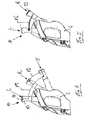
- FIGS. 4 and 5 the operating concept of an actuating device 10 according to the invention is shown.
- the FIG. 4 shows the movement of the hand lever 13 when the brake is applied from the release position to the braking position and the FIG. 5 the movement of the hand lever 13 when pressing the brake from the braking position to the release position shows.
- the operation of the brake from the release position to the braking position corresponds to that in the FIG. 2 shown procedure.
- the rest position of the hand lever 12 located in the brake position brake is analogous to the FIG. 2 between the release position L and the brake position B and is selected such that the hand lever 13 does not constitute a limitation of the foot space or the leg room, in particular at the level of the knee, an operator located in the driver's workplace or entering or exiting.
- the release of the brake without a renewed pivoting and pressing the hand lever 13 in the braking position B allows and thus enables the release of the brake at befindlichem in the rest position R hand lever 13.
- the locking element holding the driver element in the braking position is detachable when the hand lever 13 is in the rest position R, and after releasing the locking device, the driver element can be actuated in the direction of the release position.
- a manually operable actuating means 15 is to be actuated when the hand lever 13 is in the rest position in order to release the locking device holding the driver element in the braking position.
- the actuating means 15 is according to the FIG. 1 preferably formed by an arranged on the hand lever 13 operating knob.
- the driver element After actuation of the actuating means 15, the driver element is actuated by the braking position in contact with the rest position R located in the hand lever 13, so that by subsequent pivoting back of the hand lever 13 from the rest position R in the release position L - FIG. 5 is illustrated by the arrow P6 - the driver element is also operated in the release position and the brake is released.
- a locking mechanism which prevents actuation of the hand lever 13 in the direction of the braking position B when the rest position R is in the hand position and permits only actuation of the hand lever 13 from the rest position R to the release position L in that, with the rest position R of the hand lever 13, there is a single defined and clear position of the hand lever 13, in which the brake can be released.
Landscapes
- Engineering & Computer Science (AREA)
- Transportation (AREA)
- Mechanical Engineering (AREA)
- Braking Elements And Transmission Devices (AREA)
Description
- Die Erfindung betrifft ein Betätigungseinrichtung für eine manuell betätigbare Bremse, insbesondere Feststellbremse, eines Fahrzeugs, insbesondere eines Flurförderzeugs, mit einem schwenkbar gelagerten Betätigungshebel, der mittels eines Übertragungsmittels mit der Bremse in Wirkverbindung steht, wobei der Betätigungshebel einen Handhebel und ein mittels des Handhebels betätigbares Mitnehmerelement aufweist, wobei das Mitnehmerelement mit dem Übertragungsmittel in Verbindung steht, wobei zum Betätigen der Bremse in eine Bremsstellung der Handhebel von einer Lösestellung in eine Bremsstellung betätigbar ist, um das Mitnehmerelement in eine Bremsstellung zur Betätigung der Bremse zu betätigen, und wobei bei in einer Bremsstellung befindlichem Mitnehmerelement der Handhebel in eine Ruhestellung bewegbar ist.
- Derartige Betätigungseinrichtungen für die Feststellbremse eines Flurförderzeugs, insbesondere eines Gegengewichtsgabelstaplers, können seitlich neben einem Fahrerarbeitsplatz, beispielsweise einem Fahrersitz, auf einer Motor- oder Batteriehaube angeordnet sein. Alternativ kann die Betätigungseinrichtung an dem vorderen Bereich des Fahrerschutzdaches, dem sogenannten Vorderaufbau, eines Gegengewichtsgabelstaplers, angeordnet werden.
- Bei der Anordnung der Betätigungseinrichtung am Vorderaufbau des Flurförderzeugs ragt der Betätigungshebel in der Lösestellung oder der Bremsstellung in den Bereich des Fahrerarbeitsplatzes, beispielsweise einen Beinraum oder Fußraum des Fahrerarbeitsplatzes. Hierdurch kann es zu einer Behinderung für die Bedienperson insbesondere während des Auf- und Absteigens in bzw. aus dem Fahrerarbeitsplatz kommen. Ist an der Betätigungseinrichtung keine Feststelleinrichtung für die Bremsstellung oder Lösestellung vorgesehen, kann es bei einer zufälligen Berührung des Betätigungshebels während des Auf- bzw. Absteigens zu einem ungewollten Betätigen des Betätigungshebels und somit zu einem Betätigen oder Lösen der Feststellbremse kommen. Insbesondere bei Betätigungseinrichtungen, bei denen der Betätigungshebel in der Bremsstellung in den Fahrerarbeitsplatz hineinragt, kann durch eine zufällige Berührung des Betätigungshebels während des Auf- oder Absteigens der Bedienperson die Feststellbremse ungewollt gelöst werden.
- Um dies zu vermeiden, ist bei gattungsgemäßen Betätigungseinrichtungen bei in einer Bremsstellung befindlichem Mitnehmerelement der Handhebel in eine Ruhestellung bewegbar, so dass der Handhebel in der Bremsstellung der Bremse nicht mehr störend oder einschränkend in den Fahrerarbeitsplatz hineinragt.
- Ein zu dem Stand der Technik gehörendes Beispiel ist in
EP 1 997 700 A2 offenbart. - Eine weitere gattungsgemäße Betätigungseinrichtung ist aus der
DE 100 27 019 A1 bekannt. Die Betätigungseinrichtung weist einen Betätigungshebel auf, mittels dem ein von einem Spannhebel gebildetes Mitnehmerelement betätigbar ist. Zum Betätigen der Bremse in eine Bremsstellung ist der Betätigungshebel von einer Lösestellung (Figur 6) in eine Bremsstellung (Figur 7) betätigbar, um das Mitnehmerelement in eine Bremsstellung zur Betätigung der Bremse zu betätigen. Bei in einer Bremsstellung befindlichem Mitnehmerelement kann der Betätigungshebel wieder zurück in die Lösestellung bewegt werden (Figur 8). - Eine gattungsgemäße Betätigungseinrichtung ist aus der
US 6 016 718 bekannt. - Zum Betätigen der Bremse in die Bremsstellung wird der Handhebel der
US 6 016 718 von der Lösestellung in die Bremsstellung betätigt, wobei über eine Wirkverbindung zwischen dem Handhebel und dem Mitnehmerelement das Mitnehmerelement von der Lösestellung in die Bremsstellung betätigt wird. Über ein an dem Mitnehmerelement befestigtes Übertragungsmittel, beispielsweise ein Seil oder ein Bremsgestänge, und durch Ziehen des Übertragungsmittels wird die Bremse in die Bremsstellung betätigt. Bei in der Bremsstellung befindlichem Mitnehmerelement und Handhebel kann die Wirkverbindung zwischen dem Handhebel und dem Mitnehmerelement getrennt werden, so dass bei in der Bremsstellung befindlichem Mitnehmerelement der Handhebel in eine Ruhestellung betätigt werden kann. Zum anschließenden Lösen der Bremse ist es erforderlich, den Handhebel von der Ruhestellung wieder in die Bremsstellung zu betätigen, um die Wirkverbindung zwischen dem Handhebel und dem Mitnehmerelement erneut herstellen zu können. Anschließend kann durch ein Betätigungsmittel ein Verriegelungsmechanismus, der das Mitnehmelement in der Bremsstellung hält, gelöst werden, so dass durch Betätigen des Handhebels von der Bremsstellung in die Lösestellung das Mitnehmerelement von der Bremsstellung in die Lösestellung betätigt werden kann, um die Bremse zu lösen. Hierbei kann es erforderlich sein, durch Betätigen des Handhebels in die Bremsstellung an dem Übertragungsmittel zu ziehen, um den Verriegelungsmechanismus zu entspannen und die Bremse durch Betätigen des Betätigungsmittels lösen zu können. In der Bremsstellung der Bremse zeigt der in der Ruhestellung befindliche Handhebel einer Bedienperson des Fahrzeugs an, ob die Bremse in die Bremsstellung betätigt ist und somit angezogen ist bzw. ob die Bremse nicht angezogen ist. - Zum Lösen der Bremse ergibt sich jedoch eine ungünstige Ergonomie für die Bedienperson, da von der Bedienperson der Handhebel von der Ruhestellung in die Bremsstellung betätigt werden muss und an dem Übertragungsmittel gezogen werden muss, wodurch zum Ziehen an dem Überragungsmittel erneut eine Kraft von der Bedienperson über den Handhebel zum Lösen der Bremse aufgebracht werden muss. Zudem ist die Stellung des Handhebels, ab welcher die Bremse gelöst werden kann, nicht eindeutig und klar definiert, so dass sich Fehlbedienungen beim Lösen der Bremse ergeben können. Insgesamt ist somit der Lösevorgang zum Lösen der Bremse für die Bedienperson unkomfortabel.
- Der vorliegenden Erfindung liegt die Aufgabe zugrunde, eine Betätigungseinrichtung der eingangs genannten Gattung zur Verfügung zu stellen, bei der der Lösevorgang zum Lösen der Bremse für die Bedienperson des Fahrzeugs ergonomisch günstig und komfortabel ist.
- Diese Aufgabe wird erfindungsgemäß dadurch gelöst, dass die Ruhestellung des Handhebels als Zwischenstellung zwischen der Bremsstellung und der Lösestellung ausgebildet ist und zum Lösen der Bremse bei in der Ruhestellung befindlichem Handhebel eine das Mittelnehmerelement in der Bremsstellung haltende Verriegelungseinrichtung lösbar ist und das Mitnehmerelement in Richtung einer Lösestellung betätigbar ist.
- Bei der Erfindung ist die Ruhestellung des Handhebels als Zwischenstellung zwischen der Bremsstellung und der Lösestellung ausgebildet. In einer derartigen Ruhestellung als Ruheposition des Handhebels bei in der Bremsstellung befindlicher Bremse kann erzielt werden, dass der in der Ruhestellung befindliche Handhebel zu keiner Einschränkung des Beinraums oder des Fußraums im Fahrerarbeitsplatz bei einem Flurförderzeug führt und ein ungehinderter Aus- und Einstieg der Bedienperson aus bzw. in den Fahrerarbeitsplatz erzielbar ist. Zudem stellt eine derartige Ruhestellung des Handhebels eine eindeutige und definierte Stellung des Handhebels dar, in der die Bremse gelöst werden kann, so dass Fehlbedienungen beim Lösen der Bremse wirksam vermieden werden können. Erfindungsgemäß wird das Lösen der Bremse in die Ruhestellung des Handhebels ermöglicht und somit ohne ein erneutes Betätigen des Handhebels in die Bremsstellung. Hierdurch entfällt zum Lösen der Bremse ein erneutes Ziehen an dem Übertragungsmittel. Hierdurch ergibt sich ein verbesserter Komfort zum Lösen der Bremse mit einer günstigen Ergonomie. Weiterhin ist bei dem erfindungsgemäßen Bedienkonzept zum Lösen der Bremse ein schneller Lösevorgang der Bremse erzielbar, der den Komfort beim Lösen der Bremse weiter verbessert.
- Gemäß einer vorteilhaften Weiterbildung der Erfindung ist ein manuell betätigbares Betätigungsmittel zum Lösen der Verriegelungseinrichtung vorgesehen. Hierdurch kann von einer Bedienperson des Fahrzeugs durch Betätigung des Betätigungsmittels auf einfache Weise bei in der Ruhestellung befindlichem Handhebel die das Mitnehmerelement in der Bremsstellung haltende Verriegelungseinrichtung gelöst werden, um die Bremse zu lösen.
- Bevorzugt ist das Betätigungsmittel an dem Handhebel angeordnet. Das Betätigungsmittel kann hierbei als an dem Handhebel angeordneter Betätigungsknopf oder an dem Handhebel angeordneter Betätigungshebel ausgebildet sein.
- Hinsichtlich einer günstigen Ergonomie zum Lösen der Bremse ergeben sich weitere Vorteile, wenn gemäß einer Ausgestaltungsform der Erfindung nach der Betätigung des Betätigungsmittels und Lösen der Verriegelungseinrichtung das Mitnehmerelement von der Bremsstellung in Anlage an den in der Ruhestellung befindlichen Handhebel betätigbar ist und anschließend das Mitnehmerelement bei einer Betätigung des Handhebels von der Ruhestellung in die Lösestellung in die Lösestellung betätigbar ist. Nach der Betätigung des Betätigungsmittels wird somit das Mitnehmerelement selbsttätig in Anlage an den in der Ruhestellung befindlichen Handhebel betätigt, so dass bei einer Betätigung des Handhebel von der Ruhestellung in die Lösestellung das an dem Handhebel anliegende Mitnehmerelement mit in die Lösestellung betätigt wird.
- Besondere Vorteile ergeben sich, wenn gemäß einer Weiterbildung der Erfindung ein Sperrmechanismus vorhanden ist, der bei in der Ruhestellung befindlichem Handhebel eine Betätigung des Handhebels in Richtung der Bremsstellung verhindert. Ein derartiger Sperrmechanismus verhindert, dass der in der Ruhestellung befindliche Handhebel erneut in die Bremsstellung betätigt werden kann. Hierdurch wird die Möglichkeit von Fehlbedienungen und der Komfort beim Lösen der Bremse weiter verbessert, da mit der Ruhestellung des Handhebels nur eine einzige definierte Stellung des Handhebels vorgesehen ist, in der die Bremse gelöst werden kann.
- Besondere Vorteile ergeben sich, wenn die Betätigungseinrichtung am Vorderaufbau eines als Gegengewichtsgabelstapler ausgebildeten Flurförderzeugs angeordnet ist. In der Bremsstellung kann durch das Zurückschwenken des Handhebels in die Ruhestellung eine Behinderung der Bedienperson beim Auf- und Absteigen vermieden werden und eine hohe Beinfreiheit, insbesondere im Bereich der Knie der Bedienperson, bei in der Bremsstellung befindlicher Bremse erzielt werden.
- Weitere Vorteile und Einzelheiten der Erfindung werden anhand des in den schematischen Figuren dargestellten Ausführungsbeispiels näher erläutert. Hierbei zeigt
- Figur 1
- ein Flurförderzeug mit einer erfindungsgemäßen Betätigungseinrichtung einer Bremse,
- Figur 2
- eine Betätigungseinrichtung des Standes der Technik mit einer Verdeutlichung des Bewegungsablaufes des Handhebels beim Betätigen der Bremse in die Bremsstellung,
- Figur 3
- eine Betätigungseinrichtung des Standes der Technik mit einer Verdeutlichung des Bewegungsablaufes des Handhebels beim Betätigen der Bremse in die Lösestellung,
- Figur 4
- eine erfindungsgemäße Betätigungseinrichtung mit einer Verdeutlichung des Bewegungsablaufes des Handhebels beim Betätigen der Bremse in die Bremsstellung und
- Figur 5
- eine erfindungsgemäße Betätigungseinrichtung mit einer Verdeutlichung des Bewegungsablaufes des Handhebels beim Betätigen der Bremse in die Lösestellung.
- In der
Figur 1 ist ein als Gegengewichtsgabelstapler ausgebildetes Flurförderzeug 1 dargestellt. Innerhalb eines Fahrerschutzdaches 2 ist ein Fahrerarbeitsplatz ausgebildet, der beispielsweise einen Fahrersitz 3 umfasst. Der Fahrersitz 3 kann auf eine Batterie- oder Motorhaube 4 angeordnet sein. Im vorderen, einem Hubmast 5 zugewandten Bereich des Fahrerschutzdaches 2, dem sogenannten Vorderaufbau, ist eine Bedienkonsole 6, beispielsweise ein Armaturenbrett, angeordnet. An der Bedienkonsole 6 ist eine Lenkrad 7 und eine Betätigungseinrichtung 10 für eine beispielsweise als Feststellbremse ausgebildete manuell betätigbare Bremse angeordnet. - Die Betätigungseinrichtung 10 umfasst einen um eine Schwenkachse 11 schwenkbar gelagerten Betätigungshebel 12, der mittels eines nicht näher dargestellten Übertragungsmittels, beispielsweise eines Seils, eines Bowdenzugs oder eines Gestänges, mit der Bremse in Wirkverbindung steht. Der Betätigungshebel 12 umfasst einen von einer Bedienperson betätigbaren Handhebel 13 und ein mit dem Handhebel 13 in Wirkverbindung bringbares und mittels des Handhebels 13 betätigbares, nicht näher dargestelltes Mitnehmerelement. Das Mitnehmerelement steht mit dem Übertragungsmittel in Verbindung, das an dem Mitnehmerelement befestigt ist.
- Das Mitnehmerelement kann beispielsweise als Kniehebel ausgebildet werden, der zwei Hebelstellungen für die Bremsstellung und die Lösestellung aufweist und zwischen diesen Stellungen verschwenkbar ist. Bei einem derartigen Kniehebel kann in der Bremsstellung eine Totpunktverriegelung als Verriegelungseinrichtung vorgesehen sein, die zum Lösen der Bremse gelöst werden muss.
- Das Mitnehmerelement kann alternativ als Ratsche ausgebildet sein, die mit einer feststehenden Verzahnung zusammenwirkt und mehrere Rastpositionen als Bremsstellung aufweist. Bei einer derartigen Ratsche kann in der Bremsstellung eine mit der Verzahnung zusammenwirkende Sperrklinke als Verriegelungseinrichtung vorgesehen sein, die zum Lösen der Bremse gelöst werden muss.
- In der in der
Figur 1 dargestellten Stellung befindet sich die Betätigungseinrichtung 10 in einer Lösestellung, in der die Bremse gelöst ist. - In den
Figuren 2 und 3 ist der Bewegungsablauf einer aus einem Handhebel 13 und einem Mitnehmerelement bestehenden Betätigungseinrichtung 10 des Standes der Technik näher dargestellt, wobei dieFigur 2 den Bewegungsablauf des Handhebels 13 beim Betätigen der Bremse von der Lösestellung in die Bremsstellung und dieFigur 3 den Bewegungsablauf des Handhebels 13 beim Betätigen der Bremse von der Bremsstellung in die Lösestellung zeigt. - Zum Betätigen der Bremse in die Bremsstellung wird der Handhebel 13 von der Lösestellung L - wie durch den Pfeil P1 in der
Figur 2 verdeutlicht - in die Bremsstellung B verschwenkt. Über eine Wirkverbindung zwischen dem Handhebel 13 und dem nicht näher dargestellten Mitnehmerelement wird das Mitnehmerelement von der Lösestellung in die Bremsstellung betätigt. Über das an dem Mitnehmerelement befestigte Übertragungsmittel, beispielsweise ein Seil, ein Bowdenzug oder ein Bremsgestänge, und durch Ziehen des Übertragungsmittels wird die Bremse in die Bremsstellung betätigt. Bei in der Bremsstellung B befindlichem Mitnehmerelement und Handhebel 13 kann die Wirkverbindung zwischen dem Handhebel 13 und dem Mitnehmerelement getrennt werden, so dass bei in der Bremsstellung befindlichem Mitnehmerelement der Handhebel 13 zurück in eine Ruhestellung R verschwenkt werden kann, wie durch den Pfeil P2 verdeutlicht. Das Mitnehmerelement wird in der Lösestellung von einer nicht näher dargestellten Verriegelungseinrichtung gehalten. - Die Ruhestellung des Handhebels 12 bei in der Bremsstellung befindlicher Bremse befindet sich zwischen der Lösestellung L und der Bremsstellung B und ist derart gewählt, dass der Handhebel 13 zu keiner Einschränkung des Fußraums bzw. des Beinraums, insbesondere auf Höhe der Knie, einer in dem Fahrerarbeitsplatz befindlichen bzw. ein- oder aussteigenden Bedienperson darstellt.
- Zum anschließenden Lösen der Bremse ist es bei einer Betätigungseinrichtung 10 des Standes der Technik erforderlich, den Handhebel - wie in der
Figur 3 dargestellt ist - von der Ruhestellung R erneut in die Bremsstellung B zu betätigen, wie in derFigur 3 durch den Pfeil P3 verdeutlicht ist. Anschließend kann durch ein Betätigungsmittel 15, das - wie aus derFigur 3 mit dem Pfeil P4 ersichtlich ist - von einem längverschiebbaren Handgriff des Handhebels 12 gebildet ist, der Verriegelungsmechanismus, der das Mitnehmelement in der Bremsstellung hält, gelöst werden und die Wirkverbindung zwischen dem Handhebel 13 und dem Mitnehmerelement erneut herstellen zu können, so dass durch Betätigen des Handhebels 13 von der Bremsstellung B in die Lösestellung L - wie in derFigur 3 durch den Pfeil P5 verdeutlicht ist - das Mitnehmerelement von der Bremsstellung in die Lösestellung betätigt werden kann, um die Bremse zu lösen. Zum Lösen der Bremse kann es erforderlich sein, durch Betätigen des Handhebels 13 in die Bremsstellung B an dem Übertragungsmittel erneut zu ziehen, um den Verriegelungsmechanismus zu entspannen und die Bremse durch Betätigen des Betätigungsmittels 15 lösen zu können. - Dieses Bedienkonzept und Bewegungsablauf des Handhebels 13, bei dem zum Lösen der Bremse der Handhebel 13 erneut vollständig in die Bremsstellung B verschwenkt werden muss und von der Bedienperson an dem Handhebel 13 eine Kraft zum Spannen des Übertragungsmittels aufgebracht werden muss, ist für die Bedienperson ergonomisch ungünstig und unkomfortabel.
- Sofern das Mitnehmerelement als Ratsche ausgebildet, das mit einer feststehenden Verzahnung zusammenwirkt und in der Bremsstellung in mehreren Stellungen arretierbar ist, ergibt sich als weiterer Nachteil, dass die Stellung des Handhebels 13, in der die Bremse gelöst werden kann, nicht eindeutig und klar definiert ist.
- In den
Figuren 4 und 5 ist das Bedienkonzept einer erfindungsgemäßen Betätigungseinrichtung 10 dargestellt. DieFigur 4 zeigt den Bewegungsablauf des Handhebels 13 beim Betätigen der Bremse von der Lösestellung in die Bremsstellung und dieFigur 5 den Bewegungsablauf des Handhebels 13 beim Betätigen der Bremse von der Bremsstellung in die Lösestellung zeigt. - Die Betätigung der Bremse von der Lösestellung in die Bremsstellung entspricht dem in der
Figur 2 dargestellten Ablauf. - Zum Betätigen der Bremse in die Bremsstellung wird der Handhebel 13 von der Lösestellung L - wie durch den Pfeil P1 in der
Figur 4 verdeutlicht - in die Bremsstellung B verschwenkt. Über eine Wirkverbindung zwischen dem Handhebel 13 und dem nicht näher dargestellten Mitnehmerelement wird das Mitnehmerelement von der Lösestellung in die Bremsstellung betätigt. Über das an dem Mitnehmerelement befestigte Übertragungsmittel, beispielsweise ein Seil, ein Bowdenzug oder ein Bremsgestänge, und durch Ziehen des Übertragungsmittels wird die Bremse in die Bremsstellung betätigt. Bei in der Bremsstellung B befindlichem Mitnehmerelement und Handhebel 13 kann die Wirkverbindung zwischen dem Handhebel 13 und dem Mitnehmerelement getrennt werden, so dass bei in der Bremsstellung befindlichem Mitnehmerelement der Handhebel 13 zurück in eine Ruhestellung R verschwenkt werden kann, wie durch den Pfeil P2 verdeutlicht. Das Mitnehmerelement wird in der Lösestellung von einer nicht näher dargestellten Verriegelungseinrichtung gehalten. - Die Ruhestellung des Handhebels 12 bei in der Bremsstellung befindlicher Bremse befindet sich analog zu der
Figur 2 zwischen der Lösestellung L und der Bremsstellung B und ist derart gewählt, dass der Handhebel 13 zu keiner Einschränkung des Fußraums bzw. des Beinraums, insbesondere auf Höhe der Knie, einer in dem Fahrerarbeitsplatz befindlichen bzw. ein- oder aussteigenden Bedienperson darstellt. - Bei der erfindungsgemäßen Betätigungseinrichtung 10 wird das Lösen der Bremse ohne ein erneutes Ausschwenken und Betätigen des Handhebels 13 in die Bremsstellung B ermöglicht und somit das Lösen der Bremse bei in der Ruhestellung R befindlichem Handhebel 13 ermöglicht. Hierzu ist die das Mitnehmerelement in der Bremsstellung haltende Verriegelungseinrichtung bei in der Ruhestellung R befindlichem Handhebel 13 lösbar und nach Lösen der Verriegelungseinrichtung das Mitnehmerelement in Richtung der Lösestellung betätigbar ist.
- Hierzu ist bei in der Ruhestellung befindlichem Handhebel 13 ein manuell betätigbares Betätigungsmittel 15 zu betätigen, um die das Mitnehmerelement in der Bremsstellung haltende Verriegelungseinrichtung zu lösen. Das Betätigungsmittel 15 ist gemäß der
Figur 1 bevorzugt von einem an dem Handhebel 13 angeordneten Betätigungsknopf gebildet. - Nach der Betätigung des Betätigungsmittels 15 wird das Mitnehmerelement von der Bremsstellung in Anlage an den in der Ruhestellung R befindlichen Handhebel 13 betätigt, so dass durch anschließendes Zurückschwenken des Handhebels 13 von der Ruhestellung R in die Lösestellung L - wie in der
Figur 5 durch den Pfeil P6 verdeutlicht ist - das Mitnehmerelement ebenfalls in die Lösestellung betätigt wird und die Bremse gelöst wird. - Bei dem Bedienkonzept und Bewegungsablauf des Handhebels 13 der erfindungsgemäßen Betätigungseinrichtung 10 zum Lösen der Bremse ist das Entriegeln der Verriegelungseinrichtung des Mitnehmerelements in der Ruhestellung des Handhebels 13 ohne erneutes Betätigen des Handhebels 13 in die Bremsstellung B möglich, so dass auch das erneute Aufbringen einer Kraft zum Spannen des Übertragungsmittels und Entlasten der Verriegelungseinrichtung entfällt.
- Durch den vereinfachten Bewegungsablauf des Handhebels 13 beim Lösen der Bremse und den Entfall einer erneut aufzubringenden Kraft zum Spannen des Übertragungsmittels ist bei der erfindungsgemäßen Betätigungseinrichtung 10 eine verbesserte Ergonomie und ein verbesserter Komfort für die Bedienperson beim Lösen der Bremse erzielbar.
- Sofern gemäß einer Weiterbildung der Erfindung ein Sperrmechanismus vorhanden ist, der bei in der Ruhestellung R befindlichem Handhebel 13 eine Betätigung des Handhebels 13 in Richtung der Bremsstellung B verhindert und nur eine Betätigung des Handhebels 13 von der Ruhestellung R in die Lösestellung L zulässt, wird erzielt, dass mit der Ruhestellung R des Handhebels 13 eine einzige definierte und klare Stellung des Handhebels 13 geben ist, in der die Bremse gelöst werden kann. Hierdurch wird der Komfort für die Bedienperson beim Lösen der Bremse weiter verbessert und erhöht.
Claims (6)
- Betätigungseinrichtung (10) für eine manuell betätigbare Bremse, insbesondere Feststellbremse, eines Fahrzeugs, insbesondere eines Flurförderzeugs, mit einem schwenkbar gelagerten Betätigungshebel (12), der mittels eines Übertragungsmittels mit der Bremse in Wirkverbindung steht, wobei der Betätigungshebel (12) einen Handhebel (13) und ein mittels des Handhebels (13) betätigbares Mitnehmerelement aufweist, wobei das Mitnehmerelement mit dem Übertragungsmittel in Verbindung steht, wobei zum Betätigen der Bremse in eine Bremsstellung der Handhebel (13) von einer Lösestellung (L) in eine Bremsstellung (B) betätigbar ist, um das Mitnehmerelement in eine Bremsstellung zur Betätigung der Bremse zu betätigen, und wobei bei in einer Bremsstellung befindlichem Mitnehmerelement der Handhebel (13) in eine Ruhestellung (R) bewegbar ist, wobei die Ruhestellung (R) des Handhebels (13) als Zwischenstellung zwischen der Bremsstellung (B) und der Lösestellung (L) ausgebildet ist, dadurch gekennzeichnet, dass zum Lösen der Bremse bei in der Ruhestellung (R) befindlichem Handhebel (13) eine das Mittelnehmerelement in der Bremsstellung haltende Verriegelungseinrichtung lösbar ist und das Mitnehmerelement in Richtung einer Lösestellung betätigbar ist.
- Betätigungseinrichtung nach Anspruch 1, dadurch gekennzeichnet, dass ein manuell betätigbares Betätigungsmittel (15) zum Lösen der Verriegelungseinrichtung vorgesehen ist.
- Betätigungseinrichtung nach Anspruch 2, dadurch gekennzeichnet, dass das Betätigungsmittel (15) an dem Handhebel (13) angeordnet ist.
- Betätigungseinrichtung nach Anspruch 2 oder 3, dadurch gekennzeichnet, dass nach der Betätigung des Betätigungsmittels (15) und Lösen der Verriegelungseinrichtung das Mitnehmerelement von der Bremsstellung in Anlage an den in der Ruhestellung (R) befindlichen Handhebel (13) betätigbar ist und anschließend das Mitnehmerelement bei einer Betätigung des Handhebels (13) von der Ruhestellung (R) in die Lösestellung (L) in die Lösestellung betätigbar ist.
- Betätigungseinrichtung nach einem der Ansprüche 1 bis 4, dadurch gekennzeichnet, dass ein Sperrmechanismus vorhanden ist, der bei in der Ruhestellung (R) befindlichem Handhebel (13) eine Betätigung des Handhebels (13) in Richtung der Bremsstellung (B) verhindert.
- Flurförderzeug mit einer Betätigungseinrichtung nach einem der Ansprüche 1 bis 5, dadurch gekennzeichnet, dass die Betätigungseinrichtung (10) am Vorderaufbau (6) des als Gegengewichtsgabelstapler ausgebildeten Flurförderzeugs (1) angeordnet ist.
Applications Claiming Priority (1)
| Application Number | Priority Date | Filing Date | Title |
|---|---|---|---|
| DE201310110493 DE102013110493A1 (de) | 2013-09-23 | 2013-09-23 | Betätigungseinrichtung für eine Bremse |
Publications (4)
| Publication Number | Publication Date |
|---|---|
| EP2851247A2 EP2851247A2 (de) | 2015-03-25 |
| EP2851247A3 EP2851247A3 (de) | 2015-12-23 |
| EP2851247B1 EP2851247B1 (de) | 2018-04-04 |
| EP2851247B9 true EP2851247B9 (de) | 2018-09-05 |
Family
ID=51429157
Family Applications (1)
| Application Number | Title | Priority Date | Filing Date |
|---|---|---|---|
| EP14183115.6A Active EP2851247B9 (de) | 2013-09-23 | 2014-09-02 | Betätigungseinrichtung für eine Bremse |
Country Status (2)
| Country | Link |
|---|---|
| EP (1) | EP2851247B9 (de) |
| DE (1) | DE102013110493A1 (de) |
Family Cites Families (7)
| Publication number | Priority date | Publication date | Assignee | Title |
|---|---|---|---|---|
| DE3560701D1 (en) * | 1984-07-31 | 1987-11-05 | Knorr Bremse Ag | Hand brake control valve for braking systems, in particular of motor vehicles |
| DE3438899A1 (de) * | 1984-10-24 | 1986-04-24 | Robert Bosch Gmbh, 7000 Stuttgart | Bremsventil, insbesondere feststellbremsventil fuer nutzfahrzeug-bremsanlagen |
| GB2171495B (en) * | 1985-02-26 | 1989-01-11 | Bendix Ltd | Manually operable control valves |
| KR100199634B1 (ko) | 1996-12-30 | 1999-06-15 | 이충곤 | 작동레버를 접을 수 있는 핸드 브레이크 |
| DE19859496B4 (de) * | 1998-12-22 | 2007-03-15 | Fico Cables, S.A., Rubi | Hebeleinheit |
| DE10027019B4 (de) * | 2000-05-31 | 2006-06-14 | Daimlerchrysler Ag | Vorrichtung zum handbetätigten Spannen und Lösen einer Fahrzeugbremse mit wegschwenkbarem Betätigungshebel |
| DE102007025814A1 (de) * | 2007-06-02 | 2008-12-04 | Wabco Gmbh | Betätigungseinrichtung für eine Bremsanlage |
-
2013
- 2013-09-23 DE DE201310110493 patent/DE102013110493A1/de not_active Withdrawn
-
2014
- 2014-09-02 EP EP14183115.6A patent/EP2851247B9/de active Active
Also Published As
| Publication number | Publication date |
|---|---|
| EP2851247A2 (de) | 2015-03-25 |
| EP2851247B1 (de) | 2018-04-04 |
| EP2851247A3 (de) | 2015-12-23 |
| DE102013110493A1 (de) | 2015-03-26 |
Similar Documents
| Publication | Publication Date | Title |
|---|---|---|
| EP2786049B1 (de) | Getriebenotentriegelung | |
| EP1997700B1 (de) | Betätigungseinrichtung für eine Bremsanlage | |
| DE102014210134A1 (de) | Armauflagevorrichtung für einen Fahrzeuginnenraum | |
| DE19625497C1 (de) | Bedienelementanordnung zur Steuerung der Längs- und der Querbewegung eines Kraftfahrzeuges | |
| DE102005046318B4 (de) | Handbediengerät; Verfahren zur Bedienung des Brems- und des Gaspedals | |
| EP2851247B9 (de) | Betätigungseinrichtung für eine Bremse | |
| DE102008037813A1 (de) | Fahrzeug mit einer Vorrichtung zur Bedienung und Steuerung des Fahrzeugs | |
| DE102004028737A1 (de) | Betätigungssystem für eine Handbremse | |
| DE10254031B4 (de) | Deichsel für Handgabelhubwagen | |
| DE10141426C1 (de) | Handbremsanordnung für ein Kraftfahrzeug | |
| DE19938271A1 (de) | Pedal für ein Kraftfahrzeug, insbesondere Brems- oder Kupplungspedal | |
| EP3156683B1 (de) | Bremse mit einer notlüfteinrichtung | |
| EP1415875B1 (de) | Betätigungseinrichtung für eine Bremse | |
| EP1690820B1 (de) | Flurförderzeug mit einem Lenkgeber | |
| DE102009013116A1 (de) | Bremsbetätigungseinrichtung zur Betätigung einer Bremse einer fahrbaren Arbeitsmaschine | |
| EP0968869B1 (de) | Selbstfahrende landwirtschaftliche Erntemaschine | |
| DE102019009040A1 (de) | Fahrzeug | |
| EP1379417B1 (de) | Feststellbremse | |
| DE102011120146A1 (de) | Betätigungsvorrichtung für eineFeststellbremse | |
| DE102025000692A1 (de) | Lenkrad mit einem Hupenschalter sowie Verfahren | |
| EP2944602B1 (de) | Flurförderzeug mit einer verschwenkbaren anlehnhilfe | |
| EP3971127B1 (de) | Verfahren zur fahrzeugführung einer mobilen arbeitsmaschine und mobile arbeitsmaschine | |
| EP2004459B1 (de) | Handbremshebel | |
| EP2308729B1 (de) | Fahrzeug, insbesondere Elektrofahrzeug, mit einer elektrisch betätigten Feststellbremse | |
| DE19823860A1 (de) | Bedienhilfe für ein Kraftfahrzeug |
Legal Events
| Date | Code | Title | Description |
|---|---|---|---|
| PUAI | Public reference made under article 153(3) epc to a published international application that has entered the european phase |
Free format text: ORIGINAL CODE: 0009012 |
|
| 17P | Request for examination filed |
Effective date: 20140902 |
|
| AK | Designated contracting states |
Kind code of ref document: A2 Designated state(s): AL AT BE BG CH CY CZ DE DK EE ES FI FR GB GR HR HU IE IS IT LI LT LU LV MC MK MT NL NO PL PT RO RS SE SI SK SM TR |
|
| AX | Request for extension of the european patent |
Extension state: BA ME |
|
| PUAL | Search report despatched |
Free format text: ORIGINAL CODE: 0009013 |
|
| AK | Designated contracting states |
Kind code of ref document: A3 Designated state(s): AL AT BE BG CH CY CZ DE DK EE ES FI FR GB GR HR HU IE IS IT LI LT LU LV MC MK MT NL NO PL PT RO RS SE SI SK SM TR |
|
| AX | Request for extension of the european patent |
Extension state: BA ME |
|
| RIC1 | Information provided on ipc code assigned before grant |
Ipc: B60T 7/10 20060101AFI20151119BHEP |
|
| R17P | Request for examination filed (corrected) |
Effective date: 20160531 |
|
| RBV | Designated contracting states (corrected) |
Designated state(s): AL AT BE BG CH CY CZ DE DK EE ES FI FR GB GR HR HU IE IS IT LI LT LU LV MC MK MT NL NO PL PT RO RS SE SI SK SM TR |
|
| GRAP | Despatch of communication of intention to grant a patent |
Free format text: ORIGINAL CODE: EPIDOSNIGR1 |
|
| STAA | Information on the status of an ep patent application or granted ep patent |
Free format text: STATUS: GRANT OF PATENT IS INTENDED |
|
| INTG | Intention to grant announced |
Effective date: 20171006 |
|
| GRAJ | Information related to disapproval of communication of intention to grant by the applicant or resumption of examination proceedings by the epo deleted |
Free format text: ORIGINAL CODE: EPIDOSDIGR1 |
|
| STAA | Information on the status of an ep patent application or granted ep patent |
Free format text: STATUS: REQUEST FOR EXAMINATION WAS MADE |
|
| INTC | Intention to grant announced (deleted) | ||
| GRAP | Despatch of communication of intention to grant a patent |
Free format text: ORIGINAL CODE: EPIDOSNIGR1 |
|
| STAA | Information on the status of an ep patent application or granted ep patent |
Free format text: STATUS: GRANT OF PATENT IS INTENDED |
|
| INTG | Intention to grant announced |
Effective date: 20180123 |
|
| GRAS | Grant fee paid |
Free format text: ORIGINAL CODE: EPIDOSNIGR3 |
|
| GRAA | (expected) grant |
Free format text: ORIGINAL CODE: 0009210 |
|
| STAA | Information on the status of an ep patent application or granted ep patent |
Free format text: STATUS: THE PATENT HAS BEEN GRANTED |
|
| AK | Designated contracting states |
Kind code of ref document: B1 Designated state(s): AL AT BE BG CH CY CZ DE DK EE ES FI FR GB GR HR HU IE IS IT LI LT LU LV MC MK MT NL NO PL PT RO RS SE SI SK SM TR |
|
| REG | Reference to a national code |
Ref country code: GB Ref legal event code: FG4D Free format text: NOT ENGLISH |
|
| REG | Reference to a national code |
Ref country code: CH Ref legal event code: EP |
|
| REG | Reference to a national code |
Ref country code: AT Ref legal event code: REF Ref document number: 985261 Country of ref document: AT Kind code of ref document: T Effective date: 20180415 |
|
| REG | Reference to a national code |
Ref country code: DE Ref legal event code: R096 Ref document number: 502014007823 Country of ref document: DE |
|
| REG | Reference to a national code |
Ref country code: IE Ref legal event code: FG4D Free format text: LANGUAGE OF EP DOCUMENT: GERMAN |
|
| REG | Reference to a national code |
Ref country code: NL Ref legal event code: MP Effective date: 20180404 |
|
| REG | Reference to a national code |
Ref country code: CH Ref legal event code: PK Free format text: BERICHTIGUNG B9 |
|
| REG | Reference to a national code |
Ref country code: LT Ref legal event code: MG4D |
|
| PG25 | Lapsed in a contracting state [announced via postgrant information from national office to epo] |
Ref country code: NL Free format text: LAPSE BECAUSE OF FAILURE TO SUBMIT A TRANSLATION OF THE DESCRIPTION OR TO PAY THE FEE WITHIN THE PRESCRIBED TIME-LIMIT Effective date: 20180404 |
|
| PG25 | Lapsed in a contracting state [announced via postgrant information from national office to epo] |
Ref country code: BG Free format text: LAPSE BECAUSE OF FAILURE TO SUBMIT A TRANSLATION OF THE DESCRIPTION OR TO PAY THE FEE WITHIN THE PRESCRIBED TIME-LIMIT Effective date: 20180704 Ref country code: ES Free format text: LAPSE BECAUSE OF FAILURE TO SUBMIT A TRANSLATION OF THE DESCRIPTION OR TO PAY THE FEE WITHIN THE PRESCRIBED TIME-LIMIT Effective date: 20180404 Ref country code: LT Free format text: LAPSE BECAUSE OF FAILURE TO SUBMIT A TRANSLATION OF THE DESCRIPTION OR TO PAY THE FEE WITHIN THE PRESCRIBED TIME-LIMIT Effective date: 20180404 Ref country code: PL Free format text: LAPSE BECAUSE OF FAILURE TO SUBMIT A TRANSLATION OF THE DESCRIPTION OR TO PAY THE FEE WITHIN THE PRESCRIBED TIME-LIMIT Effective date: 20180404 Ref country code: NO Free format text: LAPSE BECAUSE OF FAILURE TO SUBMIT A TRANSLATION OF THE DESCRIPTION OR TO PAY THE FEE WITHIN THE PRESCRIBED TIME-LIMIT Effective date: 20180704 Ref country code: FI Free format text: LAPSE BECAUSE OF FAILURE TO SUBMIT A TRANSLATION OF THE DESCRIPTION OR TO PAY THE FEE WITHIN THE PRESCRIBED TIME-LIMIT Effective date: 20180404 Ref country code: SE Free format text: LAPSE BECAUSE OF FAILURE TO SUBMIT A TRANSLATION OF THE DESCRIPTION OR TO PAY THE FEE WITHIN THE PRESCRIBED TIME-LIMIT Effective date: 20180404 Ref country code: AL Free format text: LAPSE BECAUSE OF FAILURE TO SUBMIT A TRANSLATION OF THE DESCRIPTION OR TO PAY THE FEE WITHIN THE PRESCRIBED TIME-LIMIT Effective date: 20180404 |
|
| PG25 | Lapsed in a contracting state [announced via postgrant information from national office to epo] |
Ref country code: RS Free format text: LAPSE BECAUSE OF FAILURE TO SUBMIT A TRANSLATION OF THE DESCRIPTION OR TO PAY THE FEE WITHIN THE PRESCRIBED TIME-LIMIT Effective date: 20180404 Ref country code: GR Free format text: LAPSE BECAUSE OF FAILURE TO SUBMIT A TRANSLATION OF THE DESCRIPTION OR TO PAY THE FEE WITHIN THE PRESCRIBED TIME-LIMIT Effective date: 20180705 Ref country code: HR Free format text: LAPSE BECAUSE OF FAILURE TO SUBMIT A TRANSLATION OF THE DESCRIPTION OR TO PAY THE FEE WITHIN THE PRESCRIBED TIME-LIMIT Effective date: 20180404 Ref country code: LV Free format text: LAPSE BECAUSE OF FAILURE TO SUBMIT A TRANSLATION OF THE DESCRIPTION OR TO PAY THE FEE WITHIN THE PRESCRIBED TIME-LIMIT Effective date: 20180404 |
|
| PG25 | Lapsed in a contracting state [announced via postgrant information from national office to epo] |
Ref country code: PT Free format text: LAPSE BECAUSE OF FAILURE TO SUBMIT A TRANSLATION OF THE DESCRIPTION OR TO PAY THE FEE WITHIN THE PRESCRIBED TIME-LIMIT Effective date: 20180806 |
|
| REG | Reference to a national code |
Ref country code: DE Ref legal event code: R097 Ref document number: 502014007823 Country of ref document: DE |
|
| PG25 | Lapsed in a contracting state [announced via postgrant information from national office to epo] |
Ref country code: SK Free format text: LAPSE BECAUSE OF FAILURE TO SUBMIT A TRANSLATION OF THE DESCRIPTION OR TO PAY THE FEE WITHIN THE PRESCRIBED TIME-LIMIT Effective date: 20180404 Ref country code: RO Free format text: LAPSE BECAUSE OF FAILURE TO SUBMIT A TRANSLATION OF THE DESCRIPTION OR TO PAY THE FEE WITHIN THE PRESCRIBED TIME-LIMIT Effective date: 20180404 Ref country code: CZ Free format text: LAPSE BECAUSE OF FAILURE TO SUBMIT A TRANSLATION OF THE DESCRIPTION OR TO PAY THE FEE WITHIN THE PRESCRIBED TIME-LIMIT Effective date: 20180404 Ref country code: DK Free format text: LAPSE BECAUSE OF FAILURE TO SUBMIT A TRANSLATION OF THE DESCRIPTION OR TO PAY THE FEE WITHIN THE PRESCRIBED TIME-LIMIT Effective date: 20180404 Ref country code: EE Free format text: LAPSE BECAUSE OF FAILURE TO SUBMIT A TRANSLATION OF THE DESCRIPTION OR TO PAY THE FEE WITHIN THE PRESCRIBED TIME-LIMIT Effective date: 20180404 |
|
| PLBE | No opposition filed within time limit |
Free format text: ORIGINAL CODE: 0009261 |
|
| STAA | Information on the status of an ep patent application or granted ep patent |
Free format text: STATUS: NO OPPOSITION FILED WITHIN TIME LIMIT |
|
| PG25 | Lapsed in a contracting state [announced via postgrant information from national office to epo] |
Ref country code: SM Free format text: LAPSE BECAUSE OF FAILURE TO SUBMIT A TRANSLATION OF THE DESCRIPTION OR TO PAY THE FEE WITHIN THE PRESCRIBED TIME-LIMIT Effective date: 20180404 Ref country code: IT Free format text: LAPSE BECAUSE OF FAILURE TO SUBMIT A TRANSLATION OF THE DESCRIPTION OR TO PAY THE FEE WITHIN THE PRESCRIBED TIME-LIMIT Effective date: 20180404 |
|
| 26N | No opposition filed |
Effective date: 20190107 |
|
| PG25 | Lapsed in a contracting state [announced via postgrant information from national office to epo] |
Ref country code: MC Free format text: LAPSE BECAUSE OF FAILURE TO SUBMIT A TRANSLATION OF THE DESCRIPTION OR TO PAY THE FEE WITHIN THE PRESCRIBED TIME-LIMIT Effective date: 20180404 |
|
| REG | Reference to a national code |
Ref country code: CH Ref legal event code: PL |
|
| GBPC | Gb: european patent ceased through non-payment of renewal fee |
Effective date: 20180902 |
|
| PG25 | Lapsed in a contracting state [announced via postgrant information from national office to epo] |
Ref country code: SI Free format text: LAPSE BECAUSE OF FAILURE TO SUBMIT A TRANSLATION OF THE DESCRIPTION OR TO PAY THE FEE WITHIN THE PRESCRIBED TIME-LIMIT Effective date: 20180404 |
|
| REG | Reference to a national code |
Ref country code: BE Ref legal event code: MM Effective date: 20180930 |
|
| REG | Reference to a national code |
Ref country code: IE Ref legal event code: MM4A |
|
| PG25 | Lapsed in a contracting state [announced via postgrant information from national office to epo] |
Ref country code: LU Free format text: LAPSE BECAUSE OF NON-PAYMENT OF DUE FEES Effective date: 20180902 |
|
| PG25 | Lapsed in a contracting state [announced via postgrant information from national office to epo] |
Ref country code: IE Free format text: LAPSE BECAUSE OF NON-PAYMENT OF DUE FEES Effective date: 20180902 |
|
| PG25 | Lapsed in a contracting state [announced via postgrant information from national office to epo] |
Ref country code: CH Free format text: LAPSE BECAUSE OF NON-PAYMENT OF DUE FEES Effective date: 20180930 Ref country code: BE Free format text: LAPSE BECAUSE OF NON-PAYMENT OF DUE FEES Effective date: 20180930 Ref country code: LI Free format text: LAPSE BECAUSE OF NON-PAYMENT OF DUE FEES Effective date: 20180930 Ref country code: FR Free format text: LAPSE BECAUSE OF NON-PAYMENT OF DUE FEES Effective date: 20180930 |
|
| PG25 | Lapsed in a contracting state [announced via postgrant information from national office to epo] |
Ref country code: GB Free format text: LAPSE BECAUSE OF NON-PAYMENT OF DUE FEES Effective date: 20180902 |
|
| PG25 | Lapsed in a contracting state [announced via postgrant information from national office to epo] |
Ref country code: MT Free format text: LAPSE BECAUSE OF FAILURE TO SUBMIT A TRANSLATION OF THE DESCRIPTION OR TO PAY THE FEE WITHIN THE PRESCRIBED TIME-LIMIT Effective date: 20180404 |
|
| PG25 | Lapsed in a contracting state [announced via postgrant information from national office to epo] |
Ref country code: TR Free format text: LAPSE BECAUSE OF FAILURE TO SUBMIT A TRANSLATION OF THE DESCRIPTION OR TO PAY THE FEE WITHIN THE PRESCRIBED TIME-LIMIT Effective date: 20180404 |
|
| PG25 | Lapsed in a contracting state [announced via postgrant information from national office to epo] |
Ref country code: HU Free format text: LAPSE BECAUSE OF FAILURE TO SUBMIT A TRANSLATION OF THE DESCRIPTION OR TO PAY THE FEE WITHIN THE PRESCRIBED TIME-LIMIT; INVALID AB INITIO Effective date: 20140902 |
|
| PG25 | Lapsed in a contracting state [announced via postgrant information from national office to epo] |
Ref country code: CY Free format text: LAPSE BECAUSE OF FAILURE TO SUBMIT A TRANSLATION OF THE DESCRIPTION OR TO PAY THE FEE WITHIN THE PRESCRIBED TIME-LIMIT Effective date: 20180404 Ref country code: MK Free format text: LAPSE BECAUSE OF NON-PAYMENT OF DUE FEES Effective date: 20180404 |
|
| PG25 | Lapsed in a contracting state [announced via postgrant information from national office to epo] |
Ref country code: IS Free format text: LAPSE BECAUSE OF FAILURE TO SUBMIT A TRANSLATION OF THE DESCRIPTION OR TO PAY THE FEE WITHIN THE PRESCRIBED TIME-LIMIT Effective date: 20180804 |
|
| REG | Reference to a national code |
Ref country code: AT Ref legal event code: MM01 Ref document number: 985261 Country of ref document: AT Kind code of ref document: T Effective date: 20190902 |
|
| PG25 | Lapsed in a contracting state [announced via postgrant information from national office to epo] |
Ref country code: AT Free format text: LAPSE BECAUSE OF NON-PAYMENT OF DUE FEES Effective date: 20190902 |
|
| PGFP | Annual fee paid to national office [announced via postgrant information from national office to epo] |
Ref country code: DE Payment date: 20250919 Year of fee payment: 12 |