EP1414055B1 - Multifunction operation unit - Google Patents
Multifunction operation unit Download PDFInfo
- Publication number
- EP1414055B1 EP1414055B1 EP03256388A EP03256388A EP1414055B1 EP 1414055 B1 EP1414055 B1 EP 1414055B1 EP 03256388 A EP03256388 A EP 03256388A EP 03256388 A EP03256388 A EP 03256388A EP 1414055 B1 EP1414055 B1 EP 1414055B1
- Authority
- EP
- European Patent Office
- Prior art keywords
- operation unit
- knob
- main body
- multifunction
- display
- Prior art date
- Legal status (The legal status is an assumption and is not a legal conclusion. Google has not performed a legal analysis and makes no representation as to the accuracy of the status listed.)
- Expired - Lifetime
Links
- 238000005286 illumination Methods 0.000 claims description 3
- 230000002093 peripheral effect Effects 0.000 description 4
- 230000003287 optical effect Effects 0.000 description 3
- 238000000034 method Methods 0.000 description 1
- 238000012986 modification Methods 0.000 description 1
- 230000004048 modification Effects 0.000 description 1
Images


Classifications
-
- H—ELECTRICITY
- H01—ELECTRIC ELEMENTS
- H01H—ELECTRIC SWITCHES; RELAYS; SELECTORS; EMERGENCY PROTECTIVE DEVICES
- H01H9/00—Details of switching devices, not covered by groups H01H1/00 - H01H7/00
- H01H9/18—Distinguishing marks on switches, e.g. for indicating switch location in the dark; Adaptation of switches to receive distinguishing marks
-
- H—ELECTRICITY
- H01—ELECTRIC ELEMENTS
- H01H—ELECTRIC SWITCHES; RELAYS; SELECTORS; EMERGENCY PROTECTIVE DEVICES
- H01H25/00—Switches with compound movement of handle or other operating part
- H01H25/04—Operating part movable angularly in more than one plane, e.g. joystick
- H01H25/041—Operating part movable angularly in more than one plane, e.g. joystick having a generally flat operating member depressible at different locations to operate different controls
- H01H2025/043—Operating part movable angularly in more than one plane, e.g. joystick having a generally flat operating member depressible at different locations to operate different controls the operating member being rotatable around wobbling axis for additional switching functions
-
- Y—GENERAL TAGGING OF NEW TECHNOLOGICAL DEVELOPMENTS; GENERAL TAGGING OF CROSS-SECTIONAL TECHNOLOGIES SPANNING OVER SEVERAL SECTIONS OF THE IPC; TECHNICAL SUBJECTS COVERED BY FORMER USPC CROSS-REFERENCE ART COLLECTIONS [XRACs] AND DIGESTS
- Y10—TECHNICAL SUBJECTS COVERED BY FORMER USPC
- Y10T—TECHNICAL SUBJECTS COVERED BY FORMER US CLASSIFICATION
- Y10T74/00—Machine element or mechanism
- Y10T74/20—Control lever and linkage systems
- Y10T74/20576—Elements
- Y10T74/20732—Handles
- Y10T74/20834—Hand wheels
- Y10T74/2084—Knob or dial
Definitions
- the present invention relates to a multifunction operation unit.
- Figs. 1 and 2 show one example of a multifunction operation unit 100 that is conventionally well known.
- the multifunction operation unit 100 has an operation unit 103 such as an electronic component having an operation shaft 102 projecting from an operation unit main body 101 and capable of being axially rotated, and a knob 104 fixed to the operation shaft 102.
- the operation unit 103 is axially rotated by turning the knob 104 and reciprocated along the axial direction by pressing the knob 104 in a direction of the rotation shaft 102. And to indicate each function of the operation, a character or figure representing the function is displayed on the surface of the knob 104.
- the volume is adjusted by turning the knob 104 to axially rotate the operation shaft 102 (see Figs. 2A and 2B), or an audio medium such as a CD or tape is taken out of the audio apparatus by pressing the knob 104 in the direction of the operation shaft 102 to reciprocate the operation shaft 102 along the axial direction.
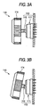
- a multifunction operation unit 110 as shown in Figs. 3A, 3B, 4A and 4B includes an operation unit 113 having an operation shaft 112 projecting from an operation unit main body 111 and capable of being axially rotated, and a knob 114 fixed to the operation shaft 112 (e.g., see JP-A-8-115641).
- the operation unit 113 is axially rotated by turning the knob 114, or tilted by pressing a peripheral portion on the surface of the knob 114 to tilt the operation shaft back or forth, left or right (up or down, and orthogonal to the paper face as seen in Figs. 3A and 3B). And a character or figure representing each function of the operation is displayed on the surface of the knob 114.
- the operation shaft 112 is axially rotated by turning the knob 114, or the operation shaft 112 is tilted in any direction, back or forth, left or right via the knob 114 (see Fig. 3B). That is, the volume is adjusted by turning the knob 114, and the volume balance of a plurality of speakers arranged around the listener is adjusted by tilting the operation shaft 112 via the knob 114.
- the function of the multifunction operation unit 100, 110 may be written on the fixing side 120 where the multifunction operation units 100 and 110 is fixed, as shown in Fig. 5, but not on the surface of the knobs 104 and 114.
- the display of the function of the operation is located away from the knobs 104 and 114, resulting in a problem that the operation of the knobs 104 and 114 is difficult to recognize.
- Such a multifunction operation unit is also disclosed in document US-A-4 131 033. It is therefore an object of the invention to provide a multifunction operation unit with an improved way of displaying a function of the operation of the multifunction operation unit by solving the problems associated with the prior art described above.
- US-A-4131033 discloses a push-pull rotating knob.
- the invention resides in a multifunction operation unit used in a state attached to a main body of an apparatus, the multifunction operation unit comprising:
- a multifunction operation unit has an operation unit main body fixed to the fixing side (a side where attached to a main body of an apparatus) and an operation shaft projecting from the operation unit main body.
- a knob is attached on the operation shaft.
- the operation shaft can be axially rotated around the shaft center, in which other operation actions including reciprocating the shaft in the axial direction and tilting the shaft are possible. That is, the operation shaft is axially rotated by turning the knob attached on the operation shaft to operate the operation unit main body and at the same time pressed or tilted via the knob to operate the operation unit main body.
- the knob is provided with a see-through part for seeing the knob through the see-through part.
- a display part is provided between the see-through part and the operation unit main body to indicate an operation action of the operation shaft.
- the display part is attached on the fixing side where the operation unit main body is fixed.
- the display part is fixed to the operation unit main body, or directly on the fixing side.
- the display part is illuminated to be easily seen.
- the display itself may be illuminated up or made luminous, or illuminated.
- the display or non-display of the display part may be selected in accordance with an operation mode of the operation unit, if needed.
- the user in operating the operation shaft via the knob to operate the operation unit main body, the user can operate the knob while seeing the content of the display on the display part through the see-through part of the knob. Since the display part is fixed to the fixing side, it is not rotated by turning the knob to axially rotate the operation shaft, and attached in a steady state at any time. Therefore, the user can accurately grasp the content of the display to operate the operation unit main body.
- a multifunction operation unit according to a first embodiment of the invention will be described below.
- the multifunction operation unit 10 as shown in Fig. 6 includes a volume switch 11 as the operation unit useful for an audio apparatus, and a knob 12 for operating the volume switch 11.
- the volume switch 11 has an operation unit main body 14 fixed to an audio apparatus main body 13 that is on the fixing side and an operation shaft 15 projecting from the operation unit main body 14.
- the knob 12 is attached to the operation shaft 15, in which it can be axially rotated around the shaft center, and reciprocated along an axial direction.
- the volume is adjusted by turning the knob 12 to axially rotate the operation shaft 15.
- other operation actions can be conducted, such as ejecting a optical disk (e.g. CD, DVD) or an audio tape from the audio apparatus, and turning on or off the power of the audio apparatus.
- a see-through part 16 that can be seen through in a direction along the operation shaft 15 is provided on a part or all of the knob 12.
- One example to provide the see-through part 16 is to form a top portion 12a of the knob 12 with a transparent or translucent member (including member that are colored), to thereby configure to see through the knob 12.
- Another example to provide the see-through part 16 is to provide an opening portion on the top portion 12a of the knob 12 to see through the knob 12.
- a display plate 17 indicating the operation content of the knob 12 as the display part is provided between the knob 12 and the operation unit main body 14.
- the display plate 17 is fixed to the audio apparatus main body 13 or the operation unit main body 14, and not rotated by turning the knob 12, as shown in Figs. 6B and 6C. Also, a character or figure representing the function of the each operation is displayed on a surface 17a of the display plate 17, as shown in Fig. 8.
- the volume is adjusted by turning the knob 12. After listening, the optical disk or the audio tape is ejected by pressing the knob 12 in the axial direction.
- the character or figure displayed on the display plate 17 is seen through the see-through part 16 of the knob 12, whereby the user can operate the knob 12 while seeing the display on the display plate 17, for example, indicating the direction for turning the knob 12 or ejecting the optical disk or the audio tape by pressing the knob 12 in the axial direction.
- the display plate 17 is fixed to the fixing side of the audio apparatus main body 13, and the display of the display plate 17 is kept unchanged and steady by turning the knob 12, whereby the display indicating other operation actions is easy to see, preventing an operation error.
- a multifunction operation unit according to a second embodiment of the invention will be described below with reference to the drawings. Parts the same as those in the first embodiment are denoted by the same reference numerals as those in the first embodiment, so that detailed description of the parts will be omitted here.
- the multifunction operation unit 20 as shown in Fig. 9 has a joy stick 21 as an electronic component for adjusting the volume balance of a plurality of speakers disposed around the listener for example, in the audio apparatus or adjusting the volume by turning a knob 22, and the knob 22 for operating the joy stick 21.
- the joy stick 21 has an operation unit main body 23 fixed to the audio apparatus main body 13 that is on the fixing side and an operation shaft 24 projecting from the operation unit main body 23.
- the knob 22 is attached to the operation shaft 24, which can be axially rotated around the shaft center.
- the operation shaft 24 can be tilted in any direction.
- the volume is adjusted by turning the knob 22 to axially rotate the operation shaft 24.
- the volume balance of the speakers is adjusted by pressing a peripheral portion on the surface of the knob 22 to tilt the operation shaft 24 back or forth, left or right.
- a display plate 25 as the display part indicating the operation content of the knob 22 is provided between the knob 22 and the operation unit main body 23.
- the display plate 25 is fixed to the audio apparatus main body 13 or the operation unit main body 23 of the joy stick 21, and not rotated or tilted by turning the knob 22 or tilting the operation shaft 24.
- a transparent see-through part 26 is provided in a part or all of the knob 22 to see the display plate 25 through the knob 22.
- the volume is adjusted by turning the knob 22 in operating the joy stick 21.
- the volume balance of the speakers is adjusted by pressing a peripheral portion on the surface of the knob 22 to tilt the operation shaft 24 back or forth, left or right.
- a character or figure displayed on the display plate 25 is seen through the see-through part 26 of for example the knob 22, whereby the user can adjust the volume by turning the knob 22 or the volume balance by moving the knob 22 back or forth, left or right to tilt the operation shaft 24 by referring to the display of the display plate 25.
- the display plate 25 is fixed to the fixing side of the audio apparatus main body 13, and the display of the display plate 25 is kept unchanged and steady by turning the knob 12, whereby the display indicating other operation actions is easy to see, preventing an operation error.
- a multifunction operation unit according to a third embodiment of the invention will be described below with reference to the drawings. Parts the same as those in the first or the second embodiment are denoted by the same reference numerals as those in the first embodiment, so that detailed description of the parts will be omitted here.
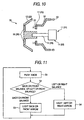
- the multifunction operation unit 30 as shown in Fig. 10 is applicable to the multifunction operation units 10 and 20 of the first and the second embodiments as described previously and shown in Figs. 6A, 6B, 6C, 9A, 9B and 9C, and has a particular characteristic in the display part.
- a display portion 31 is formed of a transparent member, and disposed opposite to the see-through part 26 of the knob 22.
- light conducting member 32 also serving as the display plate conducts a light emitted from a light emitting part 33 such as an LED to illuminate the display portion 31.
- a light emitting part 33 such as an LED
- the light conducting member 32 and the LED is provided as an illumination unit.
- the display portion for a display character or figure may be formed by an illuminant such as an LED and bonded with the display plate 25 to illuminate directly.
- the display portion 31 may be attached to the audio apparatus main body 13 that is on the fixing side or the operation unit main body 23 of the joy stick 21 that is an electronic component independently without providing the display plate 25.
- the display/non-display of the display part can be selected in accordance with an operation mode. That is, in the multifunction operation unit 20 as shown for example in Fig. 9, the operation mode can be switched by pressing the knob 22 to push in the operation shaft 24 along the axial direction, whereby the operation content corresponding to the operation mode is only displayed on the display portion 31.
- the knob 22 is pressed to select the operation mode (step S1), and when in a back or forth volume balance adjusting mode (step S2), a back or forth arrow in the display portion 31 is only illuminated (step S3) to adjust the back or forth volume balance by reciprocating the knob 22 along the axial direction, as shown in Fig. 11.
- step S2 when in a left or right volume balance adjusting mode by reciprocating the knob 22 along the axial direction (step S2), a left or right arrow in the display portion 31 is only illuminated (step S4), and the left or right volume balance is adjusted by pressing a left or right peripheral portion on the surface of the knob 22 to tilt the operation shaft left or right.
- the multifunction operation unit 30 can be operated clearly seeing the display portion 31 even when the multifunction operation unit 30 is attached in the dark place.
- the display portion 31 corresponding to the operation mode is only illuminated, preventing an operation error.
- steps S2, S3 and S4 is made by a display control unit (not shown) provided in the multifunction operation unit 30.
- the display control unit may be provided as an independent unit separate from the multifunction operation unit 30.
- a multifunction operation unit according to a fourth embodiment of the invention will be described below with reference to the drawings. Parts the same as those in the first through third embodiments are denoted by the same reference numerals as those in the first embodiment, so that detailed description of the parts will be omitted here.
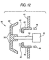
- the multifunction operation unit 40 as shown in Fig. 12 is applicable to the multifunction operation units 10 and 20 of the first and the second embodiments as described previously and shown in Figs. 6A, 6B, 6C, 9A, 9B and 9C, in which a display portion 42 is provided at a position corresponding to the see-through part 26 of the knob 22 over a panel 41 covering an electronic component.
- a display portion 42 is provided at a position corresponding to the see-through part 26 of the knob 22 over a panel 41 covering an electronic component.
- the display portion 42 is connected to a light emitting part 44 by light conducting member 43 attached on the panel 41, and lighted by causing the light emitting part 44 to emit the light.
- the display portion 42 itself may be made of an illuminant member, and attached on the panel 41 to directly illuminate the display portion 42.
- the display portion 42 is provided on the panel 41 covering the joy stick 21 that is an electronic component, whereby there is no need for providing any other member such as the display plate 25, and the number of parts is reduced.
- the multifunction operation unit 41 is attached to the audio apparatus main body 13 that is on the fixing side, it is easily treated.
- the number of parts is reduced.
- the aforementioned multifunction operation units 10, 20, 30 and 40 include the operation unit 11, 21 having the operation shaft 15, 24 projecting from the operation unit main body 14, 23 fixed to the audio apparatus main body 13 that is on the fixing side and allowing for the axial rotation and other operation actions, and the knob 12, 22 fixed to the operation shaft 15, 24 for operating the operation unit 11, 21.
- knob 12, 22 is provided with the see-through part 16, 26 that can be seen through in the direction along the operation shaft 15, 24, and the display plate 17, 25 fixed to the fixing side of the audio apparatus main body 13 is provided between the see-through part 16, 26 and the operation unit main body 14, 23.
- the display of the display plate 17, 25 is fixed not to be rotated or tilted by turning the knob 12, 22, and can be seen through the see-through part 16, 26 of the knob 12, 22, whereby the display is easy to see, preventing an operation error.
- the multifunction operation units 10, 20, 30 and 40 of the invention are not limited to the embodiments as above described, but various modifications orvariations may be adequately made thereto.
- other operation actions by the operation shaft 15, 24 include pressing the operation shaft 24 in the axial direction and tilting the operation shaft 24, but other operation actions may be further considered.
Landscapes
- Switches With Compound Operations (AREA)
- Rotary Switch, Piano Key Switch, And Lever Switch (AREA)
- Switch Cases, Indication, And Locking (AREA)
Applications Claiming Priority (2)
| Application Number | Priority Date | Filing Date | Title |
|---|---|---|---|
| JP2002306540A JP2004146090A (ja) | 2002-10-22 | 2002-10-22 | 多機能操作装置 |
| JP2002306540 | 2002-10-22 |
Publications (2)
| Publication Number | Publication Date |
|---|---|
| EP1414055A1 EP1414055A1 (en) | 2004-04-28 |
| EP1414055B1 true EP1414055B1 (en) | 2005-12-14 |
Family
ID=32064297
Family Applications (1)
| Application Number | Title | Priority Date | Filing Date |
|---|---|---|---|
| EP03256388A Expired - Lifetime EP1414055B1 (en) | 2002-10-22 | 2003-10-09 | Multifunction operation unit |
Country Status (4)
| Country | Link |
|---|---|
| US (1) | US20040074333A1 (cg-RX-API-DMAC7.html) |
| EP (1) | EP1414055B1 (cg-RX-API-DMAC7.html) |
| JP (1) | JP2004146090A (cg-RX-API-DMAC7.html) |
| DE (1) | DE60302752T2 (cg-RX-API-DMAC7.html) |
Families Citing this family (15)
| Publication number | Priority date | Publication date | Assignee | Title |
|---|---|---|---|---|
| DE102004013130B4 (de) * | 2004-03-17 | 2009-02-26 | Siemens Ag | Eingabevorrichtung zur Bedienung einer Werkzeug- oder Produktionsmaschine |
| JP4608983B2 (ja) * | 2004-07-21 | 2011-01-12 | パナソニック株式会社 | リモコン送信機及びこれを用いた送受信装置 |
| JP4504169B2 (ja) * | 2004-11-30 | 2010-07-14 | クラリオン株式会社 | コントローラ |
| DE102005017781A1 (de) * | 2005-04-17 | 2006-10-19 | Willtek Communications Gmbh | Bedienvorrichtung mit Drehrad und Taster |
| JP4530226B2 (ja) * | 2006-02-21 | 2010-08-25 | アルパイン株式会社 | ノブ |
| JP4760576B2 (ja) * | 2006-07-06 | 2011-08-31 | パナソニック株式会社 | 押圧回転操作ユニット |
| PL2090953T3 (pl) * | 2008-02-15 | 2013-05-31 | Electrolux Home Products Corp Nv | Pokrętło sterujące |
| JP5241409B2 (ja) * | 2008-09-26 | 2013-07-17 | キヤノン株式会社 | 携帯機器の入力装置 |
| DE102009003104A1 (de) * | 2009-05-14 | 2010-11-18 | BSH Bosch und Siemens Hausgeräte GmbH | Bedienvorrichtung für ein Hausgerät und Hausgerät, insbesondere zum Zubereiten von Lebensmitteln |
| JP2011111061A (ja) * | 2009-11-27 | 2011-06-09 | Fujitsu Ten Ltd | 車載表示システム |
| JP5626591B2 (ja) * | 2011-04-14 | 2014-11-19 | アルプス電気株式会社 | 入力装置 |
| EP2518591B1 (en) * | 2011-04-25 | 2018-05-30 | LS Automotive Technologies Co., Ltd. | Haptic steering wheel switch apparatus and haptic steering wheel switch system including the same |
| EP2518592B1 (en) | 2011-04-25 | 2017-07-26 | Daesung Electric Co., Ltd | Haptic steering wheel switch apparatus |
| USRE50165E1 (en) | 2014-11-26 | 2024-10-08 | Lg Electronics Inc. | Washer |
| KR102441746B1 (ko) * | 2017-12-22 | 2022-09-08 | 삼성전자주식회사 | 복수의 디스플레이를 이용하여 사용자 인터페이스를 제공하는 방법, 및 이를 위한 전자 장치 |
Family Cites Families (10)
| Publication number | Priority date | Publication date | Assignee | Title |
|---|---|---|---|---|
| US2853897A (en) * | 1955-03-10 | 1958-09-30 | Loewy Raymond | Extensible television controls |
| DE1274307B (de) * | 1961-11-15 | 1968-08-01 | Siemens Elektrogeraete Gmbh | Anzeigevorrichtung fuer mit drehbaren Betaetigungsgriffen ausgestattete Einstellorgane von Haushaltgeraeten, insbesondere Herden |
| GB1185015A (en) * | 1966-05-24 | 1970-03-18 | Elliott Brothers London Ltd | Electrical Control Apparatus Providing Two Independently-Operable Controls |
| US4011513A (en) * | 1975-03-20 | 1977-03-08 | Pioneer Electronic Corporation | Tuning device for a radio receiver |
| US4131033A (en) * | 1977-02-18 | 1978-12-26 | Rockwell International Corporation | Push-pull and rotating knob |
| JP2723761B2 (ja) * | 1992-07-14 | 1998-03-09 | 三菱電機株式会社 | 照光ツマミ装置 |
| FR2754106B1 (fr) * | 1996-09-30 | 1998-12-04 | Valeo Electronique | Commutateur a eclairage perfectionne pour tableau de commande d'une installation, notamment de vehicule automobile |
| DE19915990C1 (de) * | 1999-04-09 | 2000-05-25 | Preh Elektro Feinmechanik | Bedienteil für Steuerungsfunktionen |
| JP2002075107A (ja) * | 2000-08-31 | 2002-03-15 | Kenwood Corp | 操作ツマミ体および電子装置 |
| DE10044901A1 (de) * | 2000-09-12 | 2002-04-25 | Behr Hella Thermocontrol Gmbh | Bedieneinheit für eine Fahrzeugkomponente, insbesondere für eine Fahrzeug-Klimaanlage |
-
2002
- 2002-10-22 JP JP2002306540A patent/JP2004146090A/ja not_active Withdrawn
-
2003
- 2003-10-09 DE DE60302752T patent/DE60302752T2/de not_active Expired - Fee Related
- 2003-10-09 EP EP03256388A patent/EP1414055B1/en not_active Expired - Lifetime
- 2003-10-14 US US10/682,867 patent/US20040074333A1/en not_active Abandoned
Also Published As
| Publication number | Publication date |
|---|---|
| JP2004146090A (ja) | 2004-05-20 |
| DE60302752T2 (de) | 2006-06-14 |
| EP1414055A1 (en) | 2004-04-28 |
| DE60302752D1 (de) | 2006-01-19 |
| US20040074333A1 (en) | 2004-04-22 |
Similar Documents
| Publication | Publication Date | Title |
|---|---|---|
| EP1414055B1 (en) | Multifunction operation unit | |
| US6707387B2 (en) | Operating device for operating apparatus mounted on vehicle | |
| US5987793A (en) | Illuminative display device and electronic apparatus equipped with same | |
| US20060181521A1 (en) | Systems for dynamically illuminating touch sensors | |
| JPH0767008A (ja) | カメラ一体型vtrにおけるスイッチ機構 | |
| JP2006146701A (ja) | 操作入力装置及び電子機器 | |
| JPH09115376A (ja) | 車両用空調機の操作装置 | |
| JP2005044364A (ja) | ユーザコントロール入力を受け入れるためのシステムおよび方法 | |
| JP2001350561A (ja) | 少なくとも1つのセレクタを備える機能制御装置 | |
| CN101802951A (zh) | 显示装置和按键装置 | |
| EP1982252A2 (en) | Device for inputting control commands | |
| JP2006223586A (ja) | 遊技機 | |
| JP4529546B2 (ja) | パネル表示ユニット | |
| CN1952703A (zh) | 面发光装置 | |
| JP4317382B2 (ja) | 電子機器 | |
| JP2992198B2 (ja) | 液晶表示装置 | |
| JP2023134964A (ja) | 操作子及び電子楽器 | |
| JP3857861B2 (ja) | スイッチ装置 | |
| JP3620245B2 (ja) | 操作ノブの照明構造 | |
| US8164695B2 (en) | Flat panel display | |
| JP2008305761A (ja) | 照明装置、タッチセンサ装置及び電子機器 | |
| JP2002319324A (ja) | ボタン装置 | |
| JP4699049B2 (ja) | 表示装置 | |
| JP2000167240A (ja) | 携帯ゲーム機用の照明及び音響装置 | |
| KR101417059B1 (ko) | 센세이션 시스템 |
Legal Events
| Date | Code | Title | Description |
|---|---|---|---|
| PUAI | Public reference made under article 153(3) epc to a published international application that has entered the european phase |
Free format text: ORIGINAL CODE: 0009012 |
|
| AK | Designated contracting states |
Kind code of ref document: A1 Designated state(s): AT BE BG CH CY CZ DE DK EE ES FI FR GB GR HU IE IT LI LU MC NL PT RO SE SI SK TR |
|
| AX | Request for extension of the european patent |
Extension state: AL LT LV MK |
|
| 17P | Request for examination filed |
Effective date: 20041014 |
|
| AKX | Designation fees paid |
Designated state(s): DE FR GB |
|
| 17Q | First examination report despatched |
Effective date: 20041223 |
|
| GRAP | Despatch of communication of intention to grant a patent |
Free format text: ORIGINAL CODE: EPIDOSNIGR1 |
|
| GRAS | Grant fee paid |
Free format text: ORIGINAL CODE: EPIDOSNIGR3 |
|
| GRAA | (expected) grant |
Free format text: ORIGINAL CODE: 0009210 |
|
| AK | Designated contracting states |
Kind code of ref document: B1 Designated state(s): DE FR GB |
|
| REG | Reference to a national code |
Ref country code: GB Ref legal event code: FG4D |
|
| REF | Corresponds to: |
Ref document number: 60302752 Country of ref document: DE Date of ref document: 20060119 Kind code of ref document: P |
|
| ET | Fr: translation filed | ||
| PLBE | No opposition filed within time limit |
Free format text: ORIGINAL CODE: 0009261 |
|
| STAA | Information on the status of an ep patent application or granted ep patent |
Free format text: STATUS: NO OPPOSITION FILED WITHIN TIME LIMIT |
|
| 26N | No opposition filed |
Effective date: 20060915 |
|
| PGFP | Annual fee paid to national office [announced via postgrant information from national office to epo] |
Ref country code: DE Payment date: 20071004 Year of fee payment: 5 |
|
| PGFP | Annual fee paid to national office [announced via postgrant information from national office to epo] |
Ref country code: FR Payment date: 20071009 Year of fee payment: 5 Ref country code: GB Payment date: 20071003 Year of fee payment: 5 |
|
| GBPC | Gb: european patent ceased through non-payment of renewal fee |
Effective date: 20081009 |
|
| REG | Reference to a national code |
Ref country code: FR Ref legal event code: ST Effective date: 20090630 |
|
| PG25 | Lapsed in a contracting state [announced via postgrant information from national office to epo] |
Ref country code: DE Free format text: LAPSE BECAUSE OF NON-PAYMENT OF DUE FEES Effective date: 20090501 |
|
| PG25 | Lapsed in a contracting state [announced via postgrant information from national office to epo] |
Ref country code: FR Free format text: LAPSE BECAUSE OF NON-PAYMENT OF DUE FEES Effective date: 20081031 |
|
| PG25 | Lapsed in a contracting state [announced via postgrant information from national office to epo] |
Ref country code: GB Free format text: LAPSE BECAUSE OF NON-PAYMENT OF DUE FEES Effective date: 20081009 |