EP1410962A1 - Vorrichtung zum Sperren der Lenkspindel eines Kraftfahrzeugs - Google Patents
Vorrichtung zum Sperren der Lenkspindel eines Kraftfahrzeugs Download PDFInfo
- Publication number
- EP1410962A1 EP1410962A1 EP20030020419 EP03020419A EP1410962A1 EP 1410962 A1 EP1410962 A1 EP 1410962A1 EP 20030020419 EP20030020419 EP 20030020419 EP 03020419 A EP03020419 A EP 03020419A EP 1410962 A1 EP1410962 A1 EP 1410962A1
- Authority
- EP
- European Patent Office
- Prior art keywords
- locking pin
- locking
- control member
- housing
- pin
- Prior art date
- Legal status (The legal status is an assumption and is not a legal conclusion. Google has not performed a legal analysis and makes no representation as to the accuracy of the status listed.)
- Granted
Links
- 238000006073 displacement reaction Methods 0.000 claims abstract description 3
- 230000002441 reversible effect Effects 0.000 claims description 3
- 230000000903 blocking effect Effects 0.000 abstract description 19
- 230000006835 compression Effects 0.000 description 17
- 238000007906 compression Methods 0.000 description 17
- 230000000694 effects Effects 0.000 description 6
- 230000007704 transition Effects 0.000 description 3
- 239000000523 sample Substances 0.000 description 2
- 238000013475 authorization Methods 0.000 description 1
- 230000014759 maintenance of location Effects 0.000 description 1
- 238000012986 modification Methods 0.000 description 1
- 230000004048 modification Effects 0.000 description 1
Images


Classifications
-
- B—PERFORMING OPERATIONS; TRANSPORTING
- B60—VEHICLES IN GENERAL
- B60R—VEHICLES, VEHICLE FITTINGS, OR VEHICLE PARTS, NOT OTHERWISE PROVIDED FOR
- B60R25/00—Fittings or systems for preventing or indicating unauthorised use or theft of vehicles
- B60R25/01—Fittings or systems for preventing or indicating unauthorised use or theft of vehicles operating on vehicle systems or fittings, e.g. on doors, seats or windscreens
- B60R25/02—Fittings or systems for preventing or indicating unauthorised use or theft of vehicles operating on vehicle systems or fittings, e.g. on doors, seats or windscreens operating on the steering mechanism
- B60R25/021—Fittings or systems for preventing or indicating unauthorised use or theft of vehicles operating on vehicle systems or fittings, e.g. on doors, seats or windscreens operating on the steering mechanism restraining movement of the steering column or steering wheel hub, e.g. restraining means controlled by ignition switch
- B60R25/0215—Fittings or systems for preventing or indicating unauthorised use or theft of vehicles operating on vehicle systems or fittings, e.g. on doors, seats or windscreens operating on the steering mechanism restraining movement of the steering column or steering wheel hub, e.g. restraining means controlled by ignition switch using electric means, e.g. electric motors or solenoids
- B60R25/02153—Fittings or systems for preventing or indicating unauthorised use or theft of vehicles operating on vehicle systems or fittings, e.g. on doors, seats or windscreens operating on the steering mechanism restraining movement of the steering column or steering wheel hub, e.g. restraining means controlled by ignition switch using electric means, e.g. electric motors or solenoids comprising a locking member radially and linearly moved towards the steering column
-
- Y—GENERAL TAGGING OF NEW TECHNOLOGICAL DEVELOPMENTS; GENERAL TAGGING OF CROSS-SECTIONAL TECHNOLOGIES SPANNING OVER SEVERAL SECTIONS OF THE IPC; TECHNICAL SUBJECTS COVERED BY FORMER USPC CROSS-REFERENCE ART COLLECTIONS [XRACs] AND DIGESTS
- Y10—TECHNICAL SUBJECTS COVERED BY FORMER USPC
- Y10T—TECHNICAL SUBJECTS COVERED BY FORMER US CLASSIFICATION
- Y10T70/00—Locks
- Y10T70/50—Special application
- Y10T70/5611—For control and machine elements
- Y10T70/5646—Rotary shaft
- Y10T70/565—Locked stationary
- Y10T70/5655—Housing-carried lock
- Y10T70/5664—Latching bolt
-
- Y—GENERAL TAGGING OF NEW TECHNOLOGICAL DEVELOPMENTS; GENERAL TAGGING OF CROSS-SECTIONAL TECHNOLOGIES SPANNING OVER SEVERAL SECTIONS OF THE IPC; TECHNICAL SUBJECTS COVERED BY FORMER USPC CROSS-REFERENCE ART COLLECTIONS [XRACs] AND DIGESTS
- Y10—TECHNICAL SUBJECTS COVERED BY FORMER USPC
- Y10T—TECHNICAL SUBJECTS COVERED BY FORMER US CLASSIFICATION
- Y10T70/00—Locks
- Y10T70/50—Special application
- Y10T70/5889—For automotive vehicles
- Y10T70/5956—Steering mechanism with switch
Definitions
- the invention relates to a device for locking the steering spindle a motor vehicle against rotation by means of a in a housing via a back and forth rotatable control member between a blocking position and a Release position axially reciprocating locking bolt, which in the Locking position by means of a movably mounted in the housing, spring-loaded locking member is blocked, under the effect its spring load engages in a lateral recess of the locking pin and to move against the action of its spring load from the Well out cooperates with the control member of the locking pin.
- the locking member for blocking the locking pin in his Locking or blocking position against unauthorized movement in his Unlocking or release position, so that the associated motor vehicle steering spindle can be rotated is of a one-armed pivot lever formed, which at one end to one to the longitudinal axis of the locking pin parallel axis (DE-AS 1 780 563, Fig.
- Locking pin by one in the housing parallel to the locking pin axially slidably mounted retention wire or retaining pin against the Supported effect of its spring load, which at his Fuse end remove with the lock cylinder to move the Locking bolt or with the cylinder core of the lock cylinder connected locking pin control cam cooperates to Cancel the lock cylinder and, if necessary, the control cam axially move the enclosing housing part and the locking pin so that it engages under the action of its spring loading the lateral recess of the locking bolt runs (DE 31 31 558 C1, DE 92 08 698 U1).
- the locking pin is by an inside of the housing protruding retaining arm against the action of its spring load supported to then be released from the retaining arm and under the Effect of its spring load in engagement with the lateral depression of the Locking bolt to run when the provided with the retaining arm of the Housing is removed (DE 100 41 984 A1).
- the invention is based on the object, a device of the above specified type, which in a simple way at a special arrangement of the control member with respect to the locking pin always a reliable blocking of the locking pin in its blocking position guaranteed, so that he neither by bouncing nor by means of a magnet or otherwise be moved out of the locked position without authorization can, and which also allows the lifting of the blockade of Locking pin in its locked position in unauthorized removal of the Closure lid of a mounting opening of the housing in a simple manner prevent.
- the invention is particularly advantageous in locking devices for Motor vehicle steering spindles of the type realize, such as, for example DE 101 09 609 C1.
- a motor vehicle against rotation has a locking pin 2, which with a mounted on the steering shaft 1 locking sleeve 3 with locking grooves. 4 interacts.
- the steering shaft 1 and the locking sleeve 3 are of a Jacket tube 5 with a non-reproduced through hole for the Locking pin 2 enclosed.
- the locking pin 2 has a substantially rectangular cross-section and is in a channel, not shown corresponding cross section of a Housing 6 mounted axially displaceable.
- the longitudinal axis 7 of the locking pin. 2 cuts the common longitudinal axis 8 of the steering shaft 1 and of the coaxial jacket tube 5 at right angles.
- the housing 6 is on the of Steering spindle 1 and the jacket tube 5 opposite side with a through a Cover 9 sealed mounting opening 10 and provided on the jacket tube. 5 attached, as shown in FIG. 1.
- the steering shaft 1 and the jacket tube. 5 form the steering column 11 of the motor vehicle.
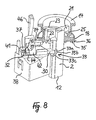
- the locking pin 2 is between the apparent from Fig. 1 to 8 blocking position, in which he with his the steering shaft 1 adjacent end 12 in a Locking groove 4 of the locking sleeve 3 engages, so that the steering shaft 1 is no longer can be rotated, and the apparent from Fig. 9 to 12 release position back and forth, in which the locking pin 2 with its end 12 in no locking groove 4 of the locking sleeve 3 engages and the steering shaft 1 releases, so that it can be turned.
- Das Control member 14 is arranged substantially coaxially with the locking pin 2, surrounds the locking pin 2 and is in the housing 6 to a longitudinal axis 7 of the Locking pin 2 parallel axis 15 between one to this axis 15th coaxial annular surface 16 of the housing 6 and one to this axis 15th coaxial ring of inner projections 17 on the closure lid 9 of Mounting opening 10 of the housing 6 rotatably mounted.
- the control member 14 is formed as a sleeve-shaped worm wheel with an outer toothing 18, in which a worm 19 which engages on the output shaft 20 of the Electric motor 13 is fixed, as shown in FIG. 2.
- the locking pin 2 is provided with two outer projections 21, 22, with which two inner inclined surfaces 23, 24 of the control member 14th interact.
- the two inclined surfaces 23, 24 have the same slope on and go respectively at its two ends in two end surfaces 25, 26 and 27, 28, which in each case in an axis of rotation 15 of the control member 14th vertical plane lie.
- a Helical compression spring 29 is arranged, which the projections 21, 22 of the Locking pin 2 against the inclined surfaces 23, 24 and the end faces 25, 26, 27, 28 of the control member 14 presses.
- the electric motor 13 is turned on, so that he the control member 14 in the clockwise direction (arrow G in Fig. 4, 7) or contrary in the clockwise direction (arrow T in Fig. 9, 12) rotates and the two projections 21, 22 of the locking pin 2 on the two inclined surfaces 23, 24 of the Control member 14 of the two steering spindle near end surfaces 25, 27 to the both steering spindle remote end surfaces 26, 28 and vice versa of the two Steering spindle remote end surfaces 26, 28 to the two steering spindle near End surfaces 25, 27 of the control member 14 run.
- the locking pin 2 is in its blocking position by means of a locking pin 30th Blockable, so that he neither by bouncing nor with the help of a magnet or by any other forces acting on it unauthorized in the direction of the arrow F (Fig. 5.6) can be moved out of the locked position, but only by turning the control member 14 in the direction of the arrow G (Fig. 4, 7). there is taken to ensure that the blockade of the locking pin 2 in his Lock position can not be canceled by the locking pin 30, when the closure lid 9 of the mounting opening 10 of the housing 6 is removed becomes.
- the locking pin 30 is mounted axially displaceably in the housing 7, wherein its longitudinal axis 31 in a longitudinal axis 7 of the locking pin second extends perpendicular plane, and that radially to the locking pin longitudinal axis. 7
- the locking pin 30 is by a helical compression spring 32 in the direction of the locking pin 2 charged to a side recess 33 of the Engage locking pin 2, and acts via a feeler 34 with a Control surface 35 of the control member 14 together to counteract the effect the helical compression spring 32 from the recess 33 of the locking pin. 2 to be moved out.
- the control surface 35 of the control member 14 extends around its axis of rotation 15 around.
- the locking pin 30 is between the control member 14 and the steering shaft. 1 arranged.
- the control surface 35 for the locking pin 30 is at the Steering spindle 1 facing end face 36 of the control member 14 is provided.
- the side arm 42 overlaps the Tastglied 34 the locking pin 30 on the guide part 38th opposite side and it engages behind a lateral projection 44 of the Securing pin 30, which at the locking bolt remote end 39 on the the probe member 34 remote from the side is provided.
- the groove 43 of Tastgliedes 34 extends parallel to the locking pin 30 and is used for recording a lateral nose 45 of a locking pin 2 parallel inner arm 46th the closure lid 9 of the mounting opening 10 of the housing. 6
- the control surface 35 consists of two to Fulcrum 15 of the control member 14 coaxial portions 35a, 35b and a Transition portion 35 c, wherein the one coaxial portion 35 a a greater distance from the control member axis of rotation 15 and has a relatively large central angle extends, the other coaxial section 35b has a smaller distance from the control member axis of rotation 15 and itself extends over a relatively small central angle and the two coaxial Sections 35a, 35b at the turning of the control member 14 in the one or other direction (arrow G or T) passing the feeler 34 Ends connected by the oblique transition portion 35c are.
- the feeler member 34 is located on the axis of rotation 15 of the Control member 14 closer coaxial portion 35b of the control surface 35, when the locking pin 2 is in its blocking position, so that according to Fig. 6, the locking pin 30 in the lateral recess 33 of the locking pin. 2 engages, in a deeper portion 33 a of the same, but without to the end 33b of the recess 33 and the lower portion 33a to extend the same.
- the feeler member 34 is located on the axis of rotation 15 of the Control member 14 further coaxial portion 35 a of the control surface 35, when the locking pin 5 assumes its release position, so that according to FIG. 11 of the locking pin 30 outside the lateral recess 33 of the Lock pin 2 is located.
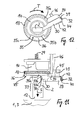
- Figs. 13, 14 illustrate that the control surface 35 of the control member 14 in With respect to the inclined surfaces 23, 24 of the control member 14 is arranged so that when turning the control member 14 from the position of FIG. 4, 7 in Direction of the arrow G first, the locking pin 30 from the side Recess 33 of the locking pin 2 and from the lower portion 33 a is pulled out of the same, namely, when the feeler 34 on Transition portion 35c along on the axis of rotation 15 of the control member 14 further coaxial portion 35 a of the control surface 35 of the control member fourteenth slides, and only then the locking pin 2 from its locked position (Fig. 5, 6, 13) in the direction of the arrow F axially into its release position (FIGS. 10, 11). is shifted, namely, when the projections 21, 22 of the locking pin 2 at slide along the inclined surfaces 23, 24 of the control member 14, while the same in the direction of the arrow G to the position shown in FIG. 9, 12 is rotated becomes.
- Figs. 15, 16 illustrate that the control member 14 then unhindered in the direction of the arrow T in the position of FIG. 4, 7, 16 can be rotated, if there is no locking groove 4 of the seated on the steering shaft 1 locking sleeve. 3 is aligned with the locking pin 2 to the free end of the 12th take.
- the locking pin 2 passes in this case in a so-called Pre-locking position, from which he by the associated helical compression spring 29 is moved further in the direction of the steering shaft 1 to its end 12 in one of the two adjacent locking grooves 4 of the locking sleeve. 3 to engage and assume its blocking position as soon as the steering spindle 1 has been rotated so that the locking groove 4 aligned with the locking pin 2 is.
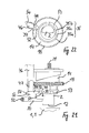
- the feeler 34 is pivoted by the arm 46 of the closure lid 9, so that the side arm 42 of the sensing member 34 from the lateral projection 44th the locking pin 30 removed and the latter by his Helical compression spring 32 is pushed axially. How very clear From Fig. 18 shows, then the side arm 42 of the sensing member 34 is not moved more behind the lateral projection 44 of the locking pin 30 be to the locking pin 30 by means of the sensing member 34 against the Effect of the helical compression spring 32 from the lower portion 33 a of to pull out lateral recess 33 of the locking pin 2. From Fig. 3 is particularly clearly seen that the locking pin 30 itself is not is accessible. He is opposite the feeler member 34 from the arm 46 of the Closing lid offset 9 away and its projection 44 is on the Tastglied 34 provided side facing away.
- the device shown in FIGS. 19 to 23 for locking the steering spindle 1 of a motor vehicle differs essentially only from those of Fig. 1 to 18, that the feeler member 34 in another way with the Locking pin 30 and the Verschlußdeckelarm 46 cooperates. That to Locking pin 30 parallel sensing member 34 is defined by the free end 47 of the Verschlußdeckelarms 46 against the action of a helical compression spring 48th held in abutment on the locking pin 30 to the latter with a nose 49 to engage behind.
- Trained as a narrow plate feeler 34 is between the free end 47 of the closure lid arm 46 and a longitudinal projection 50 of the Securing pin 30 is arranged, which on the steering shaft of the first opposite side of the locking pin 30 is provided.
- the nose 49 of the Tastgliedes 34 engages behind the control surface 35 of the control member fourteenth facing end 51 of the longitudinal projection 50.
- the through the Helical compression spring 32 loaded locking pin 30 and the on the Control surface 35 of the control member 14 adjacent probe member 34 are common under the free end 47 of the Verschlußdeckelarms 46 between the Axialgnalgna shown in FIG. 19, 20 and the axial position of FIG. 21, 22 out and ago longitudinally displaceable to the locking pin 2 in its blocking position block or cancel the blockade so that it axially into his Release order can be postponed.
Landscapes
- Engineering & Computer Science (AREA)
- Mechanical Engineering (AREA)
- Lock And Its Accessories (AREA)
- Power Steering Mechanism (AREA)
Abstract
Description
Claims (12)
- Vorrichtung zum Sperren der Lenkspindel (1) eines Kraftfahrzeugs gegen Drehen mittels eines in einem Gehäuse (6) über ein hin- und herdrehbares Steuerglied (14) zwischen einer Sperrstellung und einer Freigabestellung axial hin- und herbewegbaren Sperrbolzens (2), welcher in der Sperrstellung mit Hilfe eines im Gehäuse (6) beweglich gelagerten, federbelasteten Sicherungsgliedes blockierbar ist, das unter der Wirkung seiner Federbelastung in eine seitliche Vertiefung (33) des Sperrbolzens (2) eingreift und zur Bewegung entgegen der Wirkung seiner Federbelastung aus der Vertiefung heraus (33) mit dem Steuerglied (14) des Sperrbolzens (2) zusammenwirkt, dadurch gekennzeichnet, daßa) das Steuerglied (14) um eine mit der Längsachse (7) des Sperrbolzens (2) zusammenfallende oder zur Längsachse (7) des Sperrbolzens (2) parallele Achse (15) im Gehäuse (6) drehbar gelagert ist undb) das Sicherungsglied von einem im Gehäuse (6) axial verschieblich gelagerten Stift (30) gebildet ist, dessen Längsachse (31) in einer zur Längsachse (7) des Sperrbolzens (2) senkrechten Ebene verläuft und der unter der Wirkung seiner Federbelastung an einer Steuerfläche (35) des Steuergliedes (14) anliegt, welche sich um die Drehachse (15) des Steuergliedes (14) herum erstreckt.
- Vorrichtung nach Anspruch 1, dadurch gekennzeichnet, daß das Steuerglied (14) den Sperrbolzen (2) umschließt.
- Vorrichtung nach Anspruch 1 oder 2, dadurch gekennzeichnet, daß der Sicherungsstift (30) zwischen dem Steuerglied (14) und der Lenkspindel (1) angeordnet ist und die Steuerfläche (35) für den Sicherungsstift (30) an der der Lenkspindel (1) zugewandten Stirnseite (36) des Steuergliedes (14) vorgesehen ist.
- Vorrichtung nach Anspruch 1, 2 oder 3, gekennzeichnet durch eine solche Ausbildung der Steuerfläche (35) für den Sicherungsstift (30) am Steuerglied (14), daß beim Drehen des Steuergliedes (14) zur Axialverschiebung des Sperrbolzens (2) aus der Sperrstellung in die Freigabestellung zunächst der Sicherungsstift (30) aus der Vertiefung (33) des Sperrbolzens (2) herausbewegt wird.
- Vorrichtung nach Anspruch 1, 2, 3 oder 4, dadurch gekennzeichnet, daß die Vertiefung (33) des Sperrbolzens (2) einen tieferen Abschnitt (33a) und einen flacheren Abschnitt (33c) zur Aufnahme des Sicherungsstiftes (30) in der Sperrstellung bzw. in einer Vorsperrstellung des Sperrbolzens (2) aufweist.
- Vorrichtung nach einem der vorstehenden Ansprüche, dadurch gekennzeichnet, daß der Sicherungsstift (30) mit der Steuerfläche (35) am Steuerglied (14) über ein Tastglied (34) zusammenwirkt, an welchem ein Arm (46) eines Verschlußdeckels (9) für eine Montageöffnung (10) des Gehäuses (6) derart angreift, daß bei Entfernung des Verschlußdeckels (9) von der Montageöffnung (10) das Tastglied (34) sich außer Eingriff mit dem Sicherungsstift (30) bewegt und der Sicherungsstift (30) unter der Wirkung seiner Federbelastung bis an das Ende (33b) der Vertiefung (33) des Sperrbolzens (2) in eine Stellung läuft, in welcher das Tastglied (34) mit dem Sicherungsstift (30) , der selbst unzugänglich ist, nicht mehr im Eingriff bringbar ist.
- Vorrichtung nach Anspruch 6, dadurch gekennzeichnet, daß das Tastglied (34) parallel zum Sicherungsstift (30) angeordnet ist, einen Seitenarm (42) zum Hintergreifen eines seitlichen Vorsprungs (44) des Sicherungsstiftes (30) aufweist und mit einer zum Sicherungsstift (30) parallelen Nut (43) für den Eingriff des Arms (46) des Verschlußdeckels (9) versehen ist.
- Vorrichtung nach Anspruch 6, dadurch gekennzeichnet, daß das Tastglied (34) parallel zum Sicherungsstift (30) angeordnet ist und durch das freie Ende (47) des Arms (46) des Verschlußdeckels (9) entgegen der Wirkung einer Feder (48) in Anlage am Sicherungsstift (30) gehalten wird, um den Sicherungsstift (30) mit einer Nase (49) zu hintergreifen.
- Vorrichtung nach Anspruch 6, 7 oder 8, dadurch gekennzeichnet, daß die Montageöffnung (10) des Gehäuses (6) auf der der Lenkspindel (1) abgewandten Seite des Gehäuses (6) vorgesehen ist.
- Vorrichtung nach Anspruch 9, dadurch gekennzeichnet, daß der Arm (46) des Verschlußdeckels (9) der Montageöffnung (10) des Gehäuses (6) sich parallel zum Sperrbolzen (2) erstreckt.
- Vorrichtung nach einem der vorstehenden Ansprüche, dadurch gekennzeichnet, daß das Steuerglied (14) mittels eines Elektromotors (13) mit umkehrbarer Drehrichtung hin- und herdrehbar ist.
- Vorrichtung nach Anspruch 11, dadurch gekennzeichnet, daß der Elektromotor (13) über ein Ritzel oder eine Schnecke (19) mit dem Steuerglied (14) zusammenwirkt, welches bzw. welche in eine Außenverzahnung (18) des Steuergliedes (14) eingreift.
Applications Claiming Priority (2)
| Application Number | Priority Date | Filing Date | Title |
|---|---|---|---|
| DE10247802 | 2002-10-14 | ||
| DE10247802A DE10247802B3 (de) | 2002-10-14 | 2002-10-14 | Vorrichtung zum Sperren der Lenkspindel eines Kraftfahrzeugs |
Publications (2)
| Publication Number | Publication Date |
|---|---|
| EP1410962A1 true EP1410962A1 (de) | 2004-04-21 |
| EP1410962B1 EP1410962B1 (de) | 2005-11-16 |
Family
ID=30010638
Family Applications (1)
| Application Number | Title | Priority Date | Filing Date |
|---|---|---|---|
| EP03020419A Expired - Lifetime EP1410962B1 (de) | 2002-10-14 | 2003-09-11 | Vorrichtung zum Sperren der Lenkspindel eines Kraftfahrzeugs |
Country Status (4)
| Country | Link |
|---|---|
| US (1) | US6915671B2 (de) |
| EP (1) | EP1410962B1 (de) |
| AT (1) | ATE309931T1 (de) |
| DE (2) | DE10247802B3 (de) |
Cited By (3)
| Publication number | Priority date | Publication date | Assignee | Title |
|---|---|---|---|---|
| DE102007018218A1 (de) * | 2007-04-16 | 2008-10-23 | Huf Hülsbeck & Fürst Gmbh & Co. Kg | Vorrichtung zur Ansteuerung eines Sperrgliedes |
| DE102009033485A1 (de) * | 2009-07-15 | 2011-01-20 | Huf Hülsbeck & Fürst Gmbh & Co. Kg | Sperrvorrichtung zum Sperren eines funktionswesentlichen Bauteils eines Kraftfahrzeugs, insbesondere zur Sperrung einer Lenkspindel eines Kraftffahrzeugs |
| EP2439114A1 (de) * | 2010-10-07 | 2012-04-11 | Valeo Sicherheitssysteme | Elektrische Diebstahlsicherung zum Verriegeln/Entriegeln einer Lenksäule |
Families Citing this family (37)
| Publication number | Priority date | Publication date | Assignee | Title |
|---|---|---|---|---|
| JP3811416B2 (ja) * | 2002-03-22 | 2006-08-23 | 株式会社東海理化電機製作所 | 電動ステアリングロック装置 |
| EP1506107A4 (de) * | 2002-05-23 | 2008-11-12 | Methode Electronics Inc | Lenkschlossvorrichtung |
| DE10247803B3 (de) * | 2002-10-14 | 2004-01-29 | Huf Hülsbeck & Fürst Gmbh & Co. Kg | Vorrichtung zum Sperren der Lenkspindel eines Kraftfahrzeugs |
| JP4038132B2 (ja) * | 2003-01-31 | 2008-01-23 | 株式会社東海理化電機製作所 | 電動ステアリングロック装置 |
| JP2004231123A (ja) * | 2003-01-31 | 2004-08-19 | Tokai Rika Co Ltd | 電動ステアリングロック装置 |
| DE10320138B3 (de) * | 2003-05-06 | 2005-01-13 | Huf Hülsbeck & Fürst Gmbh & Co. Kg | Vorrichtung zum Sperren der Lenkspindel eines Kraftfahrzeugs |
| US7065993B2 (en) * | 2004-06-04 | 2006-06-27 | U-Shin Ltd. | Motor-driven steering lock device |
| DE102004031238B4 (de) * | 2004-06-29 | 2015-03-12 | Huf Hülsbeck & Fürst Gmbh & Co. Kg | Vorrichtung zum Verriegeln und/oder Entriegeln eines Lenkrades eines Kraftfahrzeugs |
| JP4496031B2 (ja) * | 2004-07-29 | 2010-07-07 | 株式会社東海理化電機製作所 | ステアリングロック装置 |
| WO2006029401A2 (en) | 2004-09-09 | 2006-03-16 | Stoneridge Control Devices, Inc. | Steering shaft lock actuator |
| DE102004043898B3 (de) * | 2004-09-10 | 2005-12-01 | Huf Hülsbeck & Fürst Gmbh & Co. Kg | Vorrichtung zum Sperren der Lenkspindel eines Kraftfahrzeugs |
| EP1637415B2 (de) | 2004-09-15 | 2019-01-09 | U-Shin Deutschland Zugangssysteme GmbH | Elektrische Vorrichtung für das Verriegeln/Entriegeln einer Lenksäule |
| JP3819925B2 (ja) * | 2004-10-29 | 2006-09-13 | 株式会社アルファ | 電動ステアリングロック装置 |
| DE102004053438A1 (de) † | 2004-11-05 | 2006-05-11 | Valeo Sicherheitssysteme Gmbh | Lenkschloß |
| US7870768B2 (en) * | 2006-10-27 | 2011-01-18 | U-Shin Ltd. | Power steering lock unit |
| JP4980853B2 (ja) * | 2006-11-10 | 2012-07-18 | 株式会社アルファ | 電動ステアリングロック装置 |
| JP5147217B2 (ja) * | 2006-11-10 | 2013-02-20 | 株式会社アルファ | ステアリングロック装置 |
| DE102007034481A1 (de) * | 2007-07-20 | 2009-01-22 | Huf Hülsbeck & Fürst Gmbh & Co. Kg | Verriegelungsvorrichtung mit Arretierungsteil |
| JP5252899B2 (ja) * | 2007-10-01 | 2013-07-31 | 株式会社アルファ | 電動ステアリングロック装置 |
| US7891221B2 (en) * | 2007-10-01 | 2011-02-22 | Alpha Corporation | Electric steering lock device |
| US7596976B2 (en) * | 2007-11-30 | 2009-10-06 | Alpha Corporation | Electric steering lock device |
| DE102007059713A1 (de) * | 2007-12-10 | 2009-06-18 | Huf Hülsbeck & Fürst Gmbh & Co. Kg | Vorrichtung zur Ansteuerung eines Sperrgliedes |
| DE102007059710B4 (de) * | 2007-12-10 | 2021-01-21 | Huf Hülsbeck & Fürst Gmbh & Co. Kg | Kompakte Verriegelungsvorrichtung mit Sicherungselement |
| DE102008016820A1 (de) * | 2008-04-01 | 2009-10-08 | Huf Hülsbeck & Fürst Gmbh & Co. Kg | Vorrichtung zur Ansteuerung einer Sperreinheit |
| JP4629751B2 (ja) * | 2008-04-09 | 2011-02-09 | 株式会社ユーシン | ステアリングロック装置 |
| JP5266070B2 (ja) * | 2009-01-13 | 2013-08-21 | 株式会社アルファ | ステアリングロック装置 |
| FR2952332B1 (fr) * | 2009-11-06 | 2013-11-29 | Valeo Securite Habitacle | Dispositif antivol pour colonne de direction de vehicule a super condamnation assuree par bascule intermediaire |
| US8424348B2 (en) * | 2010-01-27 | 2013-04-23 | Strattec Security Corporation | Steering lock |
| EP2476592B1 (de) * | 2011-01-13 | 2020-04-08 | U-Shin Deutschland Zugangssysteme GmbH | Diebstahlsicherung für Lenksäule eines Kraftfahrzeugs |
| EP2479073B1 (de) * | 2011-01-21 | 2014-01-15 | VALEO Sicherheitssysteme GmbH | Diebstahlsicherung für Lenksäule eines Kraftfahrzeugs |
| FR2984823B1 (fr) * | 2011-12-21 | 2016-01-01 | Valeo Securite Habitacle | Dispositif antivol pour colonne de direction de vehicule automobile |
| DE102013217735A1 (de) | 2012-09-07 | 2014-03-13 | Strattec Security Corporation | Lenkschloss |
| EP2716508B1 (de) * | 2012-10-04 | 2015-12-09 | U-Shin Deutschland Zugangssysteme GmbH | Elektrisches Lenksäulenschloss für ein Automobil |
| WO2014135173A1 (en) * | 2013-03-04 | 2014-09-12 | Marquardt Gmbh | Electric steering column lock system |
| US10093276B2 (en) * | 2013-10-03 | 2018-10-09 | Alpha Corporation | Steering lock device |
| US9731681B2 (en) | 2014-04-29 | 2017-08-15 | Strattec Security Corporation | Steering lock |
| DE102014112816A1 (de) | 2014-09-05 | 2016-03-10 | Huf Hülsbeck & Fürst Gmbh & Co. Kg | Lenkradverriegelung |
Citations (12)
| Publication number | Priority date | Publication date | Assignee | Title |
|---|---|---|---|---|
| DE1780563B1 (de) | 1968-09-28 | 1971-09-30 | Voss Kg J | Mit Schliesszylinder ausgeruestetes Lenkspindelschloss,insbesondere fuer Kraftfahrzeuge |
| DE3131558C1 (de) | 1981-08-08 | 1983-02-24 | Neiman Gmbh & Co Kg, 5657 Haan | Lenkschloss fuer ein Kraftfahrzeug |
| DE9208698U1 (de) | 1991-07-09 | 1992-10-01 | TRW Sipea S.p.A., Nichelino, Turin/Torino | Lenkradschloß |
| DE4436326C1 (de) * | 1994-10-11 | 1995-10-19 | Huelsbeck & Fuerst | Schloß, insbesondere zum Verriegeln der Lenkspindel oder der Zahnstange des Lenkgetriebes oder der Ausgangswelle des Antriebsgetriebes eines Kraftfahrzeugs |
| GB2298229A (en) | 1995-02-23 | 1996-08-28 | Valeo Security Systems Ltd | A lock |
| DE19653860C1 (de) | 1996-12-21 | 1998-02-26 | Valeo Gmbh & Co Schliessyst Kg | Schließsystem für Kraftfahrzeuge |
| DE10022831A1 (de) * | 2000-05-10 | 2001-12-13 | Marquardt Gmbh | Verriegelungseinrichtung, insbesondere für ein Kraftfahrzeug |
| EP1176065A2 (de) * | 2000-07-19 | 2002-01-30 | Marquardt GmbH | Verriegelungseinrichtung, insbesondere für ein Kraftfahrzeug |
| US6354117B1 (en) * | 1999-01-15 | 2002-03-12 | Valeo Securite Habitacle | Steering column anti-theft device for motor vehicle |
| DE10041984A1 (de) | 2000-08-26 | 2002-04-18 | Valeo Deutschland Gmbh & Co | Vorrichtung zur Verriegelung der Lenkspindel eines Fahrzeuges |
| DE10103182A1 (de) * | 2001-01-24 | 2002-07-25 | Valeo Sicherheitssysteme Gmbh | Verriegelungsvorrichtung |
| DE10109609C1 (de) | 2001-02-28 | 2002-10-10 | Huf Huelsbeck & Fuerst Gmbh | Schloß, insbesondere zum Verriegeln der Lenkspindel eines Kraftfahrzeugs |
Family Cites Families (7)
| Publication number | Priority date | Publication date | Assignee | Title |
|---|---|---|---|---|
| US4427967A (en) * | 1981-07-14 | 1984-01-24 | Arman S.P.A. | Electronic signaling device |
| IT1155605B (it) * | 1982-02-12 | 1987-01-28 | Champion Spark Plug Italiana | Antifurto bloccasterzo per autoveicoli |
| FR2591166B1 (fr) * | 1985-12-11 | 1988-02-12 | Neiman Sa | Antivol a securite de presence de la cle |
| DE19906267C2 (de) * | 1999-02-15 | 2001-03-15 | Valeo Deutschland Gmbh & Co | Vorrichtung zur elektrischen Verriegelung der Lenkspindel einer Kraftfahrzeug-Lenkeinrichtung |
| FR2805231B1 (fr) * | 2000-02-23 | 2002-05-10 | Valeo Securite Habitacle | Systeme d'antivol electronique perfectionne pour vehicule automobile |
| DE10030688C1 (de) * | 2000-06-23 | 2001-10-18 | Huf Huelsbeck & Fuerst Gmbh | Schloß, insbesondere zum Verriegeln der Lenkspindel oder der Zahnstange des Lenkgetriebes oder der Ausgangswelle des Antriebsgetriebes eines Kraftfahrzeugs |
| DE10039839A1 (de) * | 2000-08-10 | 2002-05-02 | Kiekert Ag | Lenkradschlosseinheiten |
-
2002
- 2002-10-14 DE DE10247802A patent/DE10247802B3/de not_active Expired - Fee Related
-
2003
- 2003-09-11 EP EP03020419A patent/EP1410962B1/de not_active Expired - Lifetime
- 2003-09-11 DE DE50301662T patent/DE50301662D1/de not_active Expired - Lifetime
- 2003-09-11 AT AT03020419T patent/ATE309931T1/de not_active IP Right Cessation
- 2003-10-10 US US10/682,208 patent/US6915671B2/en not_active Expired - Fee Related
Patent Citations (12)
| Publication number | Priority date | Publication date | Assignee | Title |
|---|---|---|---|---|
| DE1780563B1 (de) | 1968-09-28 | 1971-09-30 | Voss Kg J | Mit Schliesszylinder ausgeruestetes Lenkspindelschloss,insbesondere fuer Kraftfahrzeuge |
| DE3131558C1 (de) | 1981-08-08 | 1983-02-24 | Neiman Gmbh & Co Kg, 5657 Haan | Lenkschloss fuer ein Kraftfahrzeug |
| DE9208698U1 (de) | 1991-07-09 | 1992-10-01 | TRW Sipea S.p.A., Nichelino, Turin/Torino | Lenkradschloß |
| DE4436326C1 (de) * | 1994-10-11 | 1995-10-19 | Huelsbeck & Fuerst | Schloß, insbesondere zum Verriegeln der Lenkspindel oder der Zahnstange des Lenkgetriebes oder der Ausgangswelle des Antriebsgetriebes eines Kraftfahrzeugs |
| GB2298229A (en) | 1995-02-23 | 1996-08-28 | Valeo Security Systems Ltd | A lock |
| DE19653860C1 (de) | 1996-12-21 | 1998-02-26 | Valeo Gmbh & Co Schliessyst Kg | Schließsystem für Kraftfahrzeuge |
| US6354117B1 (en) * | 1999-01-15 | 2002-03-12 | Valeo Securite Habitacle | Steering column anti-theft device for motor vehicle |
| DE10022831A1 (de) * | 2000-05-10 | 2001-12-13 | Marquardt Gmbh | Verriegelungseinrichtung, insbesondere für ein Kraftfahrzeug |
| EP1176065A2 (de) * | 2000-07-19 | 2002-01-30 | Marquardt GmbH | Verriegelungseinrichtung, insbesondere für ein Kraftfahrzeug |
| DE10041984A1 (de) | 2000-08-26 | 2002-04-18 | Valeo Deutschland Gmbh & Co | Vorrichtung zur Verriegelung der Lenkspindel eines Fahrzeuges |
| DE10103182A1 (de) * | 2001-01-24 | 2002-07-25 | Valeo Sicherheitssysteme Gmbh | Verriegelungsvorrichtung |
| DE10109609C1 (de) | 2001-02-28 | 2002-10-10 | Huf Huelsbeck & Fuerst Gmbh | Schloß, insbesondere zum Verriegeln der Lenkspindel eines Kraftfahrzeugs |
Cited By (4)
| Publication number | Priority date | Publication date | Assignee | Title |
|---|---|---|---|---|
| DE102007018218A1 (de) * | 2007-04-16 | 2008-10-23 | Huf Hülsbeck & Fürst Gmbh & Co. Kg | Vorrichtung zur Ansteuerung eines Sperrgliedes |
| DE102009033485A1 (de) * | 2009-07-15 | 2011-01-20 | Huf Hülsbeck & Fürst Gmbh & Co. Kg | Sperrvorrichtung zum Sperren eines funktionswesentlichen Bauteils eines Kraftfahrzeugs, insbesondere zur Sperrung einer Lenkspindel eines Kraftffahrzeugs |
| EP2439114A1 (de) * | 2010-10-07 | 2012-04-11 | Valeo Sicherheitssysteme | Elektrische Diebstahlsicherung zum Verriegeln/Entriegeln einer Lenksäule |
| WO2012045808A1 (fr) * | 2010-10-07 | 2012-04-12 | Valeo Sicherheitssysteme Gmbh | Antivol electrique pour le blocage/deblocage d'une colonne de direction |
Also Published As
| Publication number | Publication date |
|---|---|
| DE50301662D1 (de) | 2005-12-22 |
| ATE309931T1 (de) | 2005-12-15 |
| US6915671B2 (en) | 2005-07-12 |
| US20040074266A1 (en) | 2004-04-22 |
| EP1410962B1 (de) | 2005-11-16 |
| DE10247802B3 (de) | 2004-02-05 |
Similar Documents
| Publication | Publication Date | Title |
|---|---|---|
| EP1410962B1 (de) | Vorrichtung zum Sperren der Lenkspindel eines Kraftfahrzeugs | |
| EP1410963B1 (de) | Vorrichtung zum Sperren der Lenkspindel eines Kraftfahrzeugs | |
| DE10030688C1 (de) | Schloß, insbesondere zum Verriegeln der Lenkspindel oder der Zahnstange des Lenkgetriebes oder der Ausgangswelle des Antriebsgetriebes eines Kraftfahrzeugs | |
| EP1363815B1 (de) | Schloss, insbesondere zum verriegeln der lenkspindel eines kraftfahrzeugs | |
| EP1236626B1 (de) | Schloss, insbesondere zum Verriegeln der Lenkspindel eines Kraftfahrzeugs | |
| DE3447748C2 (de) | ||
| DE60109697T2 (de) | Kraftfahrzeug mit voneinander unabhängigen Schwenk- und Schiebetüren | |
| EP1725437B1 (de) | Vorrichtung zum sperren der lenkspindel eines kraftfahrzeugs | |
| DE102005032474A1 (de) | Anhängevorrichtung | |
| DE19719343C1 (de) | Verriegelungsvorrichtung für ein Kraftfahrzeug | |
| DE69614587T2 (de) | Verriegelungsmechanismus für mit einem Schlüssel betätigbarer Schalter | |
| DE3439705C2 (de) | ||
| DE69003357T2 (de) | Motorisiertes Scharnier, zu öffnen, zu verschliessen, zu verriegeln und zu entriegeln. | |
| DE4407912C2 (de) | Elektromechanisches Schloß | |
| DE2136636B2 (de) | Rechts/Links durch Umwenden ver wendbares Fallennegelschloß | |
| DE19526660A1 (de) | Elektromechanisches Schloß | |
| EP3517715B1 (de) | Zuhaltung mit hilfsentriegelung | |
| DE9417227U1 (de) | Verriegelungsschloß | |
| WO2017032604A1 (de) | Getriebe für eine beschlaganordnung eines fensters, einer tür oder dergleichen | |
| DE3534523C2 (de) | Lenkradschloß | |
| CH671603A5 (de) | ||
| DE2825873B2 (de) | Kraftfahrzeug-Lenkschloß | |
| DE3224411C1 (de) | Kraftfahrzeug-Lenkschloss | |
| DE2621857B2 (de) | Lenk- und Zündschloß | |
| DE929295C (de) | Sicherungsvorrichtung gegen Diebstahl von Kraftfahrzeugen |
Legal Events
| Date | Code | Title | Description |
|---|---|---|---|
| PUAI | Public reference made under article 153(3) epc to a published international application that has entered the european phase |
Free format text: ORIGINAL CODE: 0009012 |
|
| 17P | Request for examination filed |
Effective date: 20040218 |
|
| AK | Designated contracting states |
Kind code of ref document: A1 Designated state(s): AT BE BG CH CY CZ DE DK EE ES FI FR GB GR HU IE IT LI LU MC NL PT RO SE SI SK TR |
|
| AX | Request for extension of the european patent |
Extension state: AL LT LV MK |
|
| 17Q | First examination report despatched |
Effective date: 20040810 |
|
| AKX | Designation fees paid |
Designated state(s): AT BE BG CH CY CZ DE DK EE ES FI FR GB GR HU IE IT LI LU MC NL PT RO SE SI SK TR |
|
| GRAP | Despatch of communication of intention to grant a patent |
Free format text: ORIGINAL CODE: EPIDOSNIGR1 |
|
| GRAS | Grant fee paid |
Free format text: ORIGINAL CODE: EPIDOSNIGR3 |
|
| GRAA | (expected) grant |
Free format text: ORIGINAL CODE: 0009210 |
|
| AK | Designated contracting states |
Kind code of ref document: B1 Designated state(s): AT BE BG CH CY CZ DE DK EE ES FI FR GB GR HU IE IT LI LU MC NL PT RO SE SI SK TR |
|
| PG25 | Lapsed in a contracting state [announced via postgrant information from national office to epo] |
Ref country code: SK Free format text: LAPSE BECAUSE OF FAILURE TO SUBMIT A TRANSLATION OF THE DESCRIPTION OR TO PAY THE FEE WITHIN THE PRESCRIBED TIME-LIMIT Effective date: 20051116 Ref country code: RO Free format text: LAPSE BECAUSE OF FAILURE TO SUBMIT A TRANSLATION OF THE DESCRIPTION OR TO PAY THE FEE WITHIN THE PRESCRIBED TIME-LIMIT Effective date: 20051116 Ref country code: CZ Free format text: LAPSE BECAUSE OF FAILURE TO SUBMIT A TRANSLATION OF THE DESCRIPTION OR TO PAY THE FEE WITHIN THE PRESCRIBED TIME-LIMIT Effective date: 20051116 Ref country code: NL Free format text: LAPSE BECAUSE OF FAILURE TO SUBMIT A TRANSLATION OF THE DESCRIPTION OR TO PAY THE FEE WITHIN THE PRESCRIBED TIME-LIMIT Effective date: 20051116 Ref country code: FI Free format text: LAPSE BECAUSE OF FAILURE TO SUBMIT A TRANSLATION OF THE DESCRIPTION OR TO PAY THE FEE WITHIN THE PRESCRIBED TIME-LIMIT Effective date: 20051116 Ref country code: IE Free format text: LAPSE BECAUSE OF FAILURE TO SUBMIT A TRANSLATION OF THE DESCRIPTION OR TO PAY THE FEE WITHIN THE PRESCRIBED TIME-LIMIT Effective date: 20051116 Ref country code: SI Free format text: LAPSE BECAUSE OF FAILURE TO SUBMIT A TRANSLATION OF THE DESCRIPTION OR TO PAY THE FEE WITHIN THE PRESCRIBED TIME-LIMIT Effective date: 20051116 |
|
| REG | Reference to a national code |
Ref country code: GB Ref legal event code: FG4D Free format text: NOT ENGLISH |
|
| REG | Reference to a national code |
Ref country code: CH Ref legal event code: EP |
|
| GBT | Gb: translation of ep patent filed (gb section 77(6)(a)/1977) | ||
| REF | Corresponds to: |
Ref document number: 50301662 Country of ref document: DE Date of ref document: 20051222 Kind code of ref document: P |
|
| REG | Reference to a national code |
Ref country code: IE Ref legal event code: FG4D Free format text: LANGUAGE OF EP DOCUMENT: GERMAN |
|
| PG25 | Lapsed in a contracting state [announced via postgrant information from national office to epo] |
Ref country code: BG Free format text: LAPSE BECAUSE OF FAILURE TO SUBMIT A TRANSLATION OF THE DESCRIPTION OR TO PAY THE FEE WITHIN THE PRESCRIBED TIME-LIMIT Effective date: 20060216 Ref country code: SE Free format text: LAPSE BECAUSE OF FAILURE TO SUBMIT A TRANSLATION OF THE DESCRIPTION OR TO PAY THE FEE WITHIN THE PRESCRIBED TIME-LIMIT Effective date: 20060216 Ref country code: DK Free format text: LAPSE BECAUSE OF FAILURE TO SUBMIT A TRANSLATION OF THE DESCRIPTION OR TO PAY THE FEE WITHIN THE PRESCRIBED TIME-LIMIT Effective date: 20060216 Ref country code: GR Free format text: LAPSE BECAUSE OF FAILURE TO SUBMIT A TRANSLATION OF THE DESCRIPTION OR TO PAY THE FEE WITHIN THE PRESCRIBED TIME-LIMIT Effective date: 20060216 |
|
| PG25 | Lapsed in a contracting state [announced via postgrant information from national office to epo] |
Ref country code: ES Free format text: LAPSE BECAUSE OF FAILURE TO SUBMIT A TRANSLATION OF THE DESCRIPTION OR TO PAY THE FEE WITHIN THE PRESCRIBED TIME-LIMIT Effective date: 20060227 |
|
| PG25 | Lapsed in a contracting state [announced via postgrant information from national office to epo] |
Ref country code: PT Free format text: LAPSE BECAUSE OF FAILURE TO SUBMIT A TRANSLATION OF THE DESCRIPTION OR TO PAY THE FEE WITHIN THE PRESCRIBED TIME-LIMIT Effective date: 20060417 |
|
| NLV1 | Nl: lapsed or annulled due to failure to fulfill the requirements of art. 29p and 29m of the patents act | ||
| PG25 | Lapsed in a contracting state [announced via postgrant information from national office to epo] |
Ref country code: HU Free format text: LAPSE BECAUSE OF FAILURE TO SUBMIT A TRANSLATION OF THE DESCRIPTION OR TO PAY THE FEE WITHIN THE PRESCRIBED TIME-LIMIT Effective date: 20060517 |
|
| REG | Reference to a national code |
Ref country code: IE Ref legal event code: FD4D |
|
| ET | Fr: translation filed | ||
| PLBE | No opposition filed within time limit |
Free format text: ORIGINAL CODE: 0009261 |
|
| STAA | Information on the status of an ep patent application or granted ep patent |
Free format text: STATUS: NO OPPOSITION FILED WITHIN TIME LIMIT |
|
| PG25 | Lapsed in a contracting state [announced via postgrant information from national office to epo] |
Ref country code: MC Free format text: LAPSE BECAUSE OF NON-PAYMENT OF DUE FEES Effective date: 20060930 Ref country code: BE Free format text: LAPSE BECAUSE OF NON-PAYMENT OF DUE FEES Effective date: 20060930 |
|
| 26N | No opposition filed |
Effective date: 20060817 |
|
| PG25 | Lapsed in a contracting state [announced via postgrant information from national office to epo] |
Ref country code: AT Free format text: LAPSE BECAUSE OF NON-PAYMENT OF DUE FEES Effective date: 20060911 |
|
| BERE | Be: lapsed |
Owner name: HUF HULSBECK & FURST G.M.B.H. & CO. KG Effective date: 20060930 |
|
| REG | Reference to a national code |
Ref country code: CH Ref legal event code: PL |
|
| PG25 | Lapsed in a contracting state [announced via postgrant information from national office to epo] |
Ref country code: EE Free format text: LAPSE BECAUSE OF FAILURE TO SUBMIT A TRANSLATION OF THE DESCRIPTION OR TO PAY THE FEE WITHIN THE PRESCRIBED TIME-LIMIT Effective date: 20051116 |
|
| PG25 | Lapsed in a contracting state [announced via postgrant information from national office to epo] |
Ref country code: LI Free format text: LAPSE BECAUSE OF NON-PAYMENT OF DUE FEES Effective date: 20070930 Ref country code: LU Free format text: LAPSE BECAUSE OF NON-PAYMENT OF DUE FEES Effective date: 20060911 Ref country code: TR Free format text: LAPSE BECAUSE OF FAILURE TO SUBMIT A TRANSLATION OF THE DESCRIPTION OR TO PAY THE FEE WITHIN THE PRESCRIBED TIME-LIMIT Effective date: 20051116 Ref country code: CH Free format text: LAPSE BECAUSE OF NON-PAYMENT OF DUE FEES Effective date: 20070930 |
|
| PG25 | Lapsed in a contracting state [announced via postgrant information from national office to epo] |
Ref country code: CY Free format text: LAPSE BECAUSE OF FAILURE TO SUBMIT A TRANSLATION OF THE DESCRIPTION OR TO PAY THE FEE WITHIN THE PRESCRIBED TIME-LIMIT Effective date: 20051116 |
|
| PGFP | Annual fee paid to national office [announced via postgrant information from national office to epo] |
Ref country code: IT Payment date: 20140929 Year of fee payment: 12 |
|
| PG25 | Lapsed in a contracting state [announced via postgrant information from national office to epo] |
Ref country code: IT Free format text: LAPSE BECAUSE OF NON-PAYMENT OF DUE FEES Effective date: 20150911 |
|
| REG | Reference to a national code |
Ref country code: FR Ref legal event code: PLFP Year of fee payment: 14 |
|
| REG | Reference to a national code |
Ref country code: FR Ref legal event code: PLFP Year of fee payment: 15 |
|
| PGFP | Annual fee paid to national office [announced via postgrant information from national office to epo] |
Ref country code: GB Payment date: 20170925 Year of fee payment: 15 Ref country code: FR Payment date: 20170925 Year of fee payment: 15 |
|
| GBPC | Gb: european patent ceased through non-payment of renewal fee |
Effective date: 20180911 |
|
| PG25 | Lapsed in a contracting state [announced via postgrant information from national office to epo] |
Ref country code: FR Free format text: LAPSE BECAUSE OF NON-PAYMENT OF DUE FEES Effective date: 20180930 |
|
| PG25 | Lapsed in a contracting state [announced via postgrant information from national office to epo] |
Ref country code: GB Free format text: LAPSE BECAUSE OF NON-PAYMENT OF DUE FEES Effective date: 20180911 |
|
| PGFP | Annual fee paid to national office [announced via postgrant information from national office to epo] |
Ref country code: DE Payment date: 20200924 Year of fee payment: 18 |
|
| REG | Reference to a national code |
Ref country code: DE Ref legal event code: R119 Ref document number: 50301662 Country of ref document: DE |
|
| PG25 | Lapsed in a contracting state [announced via postgrant information from national office to epo] |
Ref country code: DE Free format text: LAPSE BECAUSE OF NON-PAYMENT OF DUE FEES Effective date: 20220401 |