EP1408207A1 - Wabenkörperstruktur mit Filtereigenshaften, dessen Herstellung und Verwendung in der Abgasreinigung - Google Patents
Wabenkörperstruktur mit Filtereigenshaften, dessen Herstellung und Verwendung in der Abgasreinigung Download PDFInfo
- Publication number
- EP1408207A1 EP1408207A1 EP20030256389 EP03256389A EP1408207A1 EP 1408207 A1 EP1408207 A1 EP 1408207A1 EP 20030256389 EP20030256389 EP 20030256389 EP 03256389 A EP03256389 A EP 03256389A EP 1408207 A1 EP1408207 A1 EP 1408207A1
- Authority
- EP
- European Patent Office
- Prior art keywords
- honeycomb structure
- slit
- structure according
- exhaust gas
- slits
- Prior art date
- Legal status (The legal status is an assumption and is not a legal conclusion. Google has not performed a legal analysis and makes no representation as to the accuracy of the status listed.)
- Granted
Links
- 238000004519 manufacturing process Methods 0.000 title claims abstract description 15
- 238000000746 purification Methods 0.000 title claims abstract description 8
- 238000001914 filtration Methods 0.000 title 1
- 238000005192 partition Methods 0.000 claims abstract description 40
- 230000008929 regeneration Effects 0.000 claims abstract description 19
- 238000011069 regeneration method Methods 0.000 claims abstract description 19
- 239000012530 fluid Substances 0.000 claims abstract description 17
- 239000011236 particulate material Substances 0.000 claims abstract description 17
- 238000000034 method Methods 0.000 claims abstract description 12
- 230000008021 deposition Effects 0.000 claims abstract description 11
- 239000000428 dust Substances 0.000 claims abstract description 9
- 239000000463 material Substances 0.000 claims abstract description 7
- 238000010304 firing Methods 0.000 claims abstract description 3
- 239000002956 ash Substances 0.000 claims description 27
- 235000002918 Fraxinus excelsior Nutrition 0.000 claims description 25
- 238000002485 combustion reaction Methods 0.000 claims description 15
- 230000002093 peripheral effect Effects 0.000 claims description 10
- 239000003054 catalyst Substances 0.000 claims description 9
- 238000010438 heat treatment Methods 0.000 claims description 8
- 239000000446 fuel Substances 0.000 claims description 7
- XLYOFNOQVPJJNP-UHFFFAOYSA-N water Chemical compound O XLYOFNOQVPJJNP-UHFFFAOYSA-N 0.000 claims description 5
- OKTJSMMVPCPJKN-UHFFFAOYSA-N Carbon Chemical compound [C] OKTJSMMVPCPJKN-UHFFFAOYSA-N 0.000 claims description 4
- 229910052799 carbon Inorganic materials 0.000 claims description 4
- 229910052581 Si3N4 Inorganic materials 0.000 claims description 2
- PNEYBMLMFCGWSK-UHFFFAOYSA-N aluminium oxide Inorganic materials [O-2].[O-2].[O-2].[Al+3].[Al+3] PNEYBMLMFCGWSK-UHFFFAOYSA-N 0.000 claims description 2
- 238000006243 chemical reaction Methods 0.000 claims description 2
- 229910052878 cordierite Inorganic materials 0.000 claims description 2
- 239000013078 crystal Substances 0.000 claims description 2
- JSKIRARMQDRGJZ-UHFFFAOYSA-N dimagnesium dioxido-bis[(1-oxido-3-oxo-2,4,6,8,9-pentaoxa-1,3-disila-5,7-dialuminabicyclo[3.3.1]nonan-7-yl)oxy]silane Chemical compound [Mg++].[Mg++].[O-][Si]([O-])(O[Al]1O[Al]2O[Si](=O)O[Si]([O-])(O1)O2)O[Al]1O[Al]2O[Si](=O)O[Si]([O-])(O1)O2 JSKIRARMQDRGJZ-UHFFFAOYSA-N 0.000 claims description 2
- KZHJGOXRZJKJNY-UHFFFAOYSA-N dioxosilane;oxo(oxoalumanyloxy)alumane Chemical compound O=[Si]=O.O=[Si]=O.O=[Al]O[Al]=O.O=[Al]O[Al]=O.O=[Al]O[Al]=O KZHJGOXRZJKJNY-UHFFFAOYSA-N 0.000 claims description 2
- JEGUKCSWCFPDGT-UHFFFAOYSA-N h2o hydrate Chemical compound O.O JEGUKCSWCFPDGT-UHFFFAOYSA-N 0.000 claims description 2
- 230000001678 irradiating effect Effects 0.000 claims description 2
- 239000007788 liquid Substances 0.000 claims description 2
- 229910052863 mullite Inorganic materials 0.000 claims description 2
- HBMJWWWQQXIZIP-UHFFFAOYSA-N silicon carbide Chemical compound [Si+]#[C-] HBMJWWWQQXIZIP-UHFFFAOYSA-N 0.000 claims description 2
- 229910010271 silicon carbide Inorganic materials 0.000 claims description 2
- HQVNEWCFYHHQES-UHFFFAOYSA-N silicon nitride Chemical compound N12[Si]34N5[Si]62N3[Si]51N64 HQVNEWCFYHHQES-UHFFFAOYSA-N 0.000 claims description 2
- 230000000630 rising effect Effects 0.000 claims 1
- 241000549527 Fraxinus gooddingii Species 0.000 abstract 1
- 230000001172 regenerating effect Effects 0.000 description 8
- 210000004027 cell Anatomy 0.000 description 6
- 238000002347 injection Methods 0.000 description 5
- 239000007924 injection Substances 0.000 description 5
- 210000002421 cell wall Anatomy 0.000 description 4
- 239000000919 ceramic Substances 0.000 description 4
- 230000007423 decrease Effects 0.000 description 3
- 230000006866 deterioration Effects 0.000 description 3
- 239000004071 soot Substances 0.000 description 3
- 238000011144 upstream manufacturing Methods 0.000 description 3
- 241000220317 Rosa Species 0.000 description 2
- 238000004891 communication Methods 0.000 description 2
- JFBZPFYRPYOZCQ-UHFFFAOYSA-N [Li].[Al] Chemical compound [Li].[Al] JFBZPFYRPYOZCQ-UHFFFAOYSA-N 0.000 description 1
- 230000001133 acceleration Effects 0.000 description 1
- 238000007599 discharging Methods 0.000 description 1
- 238000006073 displacement reaction Methods 0.000 description 1
- 238000003912 environmental pollution Methods 0.000 description 1
- 229910052763 palladium Inorganic materials 0.000 description 1
- 229910052697 platinum Inorganic materials 0.000 description 1
- 238000011084 recovery Methods 0.000 description 1
- 229910052703 rhodium Inorganic materials 0.000 description 1
Images


Classifications
-
- B—PERFORMING OPERATIONS; TRANSPORTING
- B01—PHYSICAL OR CHEMICAL PROCESSES OR APPARATUS IN GENERAL
- B01D—SEPARATION
- B01D46/00—Filters or filtering processes specially modified for separating dispersed particles from gases or vapours
- B01D46/24—Particle separators, e.g. dust precipitators, using rigid hollow filter bodies
- B01D46/2403—Particle separators, e.g. dust precipitators, using rigid hollow filter bodies characterised by the physical shape or structure of the filtering element
- B01D46/2418—Honeycomb filters
- B01D46/2451—Honeycomb filters characterized by the geometrical structure, shape, pattern or configuration or parameters related to the geometry of the structure
- B01D46/247—Honeycomb filters characterized by the geometrical structure, shape, pattern or configuration or parameters related to the geometry of the structure of the cells
-
- B—PERFORMING OPERATIONS; TRANSPORTING
- B01—PHYSICAL OR CHEMICAL PROCESSES OR APPARATUS IN GENERAL
- B01D—SEPARATION
- B01D46/00—Filters or filtering processes specially modified for separating dispersed particles from gases or vapours
- B01D46/24—Particle separators, e.g. dust precipitators, using rigid hollow filter bodies
- B01D46/2403—Particle separators, e.g. dust precipitators, using rigid hollow filter bodies characterised by the physical shape or structure of the filtering element
- B01D46/2418—Honeycomb filters
- B01D46/2451—Honeycomb filters characterized by the geometrical structure, shape, pattern or configuration or parameters related to the geometry of the structure
- B01D46/2455—Honeycomb filters characterized by the geometrical structure, shape, pattern or configuration or parameters related to the geometry of the structure of the whole honeycomb or segments
-
- B—PERFORMING OPERATIONS; TRANSPORTING
- B01—PHYSICAL OR CHEMICAL PROCESSES OR APPARATUS IN GENERAL
- B01D—SEPARATION
- B01D46/00—Filters or filtering processes specially modified for separating dispersed particles from gases or vapours
- B01D46/24—Particle separators, e.g. dust precipitators, using rigid hollow filter bodies
- B01D46/2403—Particle separators, e.g. dust precipitators, using rigid hollow filter bodies characterised by the physical shape or structure of the filtering element
- B01D46/2418—Honeycomb filters
- B01D46/2451—Honeycomb filters characterized by the geometrical structure, shape, pattern or configuration or parameters related to the geometry of the structure
- B01D46/2474—Honeycomb filters characterized by the geometrical structure, shape, pattern or configuration or parameters related to the geometry of the structure of the walls along the length of the honeycomb
-
- B—PERFORMING OPERATIONS; TRANSPORTING
- B01—PHYSICAL OR CHEMICAL PROCESSES OR APPARATUS IN GENERAL
- B01D—SEPARATION
- B01D46/00—Filters or filtering processes specially modified for separating dispersed particles from gases or vapours
- B01D46/24—Particle separators, e.g. dust precipitators, using rigid hollow filter bodies
- B01D46/2403—Particle separators, e.g. dust precipitators, using rigid hollow filter bodies characterised by the physical shape or structure of the filtering element
- B01D46/2418—Honeycomb filters
- B01D46/2451—Honeycomb filters characterized by the geometrical structure, shape, pattern or configuration or parameters related to the geometry of the structure
- B01D46/2482—Thickness, height, width, length or diameter
-
- B—PERFORMING OPERATIONS; TRANSPORTING
- B01—PHYSICAL OR CHEMICAL PROCESSES OR APPARATUS IN GENERAL
- B01D—SEPARATION
- B01D46/00—Filters or filtering processes specially modified for separating dispersed particles from gases or vapours
- B01D46/24—Particle separators, e.g. dust precipitators, using rigid hollow filter bodies
- B01D46/2403—Particle separators, e.g. dust precipitators, using rigid hollow filter bodies characterised by the physical shape or structure of the filtering element
- B01D46/2418—Honeycomb filters
- B01D46/2451—Honeycomb filters characterized by the geometrical structure, shape, pattern or configuration or parameters related to the geometry of the structure
- B01D46/2486—Honeycomb filters characterized by the geometrical structure, shape, pattern or configuration or parameters related to the geometry of the structure characterised by the shapes or configurations
- B01D46/2488—Triangular
-
- B—PERFORMING OPERATIONS; TRANSPORTING
- B01—PHYSICAL OR CHEMICAL PROCESSES OR APPARATUS IN GENERAL
- B01D—SEPARATION
- B01D46/00—Filters or filtering processes specially modified for separating dispersed particles from gases or vapours
- B01D46/24—Particle separators, e.g. dust precipitators, using rigid hollow filter bodies
- B01D46/2403—Particle separators, e.g. dust precipitators, using rigid hollow filter bodies characterised by the physical shape or structure of the filtering element
- B01D46/2418—Honeycomb filters
- B01D46/2451—Honeycomb filters characterized by the geometrical structure, shape, pattern or configuration or parameters related to the geometry of the structure
- B01D46/2486—Honeycomb filters characterized by the geometrical structure, shape, pattern or configuration or parameters related to the geometry of the structure characterised by the shapes or configurations
- B01D46/249—Quadrangular e.g. square or diamond
-
- B—PERFORMING OPERATIONS; TRANSPORTING
- B01—PHYSICAL OR CHEMICAL PROCESSES OR APPARATUS IN GENERAL
- B01D—SEPARATION
- B01D46/00—Filters or filtering processes specially modified for separating dispersed particles from gases or vapours
- B01D46/24—Particle separators, e.g. dust precipitators, using rigid hollow filter bodies
- B01D46/2403—Particle separators, e.g. dust precipitators, using rigid hollow filter bodies characterised by the physical shape or structure of the filtering element
- B01D46/2418—Honeycomb filters
- B01D46/2451—Honeycomb filters characterized by the geometrical structure, shape, pattern or configuration or parameters related to the geometry of the structure
- B01D46/2486—Honeycomb filters characterized by the geometrical structure, shape, pattern or configuration or parameters related to the geometry of the structure characterised by the shapes or configurations
- B01D46/2492—Hexagonal
-
- B—PERFORMING OPERATIONS; TRANSPORTING
- B01—PHYSICAL OR CHEMICAL PROCESSES OR APPARATUS IN GENERAL
- B01D—SEPARATION
- B01D46/00—Filters or filtering processes specially modified for separating dispersed particles from gases or vapours
- B01D46/24—Particle separators, e.g. dust precipitators, using rigid hollow filter bodies
- B01D46/2403—Particle separators, e.g. dust precipitators, using rigid hollow filter bodies characterised by the physical shape or structure of the filtering element
- B01D46/2418—Honeycomb filters
- B01D46/2451—Honeycomb filters characterized by the geometrical structure, shape, pattern or configuration or parameters related to the geometry of the structure
- B01D46/2486—Honeycomb filters characterized by the geometrical structure, shape, pattern or configuration or parameters related to the geometry of the structure characterised by the shapes or configurations
- B01D46/2496—Circular
-
- B—PERFORMING OPERATIONS; TRANSPORTING
- B01—PHYSICAL OR CHEMICAL PROCESSES OR APPARATUS IN GENERAL
- B01D—SEPARATION
- B01D46/00—Filters or filtering processes specially modified for separating dispersed particles from gases or vapours
- B01D46/66—Regeneration of the filtering material or filter elements inside the filter
- B01D46/80—Chemical processes for the removal of the retained particles, e.g. by burning
- B01D46/84—Chemical processes for the removal of the retained particles, e.g. by burning by heating only
-
- F—MECHANICAL ENGINEERING; LIGHTING; HEATING; WEAPONS; BLASTING
- F01—MACHINES OR ENGINES IN GENERAL; ENGINE PLANTS IN GENERAL; STEAM ENGINES
- F01N—GAS-FLOW SILENCERS OR EXHAUST APPARATUS FOR MACHINES OR ENGINES IN GENERAL; GAS-FLOW SILENCERS OR EXHAUST APPARATUS FOR INTERNAL COMBUSTION ENGINES
- F01N3/00—Exhaust or silencing apparatus having means for purifying, rendering innocuous, or otherwise treating exhaust
- F01N3/02—Exhaust or silencing apparatus having means for purifying, rendering innocuous, or otherwise treating exhaust for cooling, or for removing solid constituents of, exhaust
- F01N3/021—Exhaust or silencing apparatus having means for purifying, rendering innocuous, or otherwise treating exhaust for cooling, or for removing solid constituents of, exhaust by means of filters
- F01N3/022—Exhaust or silencing apparatus having means for purifying, rendering innocuous, or otherwise treating exhaust for cooling, or for removing solid constituents of, exhaust by means of filters characterised by specially adapted filtering structure, e.g. honeycomb, mesh or fibrous
- F01N3/0222—Exhaust or silencing apparatus having means for purifying, rendering innocuous, or otherwise treating exhaust for cooling, or for removing solid constituents of, exhaust by means of filters characterised by specially adapted filtering structure, e.g. honeycomb, mesh or fibrous the structure being monolithic, e.g. honeycombs
-
- B—PERFORMING OPERATIONS; TRANSPORTING
- B01—PHYSICAL OR CHEMICAL PROCESSES OR APPARATUS IN GENERAL
- B01D—SEPARATION
- B01D46/00—Filters or filtering processes specially modified for separating dispersed particles from gases or vapours
- B01D46/24—Particle separators, e.g. dust precipitators, using rigid hollow filter bodies
- B01D46/2403—Particle separators, e.g. dust precipitators, using rigid hollow filter bodies characterised by the physical shape or structure of the filtering element
- B01D46/2418—Honeycomb filters
- B01D46/2498—The honeycomb filter being defined by mathematical relationships
-
- B01J35/56—
-
- F—MECHANICAL ENGINEERING; LIGHTING; HEATING; WEAPONS; BLASTING
- F01—MACHINES OR ENGINES IN GENERAL; ENGINE PLANTS IN GENERAL; STEAM ENGINES
- F01N—GAS-FLOW SILENCERS OR EXHAUST APPARATUS FOR MACHINES OR ENGINES IN GENERAL; GAS-FLOW SILENCERS OR EXHAUST APPARATUS FOR INTERNAL COMBUSTION ENGINES
- F01N2260/00—Exhaust treating devices having provisions not otherwise provided for
- F01N2260/16—Exhaust treating devices having provisions not otherwise provided for for reducing exhaust flow pulsations
-
- F—MECHANICAL ENGINEERING; LIGHTING; HEATING; WEAPONS; BLASTING
- F01—MACHINES OR ENGINES IN GENERAL; ENGINE PLANTS IN GENERAL; STEAM ENGINES
- F01N—GAS-FLOW SILENCERS OR EXHAUST APPARATUS FOR MACHINES OR ENGINES IN GENERAL; GAS-FLOW SILENCERS OR EXHAUST APPARATUS FOR INTERNAL COMBUSTION ENGINES
- F01N2330/00—Structure of catalyst support or particle filter
- F01N2330/06—Ceramic, e.g. monoliths
-
- F—MECHANICAL ENGINEERING; LIGHTING; HEATING; WEAPONS; BLASTING
- F01—MACHINES OR ENGINES IN GENERAL; ENGINE PLANTS IN GENERAL; STEAM ENGINES
- F01N—GAS-FLOW SILENCERS OR EXHAUST APPARATUS FOR MACHINES OR ENGINES IN GENERAL; GAS-FLOW SILENCERS OR EXHAUST APPARATUS FOR INTERNAL COMBUSTION ENGINES
- F01N2330/00—Structure of catalyst support or particle filter
- F01N2330/30—Honeycomb supports characterised by their structural details
-
- Y—GENERAL TAGGING OF NEW TECHNOLOGICAL DEVELOPMENTS; GENERAL TAGGING OF CROSS-SECTIONAL TECHNOLOGIES SPANNING OVER SEVERAL SECTIONS OF THE IPC; TECHNICAL SUBJECTS COVERED BY FORMER USPC CROSS-REFERENCE ART COLLECTIONS [XRACs] AND DIGESTS
- Y02—TECHNOLOGIES OR APPLICATIONS FOR MITIGATION OR ADAPTATION AGAINST CLIMATE CHANGE
- Y02T—CLIMATE CHANGE MITIGATION TECHNOLOGIES RELATED TO TRANSPORTATION
- Y02T10/00—Road transport of goods or passengers
- Y02T10/10—Internal combustion engine [ICE] based vehicles
- Y02T10/12—Improving ICE efficiencies
-
- Y—GENERAL TAGGING OF NEW TECHNOLOGICAL DEVELOPMENTS; GENERAL TAGGING OF CROSS-SECTIONAL TECHNOLOGIES SPANNING OVER SEVERAL SECTIONS OF THE IPC; TECHNICAL SUBJECTS COVERED BY FORMER USPC CROSS-REFERENCE ART COLLECTIONS [XRACs] AND DIGESTS
- Y10—TECHNICAL SUBJECTS COVERED BY FORMER USPC
- Y10S—TECHNICAL SUBJECTS COVERED BY FORMER USPC CROSS-REFERENCE ART COLLECTIONS [XRACs] AND DIGESTS
- Y10S55/00—Gas separation
- Y10S55/30—Exhaust treatment
-
- Y—GENERAL TAGGING OF NEW TECHNOLOGICAL DEVELOPMENTS; GENERAL TAGGING OF CROSS-SECTIONAL TECHNOLOGIES SPANNING OVER SEVERAL SECTIONS OF THE IPC; TECHNICAL SUBJECTS COVERED BY FORMER USPC CROSS-REFERENCE ART COLLECTIONS [XRACs] AND DIGESTS
- Y10—TECHNICAL SUBJECTS COVERED BY FORMER USPC
- Y10T—TECHNICAL SUBJECTS COVERED BY FORMER US CLASSIFICATION
- Y10T29/00—Metal working
- Y10T29/49—Method of mechanical manufacture
- Y10T29/49345—Catalytic device making
Definitions
- the present invention relates to a honeycomb structure for use in filters for trapping/collecting particulates in exhaust gas of an internal combustion engine, boiler, and the like, a method for manufacturing the honeycomb structure, and an exhaust gas purification system using the honeycomb structure.
- particulates particulate materials of which major component is carbon
- a filter for trapping/collecting the particulates is sometimes mounted for such internal combustion engines.
- the filter for use in this purpose includes a plurality of through channels 9 separated by porous partition walls 7 and extending in an axial direction of the honeycomb structure.
- Predetermined through channels 9a are plugged by plugging portions 11 at one end, and the rest of through channels 9b are plugged at opposite end alternately in the checkered flag pattern in the honeycomb structure for use.
- the exhaust gas flows in via one end face 3 of the filter having the honeycomb structure, the particulates included in the gas are removed, and subsequently thus purified gas flows out via the other end face 5.
- the exhaust gas first flows in the through channels 9b whose ends are not plugged at the end face 3 of the filter on an inflow side and whose opposite ends are plugged at the end face 5 on an outflow side, and passes through the porous partition walls 7.
- the gas moves into the through channels 9a whose ends are plugged at the inlet face 3 and whose opposite ends are not plugged at the outlet face 5, and is exhausted via the through channels 9a.
- the partition walls 7 acts as filter layers, and the particulates in the gas are trapped by the partition walls 7 and deposited on the partition walls 7.
- the particulates deposited in the filter are heated by power supplied to an electric heater and burnt/removed. However, they are not completely removed, and some of the particulates remain as ashes (ash content) in the filter. Therefore, in the use over a long period of time, a filter volume substantially decreases, a pressure loss increases, and an amount of particulates which can be trapped/collected decreases, due to the deposited ashes.
- a filter has been disclosed in which one cell wall face is removed from the cell walls in the inlet or outlet face of the filter to form an opening connected to an adjacent cell between the cell walls and the plugging member (see JP-A-60-112618).
- the present invention has been developed in consideration of the conventional situations, and a major object thereof is to provide a honeycomb structure which can be used in a filter for trapping/collecting particulates included in exhaust gas and in which ashes deposited inside can be removed without requiring any special mechanism or apparatus or without detaching the filter from an exhaust system.
- a honeycomb structure comprising: a plurality of through channels separated by porous partition walls and extending in an axial direction of the honeycomb structure; and all of said through channels have plugging portions, respectively that plug alternately at either one end of the honeycomb structure or its opposite end in a checkered flag pattern, and wherein at least one slit per through channel is formed in the vicinity of the plugging portions of the partition walls surrounding the respective through channels (first aspect of the invention).
- a method for manufacturing the honeycomb structure according to the first aspect comprising the step of: jetting a fluid onto a honeycomb structure to form at least one slit per through channel in the vicinity of the plugging portions of the partition walls before or after firing a green honeycomb structure (second aspect of the invention).
- a method for manufacturing the honeycomb structure according to the first aspect comprising the step of: irradiating a honeycomb structure with a laser beam to form at least one slit per through channel in the vicinity of the plugging portions of the partition walls (third aspect of the invention).
- an exhaust gas purification system for trapping/collecting/removing particulate materials containing carbon as a major component in a dust-containing fluid such as exhaust gas of an internal combustion engine, the system comprising a honeycomb structure according to the first aspect of the present application, for use as a filter for trapping/collecting the particulate materials, and heating means for burning the particulate materials trapped/collected by the honeycomb structure to regenerate a filterability, wherein said at least one slit per through channel of the honeycomb structure are closed by deposition of the trapped/collected particulate materials, the slits having been closed are open by burning the particulate materials deposited with a heat at time of regeneration treatment thereof, and at least some of non-burnable materials such as ashes deposited in the honeycomb structure are discharged from the honeycomb structure by a flow of the dust-containing fluid at a time when slits are reopened (fourth aspect of the invention).
- including at least one slit per through channel means that at least one slit is formed in any one of the partition walls surrounding one through channel.
- a "length of the slit” in the present invention denotes the length of a portion of the slit open in the through channel.
- a length L obtained by subtracting the length of the portion closed by the plugging portion 11 from the whole length of the slit 15 is the length of the slit.
- a "width of the slit” denotes a dimension W of the open portion of the slit in a direction crossing at right angles to a length direction.
- FIG. 1 is a schematic sectional view showing one example of an embodiment of a honeycomb structure according to a first aspect of the present invention.
- a basic structure of the honeycomb structure according to the first aspect of the present invention includes a plurality of through channels 9 separated by porous partition walls 7 and extending in an axial direction of the honeycomb structure.
- Predetermined through channels 9a are plugged by plugging portions 11 at one end, and the rest of through channels 9b are plugged at the other end on a side opposite to the closed ends of the predetermined through channels 9a.
- At least one slit 15 per through channel is formed in the vicinity of the plugging portion 11 of the partition wall 7 surrounding each through channel 9.
- the honeycomb structure structured in this manner is used as a filter for trapping/collecting particulates included in exhaust gas of an internal combustion engine such as diesel engine, as shown in FIG. 2, some of the particulates in the exhaust gas pass through the slits 15 in the vicinity of the plugging portions 11 immediately after use start, and therefore a trapping/collecting efficiency decreases, as compared with a conventional filter having no slits.
- the slits 15 are brought into a substantially closed state in a short time by deposition of trapped/collected particulates 21, and at and after this time, the filter attains the same degree of the trapping/collecting efficiency as that of the conventional filter.
- a regenerative treatment for burning/removing the particulates 21 is carried out.
- the slits 15 having been closed by the particulates 21 return to a substantially opened state again as shown in FIG. 2.
- the slit 15 per through channel are preferably linearly disposed in a direction through which the through channels 9 extend, so that the ashes are smoothly discharged when the silt is reopened.
- the width of the slit 15 is preferably 0.2 to 1mm, more preferably 0.4 to 0.8 mm.
- a lower limit of the length of the slit 15 is preferably 1 mm, more preferably 2 mm or more.
- an upper limit of the length of the slit 15 is preferably set to be a length which is shorter between 30 mm and 1/2 of the length of the honeycomb structure, or more preferably a length which is shorter between 15 mm and 1/4 of the length of the honeycomb structure.
- the width of the slit 15 is less than 0.2 mm, it is sometimes difficult to discharge the ashes even in the opened state of the slit 15.
- the width of the slit 15 exceeds 1 mm, much time is required until the slits 15 are closed by the particulates 21, and a trapping/collecting efficiency for this time largely drops.
- the width of the slit 15 is 0.4 mm or more, the ashes can substantially completely be discharged even at an idling run time, and this width is therefore more preferable.
- the slit may be formed over the total length of the through channel, but from ease of processing and strength of the honeycomb structure, the length is preferably not longer than the length which is shorter between 30 mm and 1/2 of the length of the honeycomb structure.
- the length is longer than the length, mass productivity is unsatisfactory, and the strength also has a problem.
- the length of the slit 15 is not longer than the length which is shorter between 15 mm and 1/4 of the length of the honeycomb structure, the strength and mass productivity are more preferably further enhanced.
- the length of the slit 15 is less than 1 mm, it is difficult to discharge the ashes, and the length is preferably 1 mm or more.
- the length of the slit 15 is 2 mm or more, it is more preferably possible to discharge the ashes even at the idling run time.
- the slits 15 are formed in the vicinity of the plugging portions 11 in the partition walls as described above, trapping/collecting efficiencies immediately after the use start and immediately after the regenerative treatment temporarily drop as compared with the structure including no slits.
- the width or length of the slit 15 is within the above-described range, the slits 15 are closed in a short time by the deposition of the particulates 21. Therefore, viewing from an average trapping/collecting efficiency in the operation for a given time, a difference of the efficiency between the presence and absence of the slits 15 is slight, and there is not any practical problem.
- the honeycomb structure according to the first aspect of the present invention is used in the filter for trapping/collecting the particulates included in the exhaust gas of the internal combustion engine
- the structure is usually disposed in an exhaust gas system so that a center of exhaust gas flow passes through a central portion of a section of the honeycomb structure. Therefore, as compared with a flow rate of the exhaust gas in the central portion, the flow rate of the exhaust gas flowing in the vicinity of an outer peripheral portion of the honeycomb structure tends to be retarded.
- the number of slits per through channel, and the length and width of the slit may not all be uniform, and may substantially be non-uniform in accordance with the flow rate of the exhaust gas of each portion.
- the flow rate of the exhaust gas in the vicinity of the outer peripheral portion of the honeycomb structure is retarded. Therefore, the number of slits per through channel and the length and width of the slit in the vicinity of the outer peripheral portion are preferably set to be larger than those located in the central portion from the peripheral side of the honeycomb structure, so that the ashes are easily discharged.
- an oxide catalyst at least in the vicinity of the slits.
- the particulates deposited in the catalyst carrying portion burn at a temperature (e.g., about 350°C) lower than a usual burning temperature (about 550°C), the ashes can more easily be discharged.
- a temperature e.g., about 350°C
- a usual burning temperature about 550°C
- the preferable oxide catalyst include Pt, Pd, Rh.
- a sectional shape (cell shape) of the through channel is not especially limited, but from a viewpoint of the manufacturing, any of triangular, quadrangular, hexagonal, and circular shapes is preferable.
- the sectional shape of the honeycomb structure is not especially limited, and in addition to the circular shape, any shape can be used such as polygonal shapes including elliptic, oblong, oval, substantially triangular, and substantially quadrangular shapes.
- any one type selected from a group consisting of cordierite, silicon carbide, silicon nitride, alumina, mullite, and lithium aluminum silicate (LAS) is preferably used as a major crystal phase.
- the material of the plugging portion is preferably the same as that of the honeycomb structure, because both coefficients of thermal expansion agree with each other.
- the application of the honeycomb structure according to the first aspect of the present invention is not especially limited, but as described above, it is most preferable to use the structure as the filter in which the partition walls for separating the through channels have filterabilities to trap/collect/remove the particulates (particulate materials) included in the dust-containing fluid such as the exhaust gas of the internal combustion engine, because characteristics of the structure can be fulfilled.
- a fluid is sprayed onto the honeycomb structure which is a non-calcined ceramic molded member or calcined ceramic member, and portions of the partition walls in which the slits are to be formed are shaved off by the fluid to form the slits.
- the fluid any of compressed air, water vapor, and water is preferably used.
- the honeycomb structure which is the non-calcined ceramic molded member or calcined ceramic member is irradiated with laser to burn/lose the portions of the partition walls in which the slits are to be formed, so that the slits are formed.
- An exhaust gas purification system is constituted using the honeycomb structure according to the first aspect of the present invention, and is used for a purpose of trapping/collecting/removing the particulates (particulate materials) containing the major component of carbon included in the dust-containing fluid such as the exhaust gas of the internal combustion engine.
- This system includes the honeycomb structure for use as the filter for trapping/collecting the particulates according to the first aspect of the present invention, and heating means for burning the particulates trapped/collected by the honeycomb structure to regenerate a filterability.
- the slits of the honeycomb structure are substantially closed by the deposition of the particulates with the trapping/collecting.
- the closed slits are substantially opened.
- the slits are opened, at least some of non-burnt materials such as ashes deposited in the honeycomb structure are discharged from the honeycomb structure by the flow of the dust-containing fluid.
- any of an electric heater, a burner using a gas or liquid fuel, a microwave generation apparatus, and heating means for discharging non-burnt fuel components in the exhaust gas of the internal combustion engine and burning the non-burnt fuel components by catalyst reaction to raise an exhaust gas temperature is preferably used.
- the honeycomb structure having a diameter of 144 mm, length of 152 mm, partition wall thickness of 0.3 mm, and cell density of 46/cm 2 was used to prepare a diesel particulate filter (DPF) including a conventional structure in which one end of each through channel was plugged by the plugging portion as shown in FIG. 6 (a) or (b).
- DPF diesel particulate filter
- the DPF was mounted in the exhaust system of a common rail type direct-injection in-line four-cylinder diesel engine having a displacement of 2000 cc to repeatedly carry out the trapping/collecting of the particulates and the regenerating. It is to be noted that in the regeneration of the DPF, the fuel injected into an engine combustion chamber by post injection is burnt by a honeycomb oxide catalyst disposed in DPF upstream, and the particulates deposited in the DPF are burnt by a generated heat.
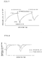
- FIG. 7 shows changes of a pressure loss of DPF by an operation time in a case where the trapping/collecting of the particulates and regeneration are repeatedly carried out.
- the slits were not formed
- the honeycomb structure having the diameter of 144 mm, length of 152 mm, partition wall thickness of 0.3 mm, and cell density of 46/cm 2 was used to plug one end of each through channel by the plugging portion as shown in FIG. 6 (a) or (b)
- a DPF according to the present invention was prepared in which one end of each through channel was plugged.
- the slits were formed in the vicinity of the plugging portions of the partition walls surrounding the respective through channels as shown in FIG. 1.
- each of these two DPFs was mounted in the exhaust system of the common rail type direct-injection diesel engine to trap/collect the particulates, and the changes of the trapping/collecting efficiency with the elapse of the operation time were checked. It is to be noted that a part of the exhaust gas is sucked and passes through filter paper in upstream and downstream of the DPF, a soot mass in the exhaust gas attached onto the filter paper is measured, and the trapping/collecting efficiency is obtained from the following equation.
- Trapping/collecting efficiency (%) ⁇ 1-(soot mass in DPF downstream)/(soot mass in DPF upstream) ⁇ ⁇ 100
- the honeycomb structure having the diameter of 144 mm, length of 152 mm, partition wall thickness of 0.43 mm, and cell density of 16/cm 2 was used to prepare the DPF in which one end of each through channel was plugged by the plugging portion and one slit having a length of 10 mm and various widths of 0 mm (without any through-slit) to 1.2 mm was formed per through channel in the vicinity of the plugging portion of the partition wall surrounding each through channel.
- Each of the DPFs was mounted in the exhaust system of the common rail type direct-injection diesel engine in the same manner as described above, and the particulates were trapped/collected to check a relation between the width of the slit and the trapping/collecting efficiency in the given operation time.
- the width of the slit is less than 0.2 mm, the ashes are not discharged well in some case. Therefore, the width is preferably set to 0.2 mm or more. However, when the width of the slit is less than 0.4 mm, the discharge of the ashes sometimes becomes incomplete in a low-speed operation at 1000 rpm or less. On the other hand, when the width of the slit is 0.4 mm or more, the ashes are substantially completely discharged even at the idling run time, and therefore this width is more preferable.
- the width of the slit is preferably in a range of 0.2 to 1 mm, and more preferably in a range of 0.4 to 0.8 mm.
- DPF the slits were not formed
- the conventional structure in which the honeycomb structure having the diameter of 144 mm, length of 152 mm, partition wall thickness of 0.38 mm, and cell density of 23/cm 2 was used to plug one end of each through channel by the plugging portion as shown in FIG. 6 (a) or (b)
- DPFs four types including the widths of slits of 0.2 mm, 0.4 mm, 0.8 mm, 1.0 mm
- the slits were formed in the vicinity of the plugging portions of the partition walls surrounding the respective through channels as shown in FIG. 1.
- each of these two DPFs was mounted in the exhaust system of the common rail type direct-injection diesel engine to repeatedly carry out the trapping/collecting of the particulates and the regeneration, and the changes of the pressure loss in a long-time use. It is to be noted that for the trapping/collecting and the regenerating, 7.5 g of particulates are trapped/collected and the regenerating is carried out in one cycle. This was carried out for 500 cycles.
- the pressure loss gradually rose, and a pressure loss of 1.3 times that at a test start time was indicated after 500 cycles. After the test ended, the deposition of the ashes which were non-burnt components in the particulates was recognized inside the DPF.
- the DPF according to the present invention in which the slits were formed in the vicinity of the plugging portions of the partition walls surrounding the respective through channels, with any of the widths of slits of 0.2 mm, 0.4 mm, 0.8 mm, and 1.0 mm, after 500 cycles, the same pressure loss and trapping/collecting efficiency as those at the test start time were obtained. After the test ended, there was not any deposition of the non-burnt components in the particulates inside the DPF.
- the honeycomb structure of the present invention when used as the filter for trapping/collecting the particulates included in the exhaust gas of the internal combustion engine such as the diesel engine, it is possible to remove the ashes deposited inside without requiring any special mechanism or apparatus as in the related art or without detaching the filter from the exhaust system. According to the manufacturing method of the present invention, the above-described honeycomb structure can easily and economically be prepared. Furthermore, in the exhaust gas purification system of the present invention, since the honeycomb structure is used as the filter, the ashes deposited inside the filter can easily be removed.
Applications Claiming Priority (2)
| Application Number | Priority Date | Filing Date | Title |
|---|---|---|---|
| JP2002297711 | 2002-10-10 | ||
| JP2002297711A JP4222599B2 (ja) | 2002-10-10 | 2002-10-10 | ハニカム構造体及びその製造方法並びに当該ハニカム構造体を用いた排ガス浄化システム |
Publications (2)
| Publication Number | Publication Date |
|---|---|
| EP1408207A1 true EP1408207A1 (de) | 2004-04-14 |
| EP1408207B1 EP1408207B1 (de) | 2006-05-31 |
Family
ID=32025572
Family Applications (1)
| Application Number | Title | Priority Date | Filing Date |
|---|---|---|---|
| EP03256389A Expired - Fee Related EP1408207B1 (de) | 2002-10-10 | 2003-10-09 | Wabenkörperstruktur mit Filtereigenshaften, dessen Herstellung und Verwendung in der Abgasreinigung |
Country Status (4)
| Country | Link |
|---|---|
| US (1) | US7645427B2 (de) |
| EP (1) | EP1408207B1 (de) |
| JP (1) | JP4222599B2 (de) |
| DE (1) | DE60305598T2 (de) |
Cited By (5)
| Publication number | Priority date | Publication date | Assignee | Title |
|---|---|---|---|---|
| WO2006040474A1 (fr) | 2004-10-14 | 2006-04-20 | Saint-Gobain Centre De Recherches Et D'etudes Europeen | Structure de filtration des gaz d'echappement d'un moteur a combustion interne et ligne d'echappement associee |
| US7825802B2 (en) | 2005-03-07 | 2010-11-02 | Schweizerische Bundesbahnen Sbb | Identification system and method of determining motion information |
| EP2505252A1 (de) * | 2011-03-30 | 2012-10-03 | NGK Insulators, Ltd. | Wabenstruktur und wabenförmiger katalytischer Körper |
| US11389769B2 (en) | 2015-10-30 | 2022-07-19 | Corning Incorported | Porous ceramic filters and methods for making the same |
| US11458464B2 (en) | 2017-10-31 | 2022-10-04 | Corning Incorporated | Honeycomb body and particulate filter comprising a honeycomb |
Families Citing this family (11)
| Publication number | Priority date | Publication date | Assignee | Title |
|---|---|---|---|---|
| JP4527963B2 (ja) * | 2003-11-04 | 2010-08-18 | 日本碍子株式会社 | マイクロ波乾燥法 |
| WO2005045207A1 (ja) * | 2003-11-06 | 2005-05-19 | Hitachi Metals, Ltd. | セラミックハニカムフィルタ、排気ガス浄化装置及び排気ガス浄化方法 |
| JP5142003B2 (ja) * | 2004-12-16 | 2013-02-13 | 日立金属株式会社 | ハニカム構造体 |
| WO2007063608A1 (ja) * | 2005-11-30 | 2007-06-07 | Ibiden Co., Ltd. | フィルタ、内燃機関の排気ガス浄化装置および排気ガス浄化方法 |
| JP5219740B2 (ja) * | 2008-10-31 | 2013-06-26 | 日本碍子株式会社 | ハニカム構造体、及びハニカム触媒体 |
| JP5219742B2 (ja) * | 2008-10-31 | 2013-06-26 | 日本碍子株式会社 | ハニカム構造体及びハニカム触媒体 |
| US8815183B2 (en) | 2009-08-31 | 2014-08-26 | Corning Incorporated | Zoned monolithic reactor and associated methods |
| EP2506960B1 (de) * | 2009-11-30 | 2014-01-22 | Corning Incorporated | Wabenkörpervorrichtungen mit schlitzförmigen interzellularen öffnungen |
| JP5814733B2 (ja) * | 2011-10-11 | 2015-11-17 | 株式会社アールデック | 脱臭カートリッジ |
| JP2012152750A (ja) * | 2012-04-17 | 2012-08-16 | Hitachi Metals Ltd | ハニカム構造体 |
| US9683474B2 (en) * | 2013-08-30 | 2017-06-20 | Dürr Systems Inc. | Block channel geometries and arrangements of thermal oxidizers |
Citations (5)
| Publication number | Priority date | Publication date | Assignee | Title |
|---|---|---|---|---|
| DE3744020A1 (de) * | 1987-12-24 | 1989-07-06 | Sotralentz Sa | Vorrichtung fuer die katalytische behandlung der verbrennungsabgase eines kraftfahrzeugmotors und verfahren zur herstellung einer katalysatorpatrone fuer eine solche vorrichtung |
| US5566545A (en) * | 1993-08-10 | 1996-10-22 | Ngk Insulators, Ltd. | Process and an apparatus for treating an exhaust gas, and a honeycomb structural exhaust gas filter |
| DE19835246A1 (de) * | 1998-08-04 | 2000-02-17 | Siemens Ag | Verfahren zur Herstellung eines Katalysatorkörpers |
| EP1132587A2 (de) * | 2000-03-09 | 2001-09-12 | Fleetguard, Inc. | Kombinierter katalytischer Umwandler und Filter |
| US20020050475A1 (en) * | 1999-05-28 | 2002-05-02 | Wolfgang Maus | Particle filter of metal foil and process for producing a particle filter |
Family Cites Families (15)
| Publication number | Priority date | Publication date | Assignee | Title |
|---|---|---|---|---|
| JPS5742316A (en) * | 1980-08-28 | 1982-03-09 | Ngk Insulators Ltd | Ceramic honeycomb filter |
| US4464185A (en) * | 1981-03-07 | 1984-08-07 | Nippon Soken, Inc. | Exhaust gas filter |
| JPS59199586A (ja) | 1983-04-26 | 1984-11-12 | 日本碍子株式会社 | セラミツクハニカム構造体 |
| JPS60112618A (ja) | 1983-11-21 | 1985-06-19 | Otsuka Chem Co Ltd | 変成されたチタン酸化合物の製造方法 |
| JPS6275803A (ja) | 1985-09-30 | 1987-04-07 | Mitsubishi Heavy Ind Ltd | 適応制御装置 |
| WO1993021429A1 (de) * | 1992-04-15 | 1993-10-28 | Fleck Carl M | Keramischer wabenkörper |
| EP0590814B1 (de) * | 1992-09-28 | 1996-12-18 | Ford Motor Company Limited | Vorrichtung zur Steuerung der Partikel- und der Abgasemission |
| JPH07256622A (ja) | 1994-02-04 | 1995-10-09 | Nippondenso Co Ltd | 未乾燥粘土質物の切断装置及び切断方法 |
| JPH0812460A (ja) | 1994-06-22 | 1996-01-16 | Osamu Yamamoto | ハニカム状セラミック構造体 |
| JPH0828247A (ja) | 1994-07-14 | 1996-01-30 | Ibiden Co Ltd | アッシュ除去機構付き排気ガス浄化装置 |
| JP3355943B2 (ja) * | 1996-07-18 | 2002-12-09 | 松下電器産業株式会社 | 排ガス浄化方法及び排ガスフィルタ並びにこれを用いた排ガスフィルタ浄化装置 |
| US6013599A (en) * | 1998-07-15 | 2000-01-11 | Redem Corporation | Self-regenerating diesel exhaust particulate filter and material |
| JP4398014B2 (ja) | 1999-08-06 | 2010-01-13 | イビデン株式会社 | 排気ガス浄化装置用フィルタの残存物除去方法及びその除去装置 |
| JP4298116B2 (ja) * | 2000-02-23 | 2009-07-15 | 日本碍子株式会社 | スリット付きハニカム構造体の製造方法及び製造装置 |
| JP4373067B2 (ja) * | 2002-10-10 | 2009-11-25 | 日本碍子株式会社 | ハニカム構造体及びその製造方法並びに当該ハニカム構造体を用いた排ガス浄化システム |
-
2002
- 2002-10-10 JP JP2002297711A patent/JP4222599B2/ja not_active Expired - Fee Related
-
2003
- 2003-09-23 US US10/667,339 patent/US7645427B2/en active Active
- 2003-10-09 EP EP03256389A patent/EP1408207B1/de not_active Expired - Fee Related
- 2003-10-09 DE DE60305598T patent/DE60305598T2/de not_active Expired - Lifetime
Patent Citations (5)
| Publication number | Priority date | Publication date | Assignee | Title |
|---|---|---|---|---|
| DE3744020A1 (de) * | 1987-12-24 | 1989-07-06 | Sotralentz Sa | Vorrichtung fuer die katalytische behandlung der verbrennungsabgase eines kraftfahrzeugmotors und verfahren zur herstellung einer katalysatorpatrone fuer eine solche vorrichtung |
| US5566545A (en) * | 1993-08-10 | 1996-10-22 | Ngk Insulators, Ltd. | Process and an apparatus for treating an exhaust gas, and a honeycomb structural exhaust gas filter |
| DE19835246A1 (de) * | 1998-08-04 | 2000-02-17 | Siemens Ag | Verfahren zur Herstellung eines Katalysatorkörpers |
| US20020050475A1 (en) * | 1999-05-28 | 2002-05-02 | Wolfgang Maus | Particle filter of metal foil and process for producing a particle filter |
| EP1132587A2 (de) * | 2000-03-09 | 2001-09-12 | Fleetguard, Inc. | Kombinierter katalytischer Umwandler und Filter |
Cited By (8)
| Publication number | Priority date | Publication date | Assignee | Title |
|---|---|---|---|---|
| WO2006040474A1 (fr) | 2004-10-14 | 2006-04-20 | Saint-Gobain Centre De Recherches Et D'etudes Europeen | Structure de filtration des gaz d'echappement d'un moteur a combustion interne et ligne d'echappement associee |
| FR2876731A1 (fr) | 2004-10-14 | 2006-04-21 | Saint Gobain Ct Recherches | Structure de filtration des gaz d'echappement d'un moteur a combustion interne et ligne d'echappement associee |
| US7825802B2 (en) | 2005-03-07 | 2010-11-02 | Schweizerische Bundesbahnen Sbb | Identification system and method of determining motion information |
| EP2505252A1 (de) * | 2011-03-30 | 2012-10-03 | NGK Insulators, Ltd. | Wabenstruktur und wabenförmiger katalytischer Körper |
| US11389769B2 (en) | 2015-10-30 | 2022-07-19 | Corning Incorported | Porous ceramic filters and methods for making the same |
| US11752469B2 (en) | 2015-10-30 | 2023-09-12 | Corning Incorporated | Porous ceramic filters and methods for making the same |
| US11458464B2 (en) | 2017-10-31 | 2022-10-04 | Corning Incorporated | Honeycomb body and particulate filter comprising a honeycomb |
| US11504705B2 (en) | 2017-10-31 | 2022-11-22 | Corning Incorporated | Method of evaluating filtration performance of a plugged honeycomb body |
Also Published As
| Publication number | Publication date |
|---|---|
| EP1408207B1 (de) | 2006-05-31 |
| JP2004130231A (ja) | 2004-04-30 |
| DE60305598D1 (de) | 2006-07-06 |
| JP4222599B2 (ja) | 2009-02-12 |
| US20040071611A1 (en) | 2004-04-15 |
| DE60305598T2 (de) | 2007-05-16 |
| US7645427B2 (en) | 2010-01-12 |
Similar Documents
| Publication | Publication Date | Title |
|---|---|---|
| EP1408208B1 (de) | Wabenstruktur, Verfahren zur Herstellung einer Wabenstruktur, und Abgasreinigungssystem mit Wabenstruktur | |
| US7645427B2 (en) | Honeycomb structure, manufacturing method of the structure, and exhaust gas purification system using the structure | |
| US6464744B2 (en) | Diesel particulate filters | |
| JP5313159B2 (ja) | 部分ウォールフロー型フィルタおよびディーゼル排気装置および方法 | |
| EP1375849B1 (de) | Keramischer Wabenfilter | |
| EP1598534A2 (de) | Wabenfilter und Abgasreinigungssystem | |
| US7326271B2 (en) | Honeycomb filter and method of manufacturing the same | |
| US7128961B2 (en) | Honeycomb structure, method for manufacturing honeycomb structure, and exhaust gas purification system using honeycomb structure | |
| JPH0549805B2 (de) | ||
| JPH0550323B2 (de) | ||
| JP5813965B2 (ja) | ハニカム構造体及び排ガス浄化装置 | |
| CN106499478B (zh) | 废气处理装置、催化剂的升温方法、蜂窝结构体的再生方法以及灰烬除去方法 | |
| JP4285342B2 (ja) | 排ガス浄化フィルタの製造方法 | |
| JP2544659B2 (ja) | パティキュレ―トトラップ装置 | |
| JP2008115717A (ja) | 排ガス浄化装置 | |
| JPS637817A (ja) | 排ガスフイルタ | |
| JP6635757B2 (ja) | ハニカムフィルタ | |
| JP2004232530A (ja) | ディーゼルパーティキュレートフィルタ | |
| JP2001221032A (ja) | ディーゼルエンジン用黒煙除去装置 | |
| JPS62132524A (ja) | 排ガスフイルタ | |
| JP2010209744A (ja) | 排ガス浄化装置 | |
| JPH0647618U (ja) | 排気ガス浄化装置 | |
| JPH05321632A (ja) | 排気ガス浄化装置 | |
| JPS61205314A (ja) | 排ガスフイルタ |
Legal Events
| Date | Code | Title | Description |
|---|---|---|---|
| PUAI | Public reference made under article 153(3) epc to a published international application that has entered the european phase |
Free format text: ORIGINAL CODE: 0009012 |
|
| AK | Designated contracting states |
Kind code of ref document: A1 Designated state(s): AT BE BG CH CY CZ DE DK EE ES FI FR GB GR HU IE IT LI LU MC NL PT RO SE SI SK TR |
|
| AX | Request for extension of the european patent |
Extension state: AL LT LV MK |
|
| 17P | Request for examination filed |
Effective date: 20040825 |
|
| AKX | Designation fees paid |
Designated state(s): DE FR |
|
| 17Q | First examination report despatched |
Effective date: 20041124 |
|
| GRAP | Despatch of communication of intention to grant a patent |
Free format text: ORIGINAL CODE: EPIDOSNIGR1 |
|
| GRAS | Grant fee paid |
Free format text: ORIGINAL CODE: EPIDOSNIGR3 |
|
| GRAA | (expected) grant |
Free format text: ORIGINAL CODE: 0009210 |
|
| AK | Designated contracting states |
Kind code of ref document: B1 Designated state(s): DE FR |
|
| REF | Corresponds to: |
Ref document number: 60305598 Country of ref document: DE Date of ref document: 20060706 Kind code of ref document: P |
|
| ET | Fr: translation filed | ||
| PLBE | No opposition filed within time limit |
Free format text: ORIGINAL CODE: 0009261 |
|
| STAA | Information on the status of an ep patent application or granted ep patent |
Free format text: STATUS: NO OPPOSITION FILED WITHIN TIME LIMIT |
|
| 26N | No opposition filed |
Effective date: 20070301 |
|
| PGFP | Annual fee paid to national office [announced via postgrant information from national office to epo] |
Ref country code: FR Payment date: 20091020 Year of fee payment: 7 |
|
| PG25 | Lapsed in a contracting state [announced via postgrant information from national office to epo] |
Ref country code: FR Free format text: LAPSE BECAUSE OF NON-PAYMENT OF DUE FEES Effective date: 20101102 |
|
| REG | Reference to a national code |
Ref country code: FR Ref legal event code: ST Effective date: 20110630 |
|
| PGFP | Annual fee paid to national office [announced via postgrant information from national office to epo] |
Ref country code: DE Payment date: 20210831 Year of fee payment: 19 |
|
| REG | Reference to a national code |
Ref country code: DE Ref legal event code: R119 Ref document number: 60305598 Country of ref document: DE |
|
| PG25 | Lapsed in a contracting state [announced via postgrant information from national office to epo] |
Ref country code: DE Free format text: LAPSE BECAUSE OF NON-PAYMENT OF DUE FEES Effective date: 20230503 |