EP1407664A1 - Anbauvorrichtung für das Spritzgestänge einer Feldspritze - Google Patents
Anbauvorrichtung für das Spritzgestänge einer Feldspritze Download PDFInfo
- Publication number
- EP1407664A1 EP1407664A1 EP03020913A EP03020913A EP1407664A1 EP 1407664 A1 EP1407664 A1 EP 1407664A1 EP 03020913 A EP03020913 A EP 03020913A EP 03020913 A EP03020913 A EP 03020913A EP 1407664 A1 EP1407664 A1 EP 1407664A1
- Authority
- EP
- European Patent Office
- Prior art keywords
- spray boom
- travel
- mounting device
- joint
- pendulum
- Prior art date
- Legal status (The legal status is an assumption and is not a legal conclusion. Google has not performed a legal analysis and makes no representation as to the accuracy of the status listed.)
- Granted
Links
Images




Classifications
-
- A—HUMAN NECESSITIES
- A01—AGRICULTURE; FORESTRY; ANIMAL HUSBANDRY; HUNTING; TRAPPING; FISHING
- A01M—CATCHING, TRAPPING OR SCARING OF ANIMALS; APPARATUS FOR THE DESTRUCTION OF NOXIOUS ANIMALS OR NOXIOUS PLANTS
- A01M7/00—Special adaptations or arrangements of liquid-spraying apparatus for purposes covered by this subclass
- A01M7/005—Special arrangements or adaptations of the spraying or distributing parts, e.g. adaptations or mounting of the spray booms, mounting of the nozzles, protection shields
- A01M7/0053—Mounting of the spraybooms
Definitions
- the invention relates to a mounting device for the Sprayer boom of a field sprayer according to the preamble of Claim 1.
- Such a hitch is for example in the German Patent 34 19 356 described.
- the Sprayer boom is in this field sprayer with kind of a
- the universal joint is suspended from the base frame, so that it is a in the direction of travel extending and lying axis arranged and about an upright axis pivoting movements can perform.
- the disadvantage of this known Attachment that of pitching and Velocity variations resulting vibrations and Forces are transferred to the spray boom, so that the Spray boom in and against the direction of travel to Swinging is excited.
- the invention is based on the object Attachment for a spray boom to create, which at least partially prevents pitching movements and / or Speed variations of the field sprayer on the Sprayer rods are transferred.
- the Spray boom by means of at least one other joint suspended in such a way that the base frame is opposite the spray boom in and against the direction of travel in Art can move a pushing movement.
- This will be the goal of Achieved invention, a uniform forward movement of the Sprayer linkage or a more uniform forward movement reach the spray boom.
- the Nonuniformity of the basic frame in his Forward movement especially on uneven and undulating Floor surfaces of the spray boom at least partially kept away. It will be at least through the according to the invention at least the suspensions Acceleration tips, shock and nonuniformity peaks kept away from the spray boom.
- the Spray boom by means of at least one example as Pendulum rod formed pendulum element via joints on Base frame is arranged, the joint axes lying and transverse to the direction of travel.
- this pendulum rod results in a simple and robust suspension of the Spray boom.
- the upper joint has two intersecting ones Has joint axes, one of which in the direction of travel and the other runs crosswise to the direction of travel and in each case in run at least approximately horizontal plane.
- a particularly good behavior of the sprayer boom is achieved by the pendulum rod at a distance above the center of gravity of the spray boom is arranged.
- a particularly simple embodiment of the joint member leaves can be achieved in that the joint member as a spring element trained and clamped at its top and bottom is. These configurations are not separate bearings required for joints.
- the movement of the sprayer boom too the frame is formed by the spring element as a Allows joint member in a simple manner.
- An advantageous Design of the spring element results from the fact that the spring element is designed as a plate-shaped element. In this case, the spring element is in such an advantageous manner arranged that the plane of the spring element is in extending upright and transverse to the direction of travel.
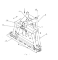
- the hitch 1 for the Spitzgest brieflye 2 a Field sprayer has the associated with the field sprayer Base frame 3 on. On the base frame 3 is about various Articulated links suspended the spray boom 2.
- the middle part 4 of the spray boom 2 is by means of two trained as pendulum rods 5 and 6 Pendulum elements attached to the base frame 3.
- each Pendulum rod 5,6 has a lower joint 7, whose Joint axis 8 transverse to the direction of travel 9 and horizontal runs on, with which the pendulum rods 5 hinged to the Middle part 4 of the linkage 2 are arranged.
- each Pendulum 5,6 is in each case by means of these joints 7 on the upper part of the central part 4 of the spray boom 2 articulated arranged.
- Each pendulum rod is 5.6 by means of another Joint 10, which is designed as a ball head bearing over a hinge pin 11 and 12 with the base frame. 3 connected.
- the hinge axis of this hinge pin 11 and 12th runs horizontally and in the direction of travel 9. Due to the Kugelkopf resonance can the pendulum rods 5 and 6 to the transverse to the direction of travel 9 and horizontal pendulum axis 14 swing.
- the spray boom 2 due to the articulated suspension of the pendulum rods 5,6 through the lower Joints 7 and by the possibility of movement, the Ball head is in and against the direction of travel 9 move, so that the spray boom 2 and the base frame. 3 towards the spray boom 2 in and against the Driving direction 9 can move in a kind of pushing movement.
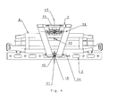
- the entire spray boom 2 to the in Travel direction 9 extending pivot axis 13 commute.
- the front upper suspension of the hinge pin 10 so arranged that the hinge pin is transverse to the direction of travel 9, as indicated by the double arrow 15 can move.
- the spray boom 2 can by means of the suspension in the pendulum members 5,6 against the Move base frame 3.
- the suspension of the sprayer boom 2 is such that the base frame 2 is opposite to the Spray boom 2 in and against the direction of travel 9 in a Move type pushing movement.
- the spray boom 2 is by means of the two as pendulum rods 5.6 trained pendulum elements via joints 7, on Base frame 10,11 arranged, the hinge axes 14 lying and transverse to the direction of travel 9.
- the pendulum rods 5, 6 are at a distance above the Center of gravity of the spray boom 2 is arranged.
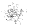
- the hitch device according to FIGS. 5 to 7 differs from the embodiment according to FIGS. 1 to 4, that the pendulum rods 5 and 6 of the joint members 17 and 18th is not arranged by means of joints, but as Spring element formed and at its top and bottom is clamped.
- the hinge members 17 and 18 are over the Clamping elements 19 with the base frame 3 and on the Clamping elements 20 with the middle part 4 of the spray boom 2 connected.
- the spring elements 17 are plate-shaped Elements formed.
- the plane of the spring elements 17th extend in an upright and crosswise direction Direction of travel 9.
- the mode of action of the spring element trained joint members 17 and 18 corresponds to the Operation according to the joint member 5 and 6 of FIG. 1 to 4.
- the spray boom 2 is opposite to the Can move base frame.
- the suspension of the sprayer boom 2 is such that the base frame 3 opposite to the Spray boom 2 in and against the direction of travel 9 in one Move type pushing movement. Due to the suspension of the Spray boom 2 by means of the plate-shaped spring elements 17, 18 on the base frame 3 affect both pitching movements non-uniform forward movement and shocks i n low Dimensions on the spray boom 2 off. The non-uniform Forward motion components are muted or completely off Spray boom 2 kept away.
Landscapes
- Life Sciences & Earth Sciences (AREA)
- Engineering & Computer Science (AREA)
- Insects & Arthropods (AREA)
- Pest Control & Pesticides (AREA)
- Wood Science & Technology (AREA)
- Zoology (AREA)
- Environmental Sciences (AREA)
- Catching Or Destruction (AREA)
- Special Spraying Apparatus (AREA)
Abstract
Description
- Fig. 1
- die Anbauvorrichtung in perspektivischer Darstellung,
- Fig. 2
- die Anbauvorrichtung des Spritzgestänges in der Ansicht von hinten,
- Fig. 3
- die Anbauvorrichtung in Seitenansicht,
- Fig. 4
- die Anbauvorrichtung in der Draufsicht,
- Fig. 5
- eine weitere Anbauvorrichtung in perspektivischer Darstellung,
- Fig. 6
- die Anbauvorrichtung nach Fig. 5 des Spritzgestänges in der Ansicht von hinten und
- Fig. 7
- die Anbauvorrichtung in Seitenansicht.
Claims (9)
- Anbauvorrichtung für das Spritzgestänge (2) einer Feldspritze, welche einen mit der Feldspritze verbundenen Grundrahmen (3) aufweist, an dem das Spritzgestänge (3) über Gelenkglieder (10,11) derart aufgehängt ist, dass es sowohl um eine in Fahrtrichtung (9) verlaufende und liegend angeordnete Achse (13) als auch um eine aufrechtstehende Achse (16) Schwenkbewegung ausführen kann, dadurch, gekennzeichnet, dass das Spritzgestänge (2) mittels zumindest eines weiteren Gelenkgliedes (5,6,17,18) derart aufgehängt ist, dass der Grundrahmen (3) sich gegenüber des Spritzgestänges (2) in und entgegen der Fahrtrichtung (9) in Art eine Schubbewegung bewegen kann.
- Anbauvorrichtung nach Anspruch 1, dadurch gekennzeichnet, dass das Spritzgestänge (2) mittels zumindest eines beispielsweise als Pendelstange (5,6) ausgebildeten Pendelelementes über Gelenke (7,10,11) am Grundrahmen (3) angeordnet ist, deren Gelenkachsen (8,14) liegend und quer zur Fahrtrichtung (9) verlaufen.
- Anbauvorrichtung nach Anspruch 2, dadurch gekennzeichnet, dass das obere Gelenk (10,11) der Pendelelementes (5,6) als Kugelkopflager ausgebildet ist.
- Anbauvorrichtung nach Anspruch 2, dadurch gekennzeichnet, dass das obere Gelenk des Pendelelementes als Kreuzgelenk ausgebildet ist.
- Anbauvorrichtung nach einem oder mehreren der vorstehenden Ansprüche, dadurch gekennzeichnet, dass das obere Gelenk (10,11) zwei sich kreuzende Gelenkachsen (14,16) aufweist, wovon die eine in Fahrtrichtung und die andere quer zur Fahrtrichtung (9) verläuft und jeweils in zumindest annähernd horizontaler Ebene verlaufen.
- Anbauvorrichtung nach einem oder mehreren der vorstehenden Ansprüche, dadurch gekennzeichnet, dass die Pendelstange (5,6) mit Abstand oberhalb des Schwerpunktes des Spritzgestänges (2) angeordnet ist.
- Anbauvorrichtung nach einem oder mehreren der vorstehenden Ansprüche, dadurch gekennzeichnet, dass das Gelenkglied (17,18) als Federelement ausgebildet und an seiner Ober- und Unterseite eingespannt ist.
- Anbauvorrichtung nach Anspruch 7, dadurch gekennzeichnet, dass das Federelement (17) als plattenförmiges Element ausgebildet ist.
- Anbauvorrichtung nach Anspruch 7 und/oder 8, dadurch gekennzeichnet, dass das die Ebene des Federelementes 17) sich in aufrechter Ebene und quer zur Fahrtrichtung (9) erstreckt.
Applications Claiming Priority (2)
| Application Number | Priority Date | Filing Date | Title |
|---|---|---|---|
| DE10245375 | 2002-09-28 | ||
| DE10245375 | 2002-09-28 |
Publications (2)
| Publication Number | Publication Date |
|---|---|
| EP1407664A1 true EP1407664A1 (de) | 2004-04-14 |
| EP1407664B1 EP1407664B1 (de) | 2007-01-24 |
Family
ID=32009961
Family Applications (1)
| Application Number | Title | Priority Date | Filing Date |
|---|---|---|---|
| EP03020913A Expired - Lifetime EP1407664B1 (de) | 2002-09-28 | 2003-09-16 | Anbauvorrichtung für das Spritzgestänge einer Feldspritze |
Country Status (4)
| Country | Link |
|---|---|
| EP (1) | EP1407664B1 (de) |
| AT (1) | ATE352199T1 (de) |
| DE (1) | DE50306359D1 (de) |
| DK (1) | DK1407664T3 (de) |
Cited By (3)
| Publication number | Priority date | Publication date | Assignee | Title |
|---|---|---|---|---|
| EP1525795A1 (de) * | 2003-10-23 | 2005-04-27 | Amazonen-Werke H. Dreyer GmbH & Co. KG | Landwirtschaftliche Verteilmaschine |
| WO2012027810A1 (pt) * | 2010-09-01 | 2012-03-08 | Stara S/A Indústria De Implementos Agrícolas | Aperfeiçoamento em barra central para pulverização e/ou distribuição de produtos |
| DE102007025751B4 (de) | 2007-06-01 | 2022-08-25 | Amazonen-Werke H. Dreyer SE & Co. KG | Verteilmaschine |
Families Citing this family (1)
| Publication number | Priority date | Publication date | Assignee | Title |
|---|---|---|---|---|
| FR3119731B1 (fr) * | 2021-02-18 | 2024-05-10 | Exel Ind | Ensemble pour rampe de pulverisation comprenant un dispositif anti-fouettement |
Citations (5)
| Publication number | Priority date | Publication date | Assignee | Title |
|---|---|---|---|---|
| DE2934020A1 (de) * | 1978-08-22 | 1980-03-06 | British Res Agricult Eng | Verteilerbalkenanordnung |
| DE3419356C1 (de) * | 1984-05-24 | 1985-05-30 | Amazonen-Werke H. Dreyer Gmbh & Co Kg, 4507 Hasbergen | Anbauvorrichtung fuer das Spritzgestaenge einer Feldspritze |
| EP0223170A1 (de) * | 1985-11-13 | 1987-05-27 | Amazonen-Werke H. Dreyer GmbH & Co. KG | Verteilmaschine, insbesondere Pneumatikdüngerstreuer |
| FR2671262A1 (fr) * | 1991-01-04 | 1992-07-10 | Tecnoma | Appareillage de traitement du sol ou de la vegetation, comprenant une rampe pouvant pivoter par rapport a des axes longitudinal et vertical. |
| FR2816805A1 (fr) * | 2000-11-21 | 2002-05-24 | Exel Ind | Rampe de pulverisation avec suspension amortie |
-
2003
- 2003-09-16 AT AT03020913T patent/ATE352199T1/de not_active IP Right Cessation
- 2003-09-16 DK DK03020913T patent/DK1407664T3/da active
- 2003-09-16 DE DE50306359T patent/DE50306359D1/de not_active Expired - Lifetime
- 2003-09-16 EP EP03020913A patent/EP1407664B1/de not_active Expired - Lifetime
Patent Citations (5)
| Publication number | Priority date | Publication date | Assignee | Title |
|---|---|---|---|---|
| DE2934020A1 (de) * | 1978-08-22 | 1980-03-06 | British Res Agricult Eng | Verteilerbalkenanordnung |
| DE3419356C1 (de) * | 1984-05-24 | 1985-05-30 | Amazonen-Werke H. Dreyer Gmbh & Co Kg, 4507 Hasbergen | Anbauvorrichtung fuer das Spritzgestaenge einer Feldspritze |
| EP0223170A1 (de) * | 1985-11-13 | 1987-05-27 | Amazonen-Werke H. Dreyer GmbH & Co. KG | Verteilmaschine, insbesondere Pneumatikdüngerstreuer |
| FR2671262A1 (fr) * | 1991-01-04 | 1992-07-10 | Tecnoma | Appareillage de traitement du sol ou de la vegetation, comprenant une rampe pouvant pivoter par rapport a des axes longitudinal et vertical. |
| FR2816805A1 (fr) * | 2000-11-21 | 2002-05-24 | Exel Ind | Rampe de pulverisation avec suspension amortie |
Cited By (3)
| Publication number | Priority date | Publication date | Assignee | Title |
|---|---|---|---|---|
| EP1525795A1 (de) * | 2003-10-23 | 2005-04-27 | Amazonen-Werke H. Dreyer GmbH & Co. KG | Landwirtschaftliche Verteilmaschine |
| DE102007025751B4 (de) | 2007-06-01 | 2022-08-25 | Amazonen-Werke H. Dreyer SE & Co. KG | Verteilmaschine |
| WO2012027810A1 (pt) * | 2010-09-01 | 2012-03-08 | Stara S/A Indústria De Implementos Agrícolas | Aperfeiçoamento em barra central para pulverização e/ou distribuição de produtos |
Also Published As
| Publication number | Publication date |
|---|---|
| DK1407664T3 (da) | 2007-03-26 |
| DE50306359D1 (de) | 2007-03-15 |
| EP1407664B1 (de) | 2007-01-24 |
| ATE352199T1 (de) | 2007-02-15 |
Similar Documents
| Publication | Publication Date | Title |
|---|---|---|
| DE3826930C2 (de) | Radaufhängungssystem | |
| AT405166B (de) | Drehgestell-fahrwerk für ein schienenfahrzeug | |
| DE7922136U1 (de) | Elastische aufhaengung fuer die fahrerkabine eines fahrzeugs | |
| DE10224065B4 (de) | Kraftfahrzeug mit einer Fahrgastzelle und einem relativ zu dieser schwingbeweglichen Grundrahmen | |
| EP1407664B1 (de) | Anbauvorrichtung für das Spritzgestänge einer Feldspritze | |
| DE1782942C3 (de) | Einrichtung zum Befestigen eines landwirtschaftlichen Gerätes an der genormten Dreipunktkupplung eines Schleppers | |
| DE2640128A1 (de) | Pistenpflegefahrzeug | |
| DE3039051C2 (de) | Querführung für eine Starrachse | |
| DE2445629A1 (de) | An einem fahrzeug um eine horizontale achse eines gelenks schwenkbar angeordnete fahrerkabine | |
| DE4029288A1 (de) | Fahrzeug mit fahrwerk | |
| EP0754576B1 (de) | Aufhängung der lenkbaren Starrachse eines geländegängigen Fahrzeuges | |
| DE1222382B (de) | Strassengelenkwagenzug | |
| DE888049C (de) | Nachgiebige Verbindung einer Radaufhaengung oder eines Achsaggregates mit dem Rahmen oder Fahrzeugoberbau | |
| DE1505720A1 (de) | Aufhaengung eines Hilfsrahmens am Hautprahmen eines Fahrzeuges,insbesondere eines Kraftfahrzeuges | |
| DE3518903C2 (de) | ||
| AT501922B1 (de) | Nutzfahrzeug, insbesondere lastkraftwagen, mit spezieller aufhängung und lenkung zweier benachbarter vorderachsen | |
| DE10130636B4 (de) | Vorrichtung zur Querführung eines Achskörpers einer Fahrzeugachse, insbesondere eines Nutzfahrzeugs | |
| DE2160227A1 (de) | Hoehenverstellbare spritzgestaengeaufhaengung fuer fahrbare schaedlingsbekaempfungsgeraete in feldkulturen mit einem quer zur fahrtrichtung liegenden spritzgestaenge | |
| DE10323021B3 (de) | Warntafel für den Strassenverkehr mit einem Basisträger und einem Aufpralldämpfer gegen Auffahrunfälle | |
| DE2557250C3 (de) | Fahrgestell für Anhängerfahrzeuge, insbesondere Wohnwagen | |
| DE3740407C2 (de) | ||
| DE976736C (de) | Aufhaengung von Schwinghalbachsen an Kraftfahrzeugen | |
| DE3807301A1 (de) | Radfuehrungsanordnung | |
| DE2553960A1 (de) | Fahrzeugradaufhaengung | |
| DE1430001C (de) | Schwingachsenaufhängung für die angetriebenen Räder eines Kraftfahrzeugs |
Legal Events
| Date | Code | Title | Description |
|---|---|---|---|
| PUAI | Public reference made under article 153(3) epc to a published international application that has entered the european phase |
Free format text: ORIGINAL CODE: 0009012 |
|
| AK | Designated contracting states |
Kind code of ref document: A1 Designated state(s): AT BE BG CH CY CZ DE DK EE ES FI FR GB GR HU IE IT LI LU MC NL PT RO SE SI SK TR |
|
| AX | Request for extension of the european patent |
Extension state: AL LT LV MK |
|
| 17P | Request for examination filed |
Effective date: 20040504 |
|
| AKX | Designation fees paid |
Designated state(s): AT BE BG CH CY CZ DE DK EE ES FI FR GB GR HU IE IT LI LU MC NL PT RO SE SI SK TR |
|
| GRAP | Despatch of communication of intention to grant a patent |
Free format text: ORIGINAL CODE: EPIDOSNIGR1 |
|
| GRAS | Grant fee paid |
Free format text: ORIGINAL CODE: EPIDOSNIGR3 |
|
| GRAA | (expected) grant |
Free format text: ORIGINAL CODE: 0009210 |
|
| AK | Designated contracting states |
Kind code of ref document: B1 Designated state(s): AT BE BG CH CY CZ DE DK EE ES FI FR GB GR HU IE IT LI LU MC NL PT RO SE SI SK TR |
|
| PG25 | Lapsed in a contracting state [announced via postgrant information from national office to epo] |
Ref country code: IE Free format text: LAPSE BECAUSE OF FAILURE TO SUBMIT A TRANSLATION OF THE DESCRIPTION OR TO PAY THE FEE WITHIN THE PRESCRIBED TIME-LIMIT Effective date: 20070124 Ref country code: FI Free format text: LAPSE BECAUSE OF FAILURE TO SUBMIT A TRANSLATION OF THE DESCRIPTION OR TO PAY THE FEE WITHIN THE PRESCRIBED TIME-LIMIT Effective date: 20070124 Ref country code: SI Free format text: LAPSE BECAUSE OF FAILURE TO SUBMIT A TRANSLATION OF THE DESCRIPTION OR TO PAY THE FEE WITHIN THE PRESCRIBED TIME-LIMIT Effective date: 20070124 |
|
| REG | Reference to a national code |
Ref country code: GB Ref legal event code: FG4D Free format text: NOT ENGLISH |
|
| GBT | Gb: translation of ep patent filed (gb section 77(6)(a)/1977) |
Effective date: 20070124 |
|
| REG | Reference to a national code |
Ref country code: CH Ref legal event code: EP |
|
| REG | Reference to a national code |
Ref country code: IE Ref legal event code: FG4D Free format text: LANGUAGE OF EP DOCUMENT: GERMAN |
|
| REF | Corresponds to: |
Ref document number: 50306359 Country of ref document: DE Date of ref document: 20070315 Kind code of ref document: P |
|
| REG | Reference to a national code |
Ref country code: DK Ref legal event code: T3 |
|
| PG25 | Lapsed in a contracting state [announced via postgrant information from national office to epo] |
Ref country code: SE Free format text: LAPSE BECAUSE OF FAILURE TO SUBMIT A TRANSLATION OF THE DESCRIPTION OR TO PAY THE FEE WITHIN THE PRESCRIBED TIME-LIMIT Effective date: 20070424 |
|
| PG25 | Lapsed in a contracting state [announced via postgrant information from national office to epo] |
Ref country code: BG Free format text: LAPSE BECAUSE OF EXPIRATION OF PROTECTION Effective date: 20070425 |
|
| PG25 | Lapsed in a contracting state [announced via postgrant information from national office to epo] |
Ref country code: ES Free format text: LAPSE BECAUSE OF FAILURE TO SUBMIT A TRANSLATION OF THE DESCRIPTION OR TO PAY THE FEE WITHIN THE PRESCRIBED TIME-LIMIT Effective date: 20070505 |
|
| PG25 | Lapsed in a contracting state [announced via postgrant information from national office to epo] |
Ref country code: PT Free format text: LAPSE BECAUSE OF FAILURE TO SUBMIT A TRANSLATION OF THE DESCRIPTION OR TO PAY THE FEE WITHIN THE PRESCRIBED TIME-LIMIT Effective date: 20070625 |
|
| ET | Fr: translation filed | ||
| REG | Reference to a national code |
Ref country code: IE Ref legal event code: FD4D |
|
| PG25 | Lapsed in a contracting state [announced via postgrant information from national office to epo] |
Ref country code: SK Free format text: LAPSE BECAUSE OF FAILURE TO SUBMIT A TRANSLATION OF THE DESCRIPTION OR TO PAY THE FEE WITHIN THE PRESCRIBED TIME-LIMIT Effective date: 20070124 |
|
| PLBE | No opposition filed within time limit |
Free format text: ORIGINAL CODE: 0009261 |
|
| STAA | Information on the status of an ep patent application or granted ep patent |
Free format text: STATUS: NO OPPOSITION FILED WITHIN TIME LIMIT |
|
| 26N | No opposition filed |
Effective date: 20071025 |
|
| PG25 | Lapsed in a contracting state [announced via postgrant information from national office to epo] |
Ref country code: RO Free format text: LAPSE BECAUSE OF FAILURE TO SUBMIT A TRANSLATION OF THE DESCRIPTION OR TO PAY THE FEE WITHIN THE PRESCRIBED TIME-LIMIT Effective date: 20070124 |
|
| BERE | Be: lapsed |
Owner name: AMAZONEN-WERKE H. DREYER G.M.B.H. & CO. KG Effective date: 20070930 |
|
| PG25 | Lapsed in a contracting state [announced via postgrant information from national office to epo] |
Ref country code: GR Free format text: LAPSE BECAUSE OF FAILURE TO SUBMIT A TRANSLATION OF THE DESCRIPTION OR TO PAY THE FEE WITHIN THE PRESCRIBED TIME-LIMIT Effective date: 20070425 Ref country code: MC Free format text: LAPSE BECAUSE OF NON-PAYMENT OF DUE FEES Effective date: 20070930 |
|
| REG | Reference to a national code |
Ref country code: CH Ref legal event code: PL |
|
| PG25 | Lapsed in a contracting state [announced via postgrant information from national office to epo] |
Ref country code: LI Free format text: LAPSE BECAUSE OF NON-PAYMENT OF DUE FEES Effective date: 20070930 Ref country code: CH Free format text: LAPSE BECAUSE OF NON-PAYMENT OF DUE FEES Effective date: 20070930 |
|
| PG25 | Lapsed in a contracting state [announced via postgrant information from national office to epo] |
Ref country code: BE Free format text: LAPSE BECAUSE OF NON-PAYMENT OF DUE FEES Effective date: 20070930 |
|
| PG25 | Lapsed in a contracting state [announced via postgrant information from national office to epo] |
Ref country code: AT Free format text: LAPSE BECAUSE OF NON-PAYMENT OF DUE FEES Effective date: 20070916 |
|
| PG25 | Lapsed in a contracting state [announced via postgrant information from national office to epo] |
Ref country code: EE Free format text: LAPSE BECAUSE OF FAILURE TO SUBMIT A TRANSLATION OF THE DESCRIPTION OR TO PAY THE FEE WITHIN THE PRESCRIBED TIME-LIMIT Effective date: 20070124 |
|
| PG25 | Lapsed in a contracting state [announced via postgrant information from national office to epo] |
Ref country code: CY Free format text: LAPSE BECAUSE OF FAILURE TO SUBMIT A TRANSLATION OF THE DESCRIPTION OR TO PAY THE FEE WITHIN THE PRESCRIBED TIME-LIMIT Effective date: 20070124 |
|
| PG25 | Lapsed in a contracting state [announced via postgrant information from national office to epo] |
Ref country code: LU Free format text: LAPSE BECAUSE OF NON-PAYMENT OF DUE FEES Effective date: 20070916 |
|
| PG25 | Lapsed in a contracting state [announced via postgrant information from national office to epo] |
Ref country code: TR Free format text: LAPSE BECAUSE OF FAILURE TO SUBMIT A TRANSLATION OF THE DESCRIPTION OR TO PAY THE FEE WITHIN THE PRESCRIBED TIME-LIMIT Effective date: 20070124 Ref country code: HU Free format text: LAPSE BECAUSE OF FAILURE TO SUBMIT A TRANSLATION OF THE DESCRIPTION OR TO PAY THE FEE WITHIN THE PRESCRIBED TIME-LIMIT Effective date: 20070725 |
|
| REG | Reference to a national code |
Ref country code: FR Ref legal event code: PLFP Year of fee payment: 14 |
|
| REG | Reference to a national code |
Ref country code: FR Ref legal event code: PLFP Year of fee payment: 15 |
|
| REG | Reference to a national code |
Ref country code: FR Ref legal event code: PLFP Year of fee payment: 16 |
|
| PGFP | Annual fee paid to national office [announced via postgrant information from national office to epo] |
Ref country code: GB Payment date: 20180627 Year of fee payment: 17 |
|
| PG25 | Lapsed in a contracting state [announced via postgrant information from national office to epo] |
Ref country code: IT Free format text: LAPSE BECAUSE OF NON-PAYMENT OF DUE FEES Effective date: 20190916 |
|
| GBPC | Gb: european patent ceased through non-payment of renewal fee |
Effective date: 20190916 |
|
| PG25 | Lapsed in a contracting state [announced via postgrant information from national office to epo] |
Ref country code: GB Free format text: LAPSE BECAUSE OF NON-PAYMENT OF DUE FEES Effective date: 20190916 |
|
| REG | Reference to a national code |
Ref country code: DE Ref legal event code: R081 Ref document number: 50306359 Country of ref document: DE Owner name: AMAZONEN-WERKE H. DREYER SE & CO. KG, DE Free format text: FORMER OWNER: AMAZONEN-WERKE H. DREYER GMBH & CO. KG, 49205 HASBERGEN, DE |
|
| PGFP | Annual fee paid to national office [announced via postgrant information from national office to epo] |
Ref country code: NL Payment date: 20220816 Year of fee payment: 20 |
|
| PGFP | Annual fee paid to national office [announced via postgrant information from national office to epo] |
Ref country code: DK Payment date: 20220909 Year of fee payment: 20 Ref country code: DE Payment date: 20220609 Year of fee payment: 20 Ref country code: CZ Payment date: 20220826 Year of fee payment: 20 |
|
| PGFP | Annual fee paid to national office [announced via postgrant information from national office to epo] |
Ref country code: FR Payment date: 20220709 Year of fee payment: 20 |
|
| P01 | Opt-out of the competence of the unified patent court (upc) registered |
Effective date: 20230523 |
|
| REG | Reference to a national code |
Ref country code: DE Ref legal event code: R071 Ref document number: 50306359 Country of ref document: DE |
|
| REG | Reference to a national code |
Ref country code: DK Ref legal event code: EUP Expiry date: 20230916 |
|
| REG | Reference to a national code |
Ref country code: NL Ref legal event code: MK Effective date: 20230915 |
|
| PG25 | Lapsed in a contracting state [announced via postgrant information from national office to epo] |
Ref country code: CZ Free format text: LAPSE BECAUSE OF EXPIRATION OF PROTECTION Effective date: 20230916 |