EP1405111B1 - Method of fabricating arrayed optical fibre collimators - Google Patents
Method of fabricating arrayed optical fibre collimators Download PDFInfo
- Publication number
- EP1405111B1 EP1405111B1 EP02739202A EP02739202A EP1405111B1 EP 1405111 B1 EP1405111 B1 EP 1405111B1 EP 02739202 A EP02739202 A EP 02739202A EP 02739202 A EP02739202 A EP 02739202A EP 1405111 B1 EP1405111 B1 EP 1405111B1
- Authority
- EP
- European Patent Office
- Prior art keywords
- optical fiber
- optical
- block
- substrate
- microlens
- Prior art date
- Legal status (The legal status is an assumption and is not a legal conclusion. Google has not performed a legal analysis and makes no representation as to the accuracy of the status listed.)
- Expired - Lifetime
Links
- 239000013307 optical fiber Substances 0.000 title claims abstract description 87
- 238000004519 manufacturing process Methods 0.000 title 1
- 239000000758 substrate Substances 0.000 claims abstract description 70
- 230000003287 optical effect Effects 0.000 claims abstract description 49
- 238000000034 method Methods 0.000 claims abstract description 32
- 239000000835 fiber Substances 0.000 claims description 13
- 230000008878 coupling Effects 0.000 description 11
- 238000010168 coupling process Methods 0.000 description 11
- 238000005859 coupling reaction Methods 0.000 description 11
- 239000000853 adhesive Substances 0.000 description 7
- 230000001070 adhesive effect Effects 0.000 description 7
- 230000000717 retained effect Effects 0.000 description 7
- 238000010586 diagram Methods 0.000 description 5
- 125000006850 spacer group Chemical group 0.000 description 5
- VYPSYNLAJGMNEJ-UHFFFAOYSA-N Silicium dioxide Chemical compound O=[Si]=O VYPSYNLAJGMNEJ-UHFFFAOYSA-N 0.000 description 2
- 230000005540 biological transmission Effects 0.000 description 2
- 230000007423 decrease Effects 0.000 description 2
- 238000012545 processing Methods 0.000 description 2
- 239000007787 solid Substances 0.000 description 2
- XUIMIQQOPSSXEZ-UHFFFAOYSA-N Silicon Chemical compound [Si] XUIMIQQOPSSXEZ-UHFFFAOYSA-N 0.000 description 1
- 238000003491 array Methods 0.000 description 1
- 239000011248 coating agent Substances 0.000 description 1
- 238000000576 coating method Methods 0.000 description 1
- 229910052681 coesite Inorganic materials 0.000 description 1
- 238000010276 construction Methods 0.000 description 1
- 229910052906 cristobalite Inorganic materials 0.000 description 1
- 230000001419 dependent effect Effects 0.000 description 1
- 238000001514 detection method Methods 0.000 description 1
- 239000011521 glass Substances 0.000 description 1
- 238000012994 industrial processing Methods 0.000 description 1
- 230000010354 integration Effects 0.000 description 1
- 238000012986 modification Methods 0.000 description 1
- 230000004048 modification Effects 0.000 description 1
- 229910052710 silicon Inorganic materials 0.000 description 1
- 239000010703 silicon Substances 0.000 description 1
- 239000000377 silicon dioxide Substances 0.000 description 1
- 229910052682 stishovite Inorganic materials 0.000 description 1
- 229910052905 tridymite Inorganic materials 0.000 description 1
- 230000000007 visual effect Effects 0.000 description 1
- 239000011800 void material Substances 0.000 description 1
Images


Classifications
-
- G—PHYSICS
- G02—OPTICS
- G02B—OPTICAL ELEMENTS, SYSTEMS OR APPARATUS
- G02B27/00—Optical systems or apparatus not provided for by any of the groups G02B1/00 - G02B26/00, G02B30/00
- G02B27/62—Optical apparatus specially adapted for adjusting optical elements during the assembly of optical systems
-
- G—PHYSICS
- G02—OPTICS
- G02B—OPTICAL ELEMENTS, SYSTEMS OR APPARATUS
- G02B6/00—Light guides; Structural details of arrangements comprising light guides and other optical elements, e.g. couplings
- G02B6/24—Coupling light guides
- G02B6/26—Optical coupling means
- G02B6/32—Optical coupling means having lens focusing means positioned between opposed fibre ends
-
- G—PHYSICS
- G02—OPTICS
- G02B—OPTICAL ELEMENTS, SYSTEMS OR APPARATUS
- G02B6/00—Light guides; Structural details of arrangements comprising light guides and other optical elements, e.g. couplings
- G02B6/24—Coupling light guides
- G02B6/42—Coupling light guides with opto-electronic elements
- G02B6/4201—Packages, e.g. shape, construction, internal or external details
- G02B6/4219—Mechanical fixtures for holding or positioning the elements relative to each other in the couplings; Alignment methods for the elements, e.g. measuring or observing methods especially used therefor
- G02B6/422—Active alignment, i.e. moving the elements in response to the detected degree of coupling or position of the elements
- G02B6/4225—Active alignment, i.e. moving the elements in response to the detected degree of coupling or position of the elements by a direct measurement of the degree of coupling, e.g. the amount of light power coupled to the fibre or the opto-electronic element
-
- G—PHYSICS
- G02—OPTICS
- G02B—OPTICAL ELEMENTS, SYSTEMS OR APPARATUS
- G02B6/00—Light guides; Structural details of arrangements comprising light guides and other optical elements, e.g. couplings
- G02B6/24—Coupling light guides
- G02B6/42—Coupling light guides with opto-electronic elements
- G02B6/4201—Packages, e.g. shape, construction, internal or external details
- G02B6/4249—Packages, e.g. shape, construction, internal or external details comprising arrays of active devices and fibres
-
- G—PHYSICS
- G02—OPTICS
- G02B—OPTICAL ELEMENTS, SYSTEMS OR APPARATUS
- G02B6/00—Light guides; Structural details of arrangements comprising light guides and other optical elements, e.g. couplings
- G02B6/24—Coupling light guides
- G02B6/42—Coupling light guides with opto-electronic elements
- G02B6/4201—Packages, e.g. shape, construction, internal or external details
- G02B6/4204—Packages, e.g. shape, construction, internal or external details the coupling comprising intermediate optical elements, e.g. lenses, holograms
-
- G—PHYSICS
- G02—OPTICS
- G02B—OPTICAL ELEMENTS, SYSTEMS OR APPARATUS
- G02B6/00—Light guides; Structural details of arrangements comprising light guides and other optical elements, e.g. couplings
- G02B6/24—Coupling light guides
- G02B6/42—Coupling light guides with opto-electronic elements
- G02B6/4201—Packages, e.g. shape, construction, internal or external details
- G02B6/4219—Mechanical fixtures for holding or positioning the elements relative to each other in the couplings; Alignment methods for the elements, e.g. measuring or observing methods especially used therefor
- G02B6/422—Active alignment, i.e. moving the elements in response to the detected degree of coupling or position of the elements
- G02B6/4226—Positioning means for moving the elements into alignment, e.g. alignment screws, deformation of the mount
Definitions
- the present invention is generally directed to arrayed optical fiber collimators and, more specifically, a system and method for fabricating arrayed optical fiber collimators.
- arrayed optical fiber collimators are increasingly utilized in optical systems.
- arrayed optical fiber collimators have been used or proposed for use in conjunction with various optical chips, e.g., optical isolator chips and optical circulator chips.
- optical chips e.g., optical isolator chips and optical circulator chips.
- DWDM dense wavelength division multiplexing
- the effectiveness of optical devices that use collimating arrays, incorporating graded-index (GRIN), aspheric or Fresnel microlenses are highly dependent on the configuration of a given optical fiber collimator array. As such, it is important to configure the fiber collimator array to reduce optical losses.
- GRIN graded-index
- aspheric or Fresnel microlenses are highly dependent on the configuration of a given optical fiber collimator array. As such,
- EP 0619 505 relates to an optical collimator comprising an optical fiber array for aligning and fixing optical fibers, and a microlens array arranged near the optical fiber array at a predetermined distance and a method of aligning optical axes of the optical collimator.
- US 5 815 626 relates to an optical transmission device, a solid state laser device, and a laser beam processing device having the optical transmission device or the solid state laser device for transmitting a laser beam with a high focusability used for laser beam processing for industrial processing purposes, medical laser application purpose, and the like.
- the present invention is directed to a method for actively aligning components of an arrayed optical fiber collimator according to the steps of claim 1.
- a first fixture is provided for receiving and retaining an optical fiber array block, which receives and retains a plurality of individual optical fibers.
- a second fixture is provided for receiving and retaining a microlens array substrate that includes a plurality of microlenses integrated along a microlens surface and a substrate surface opposite the microlens surface.
- a third fixture is provided for receiving and retaining at least a portion of a first light receiver that is positioned to receive a light beam from at least one of the integrated microlenses.
- At least one light beam is provided from the light source to at least one of the plurality of individual optical fibers.
- the relative position of at least one of the microlens array substrate and the optical fiber array block is then adjusted to maximize the optical power of the light beam received by the first light receiver.
- a finished arrayed optical fiber collimator is provided by fixing the optical fiber array block to the microlens array substrate when the optical power provided by the integrated microlens is at a maximum.
- Fig. 1 shows an arrayed optical device 100 that includes a first arrayed optical fiber collimator 102 and a second arrayed optical fiber collimator 112.
- the first arrayed optical fiber collimator 102 includes a first optical fiber array block 104, which retains a plurality of optical fibers 101, and a first microlens array substrate 106, which includes a plurality of microlenses integrated along a microlens surface.
- the second arrayed optical fiber collimator 112 includes a second optical fiber array block 114, which retains a second plurality of optical fibers 111, and a second microlens array substrate 116, which includes a plurality of microlenses integrated along a microlens surface.
- An optical chip (e.g., an isolator chip, a circulator chip, filter, etc.) 108 is retained within a groove 118 formed in substrate 120.
- Both the first arrayed optical fiber collimator 102 and the second arrayed optical fiber collimator 114 are coupled (e.g., with an adhesive) to the substrate 120 such that they are fixed in relation to each other and the chip 108 after alignment.
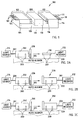
- a procedure for aligning an optical fiber array block 202, which retains a plurality of optical fibers 201 (e.g., eight optical fibers), with a microlens array substrate 206 is depicted.
- the fibers 201 are coupled to a light source 214 that preferably provides a light beam to each of the fibers 201.
- the light source 214 may only provide a light beam to fibers 201 at each end.
- a first fixture 203 receives and retains the block 202 and is coupled to an auto-aligner 220 to facilitate movement of the block 202 with respect to substrate 206 and a single mode collimated (SMC) optical fiber 210.
- SMC single mode collimated
- the substrate 206 is received and retained by a second fixture 205, which attaches the substrate 206 to the auto-aligner 220 facilitating movement of the substrate 206 by the auto-aligner 220.
- the SMC optical fiber 210 is coupled to a receiver 212 and is received and retained by a fixture 207.
- the block 202 and the substrate 206 are adjusted in relation to each other to achieve maximum optical power from each fiber 201 and its corresponding microlens, as seen by the receiver 212 (through the SMC optical fiber 210). It will be appreciated that to achieve optimal alignment between the plurality of optical fibers 201 of the block 202 and microlenses of the substrate 206 requires precise indexing by the auto-aligner 220.
- the block 202 is affixed (e.g., with an optical adhesive) to the substrate 206, which provides a finished arrayed optical fiber collimator 230 that is utilized in conjunction with the procedure of Fig. 2B.
- the plurality of optical fibers 201 of the collimator 230 are coupled to the receiver 212.
- the collimator 230 is then coupled to the auto-aligner 220 through a fixture 209 that receives and retains the collimator 230.
- a light source 214 is then coupled to a plurality of optical fibers 231 that are retained in optical fiber array block 232.
- the optical fiber array block 232 is then coupled to the auto-aligner 220 through the fixture 203.
- a microlens array substrate 236 is then coupled to the auto-aligner 220, through a fixture 205.
- the block 232 and the substrate 236 are then moved by the auto-aligner 220 to facilitate optimum optical power transfer through the optical fibers 231, retained in the block 232, and microlenses of the substrate 236, as detected by the receiver 212 through the collimator 230.
- the block 232 is fixed (e.g., with an optical adhesive) to the substrate 236 forming another collimator 250, as is shown in Fig. 2C.
- the collimator 250 is then coupled to the auto-aligner 220, utilizing the fixture 209, and is coupled to the light receiver 212 through the plurality of optical fibers 231.
- An optical fiber array block 262 which retains a plurality of optical fibers 261 that are coupled to the light source 214, is then coupled to the auto-aligner 220 through the fixture 203, which receives and retains the block 262.
- a substrate 266 is then coupled to the auto-aligner 220, through a fixture 205, which receives and retains the substrate 266. Similar to the procedure of Fig.
- the block 262 and the substrate 266 are aligned with each other to provide maximum power transfer through the microlenses of the substrate 266, as seen by the light receiver 212, through the collimator 250.
- a procedure has been described wherein one fabricated collimator is utilized to align a next microlens array substrate with a next optical fiber array block to produce a next collimator.
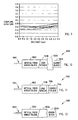
- Fig. 3 depicts a graph, which shows the coupling loss of a pair of fabricated collimators using the SMC fiber procedure and using the stepping procedure, described above.
- the minimum coupling loss of a pair of collimators aligned with the SMC fiber was about 1.5 dB when one collimator was placed five to six millimeters from the other collimator which was aligned in the same manner.
- a 0.6 dB decrease was achieved by utilizing a prior fabricated collimator to align a next fabricated collimator, when the fabricated collimator was placed five to six millimeters from the other collimator.
- misalignment can remain without a perfect master collimator and the first two or three collimators must typically be discarded.
- alignment through the detection of the collimated light beam is not particularly sensitive to X, Y and Z axis movement since the collimated light beam is generally to wide to align in micron or sub-micron order (beam diameter is typically in a range of 100 to 140 microns in this case).
- Fig. 4 depicts an alternative system for aligning an optical fiber array block 402 with a microlens array substrate 406.
- a light source e.g., a laser diode
- the circulator 416 is also coupled to a plurality of optical fibers 401 that are retained in the block 402.
- the block 402 is coupled to an auto-aligner 420 by a fixture 403, which receives and retains the block 402.
- the substrate 406 is coupled to the auto-aligner 420 by a fixture 405, which receives and retains the substrate 406.
- a half-mirror 422 is coupled to the auto-aligner 420 by a fixture 411, which receives and retains the mirror 422.
- a charge-coupled device (CCD) camera 424 is coupled to the auto-aligner 420 through a fixture 413 that receives and retains the CCD camera 424. In this manner, the auto-aligner 420 can adjust the block 402, the substrate 406 and the mirror 422 with respect to the camera 424 and in relation to each other in three dimensions (X, Y and Z).
- the block 402 and the mirror 422 are brought into contact by the auto-aligner 420, such that they can be aligned in the ⁇ X and ⁇ Y directions for maximum optical power transfer. This puts the block 402 and the mirror 422 in parallel.
- the mirror 422 is moved away from the block 402 in the Z direction.
- the substrate 406 is placed between the block 402 and the mirror 422.
- the light source 414 then provides a light beam to at least a first one of the optical fibers 401 and a last one of the optical fibers 401 such that visual alignment is conducted by visually examining the lighting position through the microlens of the substrate 406 with the camera 424.
- the mirror 422 and the substrate 404 are positioned at a distance ⁇ , which corresponds to the optical length between a microlens and a beam waist point (the point in the Gaussian beam where the wave front has a curvature of zero and the beam diameter is a minimum) to be formed.
- a light beam is then inserted into the fibers 401 and the block 402 and the microlenses of the substrate 406 are aligned by examining the reflected light power as seen at the light receiver 418.
- the block 402 and the substrate 404 are fixed (e.g., with an optical adhesive) to each other to form an arrayed optical fiber collimator.
- Fig. 5 depicts coupling loss as a function of distance for the previously described procedures.
- a minimum coupling loss of a pair of collimators aligned by the mirror procedure is 0.6 dB, without an anti-reflection (AR) coating on the microlens surface.
- AR anti-reflection
- coupling loss should be typically less than 0.5 dB when the microlens surface is AR coated. It should be noted that the accuracy of alignment was improved from between a range of about 0.5 to 1 micron to about 0.1 micron in the X and Y axis and from 0.1 degree to 0.01 degree in the ⁇ X, ⁇ Y and ⁇ Z axis alignment.
- a graph depicting the deviation in alignment as a function of time for an optical fiber array block and a microlens array substrate after being aligned in one channel is shown.
- the increase in loss with time is mainly due to thermal expansion or shrinkage of the holders and the brackets on the auto-aligner and vibration of the auto-aligner.
- the mirror and optical fiber array block are aligned and parallel at which point they are left for a period of time in which the mirror may move to a certain extent during alignment of the substrate and the block.
- the instability of the auto-aligner is generally exhibited by all commercially available models.
- another factor that affects the alignment of the components is the deviation of the center of rotation of the auto-aligner from the tip of a first channel (CH1) and a last channel (CH6) of the block 402 and the surface of the mirror 422.
- the substrate 406 is fixed and the mirror 422 and the block 402 are moved to facilitate alignment.
- the tip of the first channel and the last channel which are used for alignment points, move not only in ⁇ Y but also in the X and Z axes.
- the mirror 422 moves similarly to the block 402 and while the block 402 can be automatically aligned in the X axis, misalignment can remain in the Z axis.
- a dummy block (preferably, an SiO 2 or glass block) 826 is utilized in place of the mirror 422 of Fig. 4.
- the dummy block 826 is attached to a surface of the substrate 806.
- the optical fiber array block 802 includes a lens spacer 828 that is coupled (e.g., with an optical adhesive) to a surface of the block 802 such that the block 802 and the spacer 828 form an integrated unit.
- the block 802 and the spacer 828 are attached to auto-aligner 820 by a single fixture 803.
- the dummy block 826 is attached to the substrate 806, which is coupled to the auto-aligner 820 by a single fixture 805.
- a CCD camera 824 is also coupled to the auto-aligner 820 by a fixture 813.
- a light source (e.g., a laser diode) 814 provides a light beam, through an optical isolator 830, to an optical circulator 816.
- the circulator 816 is coupled to a plurality of optical fibers 801, which are retained in the block 802.
- light is inserted into a first optical fiber of the fibers 801 and a last optical fiber of the plurality of optical fibers 801 and the block 802 and the substrate 806 are roughly aligned by visually examining the lighting position through the microlenses of the substrate 806 with a CCD camera 824.
- the collimated light beam formed by the microlens of the substrate 806 is partially reflected at a surface of the dummy block 826, whose thickness is preferably adjusted so that a reflection position corresponds to optical beam center along the optical axis of the collimator.
- the reflected light is reintroduced into the fiber and directed into a light receiver (e.g., a photodetector) 818 by the circulator 816.
- a light receiver e.g., a photodetector
- the alignment of the block 802 (including the spacer 828) and the substrate 805 (including the dummy block 826) is achieved by checking the optical powers of the first channel and the last channel. Alternatively, each channel may be examined. In this manner, the substrate 806 and the block 802 are precisely aligned in all six axes (X, Y, Z, ⁇ X, ⁇ Y and ⁇ Z) through examining the reflected light power.
- an adhesive e.g., an ultraviolet (UV) optical adhesive
- UV optical adhesive is inserted between a surface of the spacer 828 and a surface of the substrate 806 such as to create an integrated collimator.
- Fig. 9 is a graph illustrating a plurality of curves that define coupling loss as a function of spacing for a number of pairs of collimators fabricated using the setup of Fig. 8.
- the minimum coupling loss of a pair of collimators aligned using a dummy block was 0.4 dB (Fresnel reflection loss was eliminated, however, connector loss was included). It should be noted that the accuracy of alignment was improved from a range of about ten to twenty microns to about one micron in the Z axis and this procedure is applicable to all six axes.
- Fig. 10 depicts an arrayed optical fiber collimator 1000 that includes a dummy block 1026 that has an angled face to match a sloped back surface of a microlens array substrate 1006. Angling the face of the dummy block 1026 compensates for the slope of the substrate 1006 and provides for more precise alignment.
- a collimator 1100 with convex or diffractive lenses may include a dummy block 1126 with a void (e.g., a dent) for alignment.
- a void e.g., a dent
- a dummy block 1226 with a slanted back surface may advantageously be used for more precise alignment. Accordingly, a number of procedures have been described herein, which generally reduce the loss of an arrayed optical fiber collimator over prior construction techniques.
Landscapes
- Physics & Mathematics (AREA)
- General Physics & Mathematics (AREA)
- Optics & Photonics (AREA)
- Optical Couplings Of Light Guides (AREA)
Priority Applications (1)
| Application Number | Priority Date | Filing Date | Title |
|---|---|---|---|
| EP05106270A EP1596227A1 (en) | 2001-07-03 | 2002-04-29 | System and method for fabricating arrayed optical fiber collimators |
Applications Claiming Priority (3)
| Application Number | Priority Date | Filing Date | Title |
|---|---|---|---|
| US09/898,622 US6404955B1 (en) | 2001-07-03 | 2001-07-03 | System and method for fabricating arrayed optical fiber collimators |
| US898622 | 2001-07-03 | ||
| PCT/US2002/013582 WO2003005078A1 (en) | 2001-07-03 | 2002-04-29 | System and method for fabricating arrayed optical fiber collimators |
Related Child Applications (1)
| Application Number | Title | Priority Date | Filing Date |
|---|---|---|---|
| EP05106270A Division EP1596227A1 (en) | 2001-07-03 | 2002-04-29 | System and method for fabricating arrayed optical fiber collimators |
Publications (3)
| Publication Number | Publication Date |
|---|---|
| EP1405111A1 EP1405111A1 (en) | 2004-04-07 |
| EP1405111A4 EP1405111A4 (en) | 2004-10-06 |
| EP1405111B1 true EP1405111B1 (en) | 2006-08-23 |
Family
ID=25409752
Family Applications (2)
| Application Number | Title | Priority Date | Filing Date |
|---|---|---|---|
| EP02739202A Expired - Lifetime EP1405111B1 (en) | 2001-07-03 | 2002-04-29 | Method of fabricating arrayed optical fibre collimators |
| EP05106270A Withdrawn EP1596227A1 (en) | 2001-07-03 | 2002-04-29 | System and method for fabricating arrayed optical fiber collimators |
Family Applications After (1)
| Application Number | Title | Priority Date | Filing Date |
|---|---|---|---|
| EP05106270A Withdrawn EP1596227A1 (en) | 2001-07-03 | 2002-04-29 | System and method for fabricating arrayed optical fiber collimators |
Country Status (8)
| Country | Link |
|---|---|
| US (1) | US6404955B1 (enExample) |
| EP (2) | EP1405111B1 (enExample) |
| JP (1) | JP4215635B2 (enExample) |
| CN (2) | CN1518672A (enExample) |
| AT (1) | ATE337569T1 (enExample) |
| CA (1) | CA2448945C (enExample) |
| DE (1) | DE60214186T2 (enExample) |
| WO (1) | WO2003005078A1 (enExample) |
Cited By (1)
| Publication number | Priority date | Publication date | Assignee | Title |
|---|---|---|---|---|
| CN101374023B (zh) * | 2007-08-23 | 2010-12-22 | 瑞轩科技股份有限公司 | 光通信装置 |
Families Citing this family (29)
| Publication number | Priority date | Publication date | Assignee | Title |
|---|---|---|---|---|
| US6625350B2 (en) * | 2001-01-22 | 2003-09-23 | Osaki Electric Co., Ltd. | Fiber collimator array |
| US6404955B1 (en) * | 2001-07-03 | 2002-06-11 | Corning, Incorporated | System and method for fabricating arrayed optical fiber collimators |
| JP2003202450A (ja) * | 2001-12-28 | 2003-07-18 | Nippon Sheet Glass Co Ltd | コリメータアレイ |
| KR100443984B1 (ko) * | 2002-02-14 | 2004-08-11 | 삼성전자주식회사 | 콜리메이터 자동 제조장치 및 방법 |
| JP2003241005A (ja) * | 2002-02-14 | 2003-08-27 | Nippon Sheet Glass Co Ltd | 光モジュール |
| US6788855B2 (en) * | 2002-06-14 | 2004-09-07 | Matsushita Electric Industrial Co., Ltd. | Optical element alignment device using an electronic camera |
| CN100429478C (zh) * | 2007-01-15 | 2008-10-29 | 哈尔滨工业大学 | 基于微透镜阵列的激光光束发散角测试方法 |
| US8457458B2 (en) * | 2010-07-23 | 2013-06-04 | Tyco Electronics Corporation | Imaging interface for optical components |
| CN102096160A (zh) * | 2010-12-23 | 2011-06-15 | 大连艾科科技开发有限公司 | 可提高半导体激光器尾纤耦合效率的联合调芯方法 |
| DE102012209628A1 (de) * | 2012-06-08 | 2013-12-12 | Jenoptik Laser Gmbh | Faserkoppler |
| JP5998707B2 (ja) * | 2012-07-26 | 2016-09-28 | 日本電気株式会社 | 光部品の光軸調整方法及び光軸調整装置 |
| JP5868335B2 (ja) * | 2013-01-15 | 2016-02-24 | 三菱電機株式会社 | 調芯方法 |
| CN104113377A (zh) * | 2013-04-18 | 2014-10-22 | 鸿富锦精密工业(深圳)有限公司 | 光学通讯装置 |
| JP6459296B2 (ja) * | 2014-08-20 | 2019-01-30 | 住友電気工業株式会社 | 発光モジュール及び多チャネル発光モジュール |
| US9780882B2 (en) * | 2014-05-13 | 2017-10-03 | Sumitomo Electric Industries, Ltd. | Optical transmitter module having multiple signal lanes |
| JP6340902B2 (ja) * | 2014-05-13 | 2018-06-13 | 住友電気工業株式会社 | 光モジュールの製造方法 |
| WO2016049798A1 (zh) * | 2014-09-29 | 2016-04-07 | 华为技术有限公司 | 光纤耦合的系统和方法 |
| WO2017066138A1 (en) * | 2015-10-12 | 2017-04-20 | 3M Innovative Properties Company | Optical coupling device with waveguide assisted registration |
| MX379968B (es) * | 2016-06-14 | 2025-03-11 | Paul E Tang | Concentrador de rayos de luz. |
| CN106896106B (zh) * | 2017-02-17 | 2019-07-02 | 江苏亨通光网科技有限公司 | 多通道连接器的极性监测装置 |
| CN107065214B (zh) * | 2017-02-28 | 2019-04-12 | 上海传输线研究所(中国电子科技集团公司第二十三研究所) | 一种光纤准直器阵列的制作方法 |
| WO2020025438A1 (en) * | 2018-07-30 | 2020-02-06 | Schleifring Gmbh | Device and method for welding of glass fibers to a micro lens array to manufacture a fiber collimator array |
| KR102594414B1 (ko) * | 2018-10-24 | 2023-10-30 | 삼성전자주식회사 | 프로브 장치 및 이를 포함하는 테스트 장치 |
| JP7188841B2 (ja) * | 2018-12-26 | 2022-12-13 | ホアウェイ・テクノロジーズ・カンパニー・リミテッド | シリコンレンズを有するマルチチャネルモードコンバータ |
| CN110068897A (zh) * | 2019-04-25 | 2019-07-30 | 武汉驿路通科技股份有限公司 | 一种光纤阵列和光隔离器的粘接装置及其粘接工艺 |
| US12135461B2 (en) * | 2021-02-26 | 2024-11-05 | Mellanox Technologies, Ltd. | Backside fiber attachment to silicon photonics chip |
| JP7394307B2 (ja) | 2021-05-17 | 2023-12-08 | パナソニックIpマネジメント株式会社 | 光学調整装置、及び、光学調整方法 |
| DE102021113303A1 (de) | 2021-05-21 | 2022-11-24 | OSRAM Opto Semiconductors Gesellschaft mit beschränkter Haftung | Hochpräzises ausrichtungsverfahren zur herstellung eines bauelements und bauelement |
| CN113504614B (zh) * | 2021-07-14 | 2022-07-01 | 衡东光通讯技术(深圳)有限公司 | 一种多通道透镜准直耦合方法及设备 |
Family Cites Families (18)
| Publication number | Priority date | Publication date | Assignee | Title |
|---|---|---|---|---|
| US3874783A (en) * | 1972-08-02 | 1975-04-01 | American Optical Corp | Numerical aperture expansion in fiber optic devices |
| DE2424549A1 (de) * | 1973-05-23 | 1974-12-12 | John Michael Prof Thompson | Stroemungsmittelanalysiergeraet |
| US4733933A (en) * | 1984-01-20 | 1988-03-29 | Hughes Aircraft Company | Fiber optic structure and method of making |
| US4707134A (en) * | 1984-12-04 | 1987-11-17 | The Dow Chemical Company | Fiber optic probe |
| US4637683A (en) * | 1985-01-28 | 1987-01-20 | Trw Inc. | Method for aligning optical fiber connectors |
| US4890896A (en) * | 1988-05-26 | 1990-01-02 | Minnesota Mining And Manufacturing Company | Connecting device for optical fibers |
| JPH04146411A (ja) * | 1990-10-09 | 1992-05-20 | Sumitomo Electric Ind Ltd | ファイバコリメータの製造方法 |
| JP3333843B2 (ja) * | 1993-03-11 | 2002-10-15 | 日本碍子株式会社 | 光コリメータアレイの光軸合わせ方法 |
| GB2293248B (en) | 1994-09-07 | 1998-02-18 | Northern Telecom Ltd | Providing optical coupling between optical components |
| US5815626A (en) * | 1994-10-14 | 1998-09-29 | Mitsubishi Denki Kabushiki Kaisha | Optical transmission device, solid state laser device, and laser beam processing device |
| US5544269A (en) * | 1994-12-14 | 1996-08-06 | Ricoh Company Ltd. | Optical transmission module and method of forming the same |
| JP3853866B2 (ja) | 1995-02-21 | 2006-12-06 | 日本碍子株式会社 | 光ファイバー固定用基板 |
| US6174424B1 (en) | 1995-11-20 | 2001-01-16 | Cirrex Corp. | Couplers for optical fibers |
| US6011649A (en) | 1997-09-03 | 2000-01-04 | Hewlett-Packard Company | Optical assembly and method for high performance coupling |
| US5946130A (en) * | 1997-10-03 | 1999-08-31 | Mcdonnell Douglas Corporation | Optical fiber amplifier network having a coherently combined output and high-power laser amplifier containing same |
| US6118910A (en) | 1998-05-19 | 2000-09-12 | Agilent Technologies, Inc. | Method of aligning optical fibers to a multi-port optical assembly |
| US6174092B1 (en) | 1999-01-11 | 2001-01-16 | Oesys Photonics, Inc. | Method and apparatus for coupling an optical fiber to an optoelectronic device |
| US6404955B1 (en) * | 2001-07-03 | 2002-06-11 | Corning, Incorporated | System and method for fabricating arrayed optical fiber collimators |
-
2001
- 2001-07-03 US US09/898,622 patent/US6404955B1/en not_active Expired - Lifetime
-
2002
- 2002-04-29 CN CNA028126025A patent/CN1518672A/zh active Pending
- 2002-04-29 CA CA2448945A patent/CA2448945C/en not_active Expired - Fee Related
- 2002-04-29 CN CNB2006101416861A patent/CN100478721C/zh not_active Expired - Fee Related
- 2002-04-29 EP EP02739202A patent/EP1405111B1/en not_active Expired - Lifetime
- 2002-04-29 JP JP2003510998A patent/JP4215635B2/ja not_active Expired - Fee Related
- 2002-04-29 AT AT02739202T patent/ATE337569T1/de not_active IP Right Cessation
- 2002-04-29 DE DE60214186T patent/DE60214186T2/de not_active Expired - Lifetime
- 2002-04-29 EP EP05106270A patent/EP1596227A1/en not_active Withdrawn
- 2002-04-29 WO PCT/US2002/013582 patent/WO2003005078A1/en not_active Ceased
Cited By (1)
| Publication number | Priority date | Publication date | Assignee | Title |
|---|---|---|---|---|
| CN101374023B (zh) * | 2007-08-23 | 2010-12-22 | 瑞轩科技股份有限公司 | 光通信装置 |
Also Published As
| Publication number | Publication date |
|---|---|
| JP2005508015A (ja) | 2005-03-24 |
| JP4215635B2 (ja) | 2009-01-28 |
| EP1405111A1 (en) | 2004-04-07 |
| DE60214186T2 (de) | 2007-07-26 |
| CA2448945C (en) | 2010-09-28 |
| CN1967303A (zh) | 2007-05-23 |
| EP1405111A4 (en) | 2004-10-06 |
| DE60214186D1 (de) | 2006-10-05 |
| CN100478721C (zh) | 2009-04-15 |
| CN1518672A (zh) | 2004-08-04 |
| EP1596227A1 (en) | 2005-11-16 |
| CA2448945A1 (en) | 2003-01-16 |
| WO2003005078A1 (en) | 2003-01-16 |
| ATE337569T1 (de) | 2006-09-15 |
| US6404955B1 (en) | 2002-06-11 |
Similar Documents
| Publication | Publication Date | Title |
|---|---|---|
| EP1405111B1 (en) | Method of fabricating arrayed optical fibre collimators | |
| US11022755B2 (en) | Demountable edge couplers with micro-mirror optical bench for photonic integrated circuits | |
| US6625350B2 (en) | Fiber collimator array | |
| US6751379B2 (en) | System and method for collimating and redirecting beams in a fiber optic system | |
| US6870976B2 (en) | Filter based multiplexer/demultiplexer component | |
| US5293438A (en) | Microlensed optical terminals and optical system equipped therewith, and methods for their manufacture, especially an optical coupling method and optical coupler for use therewith | |
| KR101540485B1 (ko) | 이중-렌즈 일원 광학 수신기 조립품 | |
| US10641966B2 (en) | Free space grating coupler | |
| US10182275B1 (en) | Passive optical subassembly with a signal pitch router | |
| US20040156585A1 (en) | Lensed fiber for optical interconnections | |
| US6868206B2 (en) | Multiple channel optical assembly and method of manufacture | |
| US6661951B1 (en) | Optoelectric alignment apparatus | |
| EP4545033A3 (en) | Alignment method and tools | |
| WO2002059665A2 (en) | Mems optical switch including tapered fiber with hemispheric lens | |
| EP3871024B1 (en) | Demountable edge couplers with micro-mirror optical bench for photonic integrated circuits | |
| JPS60205406A (ja) | 双方向伝送用光モジユ−ル | |
| Feldman et al. | Integrated micro-optical assemblies for optical interconnects | |
| JPH03129306A (ja) | 光結合器及びその作製方法 | |
| JPS63266407A (ja) | 光回路部品の製造方法 |
Legal Events
| Date | Code | Title | Description |
|---|---|---|---|
| PUAI | Public reference made under article 153(3) epc to a published international application that has entered the european phase |
Free format text: ORIGINAL CODE: 0009012 |
|
| 17P | Request for examination filed |
Effective date: 20040130 |
|
| AK | Designated contracting states |
Kind code of ref document: A1 Designated state(s): AT BE CH CY DE DK ES FI FR GB GR IE IT LI LU MC NL PT SE TR |
|
| AX | Request for extension of the european patent |
Extension state: AL LT LV MK RO SI |
|
| RIN1 | Information on inventor provided before grant (corrected) |
Inventor name: TAKEUCHI, YOSHIAKI Inventor name: MIZUSHIMA, YASUYUKI Inventor name: KIKUCHI, JURO Inventor name: TAKAHASHI, HIROKI |
|
| A4 | Supplementary search report drawn up and despatched |
Effective date: 20040823 |
|
| 17Q | First examination report despatched |
Effective date: 20050221 |
|
| GRAP | Despatch of communication of intention to grant a patent |
Free format text: ORIGINAL CODE: EPIDOSNIGR1 |
|
| RTI1 | Title (correction) |
Free format text: METHOD OF FABRICATING ARRAYED OPTICAL FIBRE COLLIMATORS |
|
| GRAS | Grant fee paid |
Free format text: ORIGINAL CODE: EPIDOSNIGR3 |
|
| GRAA | (expected) grant |
Free format text: ORIGINAL CODE: 0009210 |
|
| AK | Designated contracting states |
Kind code of ref document: B1 Designated state(s): AT BE CH CY DE DK ES FI FR GB GR IE IT LI LU MC NL PT SE TR |
|
| PG25 | Lapsed in a contracting state [announced via postgrant information from national office to epo] |
Ref country code: IT Free format text: LAPSE BECAUSE OF FAILURE TO SUBMIT A TRANSLATION OF THE DESCRIPTION OR TO PAY THE FEE WITHIN THE PRESCRIBED TIME-LIMIT;WARNING: LAPSES OF ITALIAN PATENTS WITH EFFECTIVE DATE BEFORE 2007 MAY HAVE OCCURRED AT ANY TIME BEFORE 2007. THE CORRECT EFFECTIVE DATE MAY BE DIFFERENT FROM THE ONE RECORDED. Effective date: 20060823 Ref country code: FI Free format text: LAPSE BECAUSE OF FAILURE TO SUBMIT A TRANSLATION OF THE DESCRIPTION OR TO PAY THE FEE WITHIN THE PRESCRIBED TIME-LIMIT Effective date: 20060823 Ref country code: LI Free format text: LAPSE BECAUSE OF FAILURE TO SUBMIT A TRANSLATION OF THE DESCRIPTION OR TO PAY THE FEE WITHIN THE PRESCRIBED TIME-LIMIT Effective date: 20060823 Ref country code: NL Free format text: LAPSE BECAUSE OF FAILURE TO SUBMIT A TRANSLATION OF THE DESCRIPTION OR TO PAY THE FEE WITHIN THE PRESCRIBED TIME-LIMIT Effective date: 20060823 Ref country code: AT Free format text: LAPSE BECAUSE OF FAILURE TO SUBMIT A TRANSLATION OF THE DESCRIPTION OR TO PAY THE FEE WITHIN THE PRESCRIBED TIME-LIMIT Effective date: 20060823 Ref country code: CH Free format text: LAPSE BECAUSE OF FAILURE TO SUBMIT A TRANSLATION OF THE DESCRIPTION OR TO PAY THE FEE WITHIN THE PRESCRIBED TIME-LIMIT Effective date: 20060823 Ref country code: BE Free format text: LAPSE BECAUSE OF FAILURE TO SUBMIT A TRANSLATION OF THE DESCRIPTION OR TO PAY THE FEE WITHIN THE PRESCRIBED TIME-LIMIT Effective date: 20060823 |
|
| REG | Reference to a national code |
Ref country code: GB Ref legal event code: FG4D |
|
| REG | Reference to a national code |
Ref country code: CH Ref legal event code: EP |
|
| REG | Reference to a national code |
Ref country code: IE Ref legal event code: FG4D |
|
| REF | Corresponds to: |
Ref document number: 60214186 Country of ref document: DE Date of ref document: 20061005 Kind code of ref document: P |
|
| PG25 | Lapsed in a contracting state [announced via postgrant information from national office to epo] |
Ref country code: DK Free format text: LAPSE BECAUSE OF FAILURE TO SUBMIT A TRANSLATION OF THE DESCRIPTION OR TO PAY THE FEE WITHIN THE PRESCRIBED TIME-LIMIT Effective date: 20061123 Ref country code: SE Free format text: LAPSE BECAUSE OF FAILURE TO SUBMIT A TRANSLATION OF THE DESCRIPTION OR TO PAY THE FEE WITHIN THE PRESCRIBED TIME-LIMIT Effective date: 20061123 |
|
| PG25 | Lapsed in a contracting state [announced via postgrant information from national office to epo] |
Ref country code: ES Free format text: LAPSE BECAUSE OF FAILURE TO SUBMIT A TRANSLATION OF THE DESCRIPTION OR TO PAY THE FEE WITHIN THE PRESCRIBED TIME-LIMIT Effective date: 20061204 |
|
| PG25 | Lapsed in a contracting state [announced via postgrant information from national office to epo] |
Ref country code: PT Free format text: LAPSE BECAUSE OF FAILURE TO SUBMIT A TRANSLATION OF THE DESCRIPTION OR TO PAY THE FEE WITHIN THE PRESCRIBED TIME-LIMIT Effective date: 20070125 |
|
| NLV1 | Nl: lapsed or annulled due to failure to fulfill the requirements of art. 29p and 29m of the patents act | ||
| REG | Reference to a national code |
Ref country code: CH Ref legal event code: PL |
|
| ET | Fr: translation filed | ||
| PLBE | No opposition filed within time limit |
Free format text: ORIGINAL CODE: 0009261 |
|
| STAA | Information on the status of an ep patent application or granted ep patent |
Free format text: STATUS: NO OPPOSITION FILED WITHIN TIME LIMIT |
|
| 26N | No opposition filed |
Effective date: 20070524 |
|
| PG25 | Lapsed in a contracting state [announced via postgrant information from national office to epo] |
Ref country code: GR Free format text: LAPSE BECAUSE OF FAILURE TO SUBMIT A TRANSLATION OF THE DESCRIPTION OR TO PAY THE FEE WITHIN THE PRESCRIBED TIME-LIMIT Effective date: 20061124 |
|
| PG25 | Lapsed in a contracting state [announced via postgrant information from national office to epo] |
Ref country code: IE Free format text: LAPSE BECAUSE OF NON-PAYMENT OF DUE FEES Effective date: 20070430 |
|
| PG25 | Lapsed in a contracting state [announced via postgrant information from national office to epo] |
Ref country code: MC Free format text: LAPSE BECAUSE OF NON-PAYMENT OF DUE FEES Effective date: 20070430 |
|
| PG25 | Lapsed in a contracting state [announced via postgrant information from national office to epo] |
Ref country code: LU Free format text: LAPSE BECAUSE OF NON-PAYMENT OF DUE FEES Effective date: 20070429 Ref country code: CY Free format text: LAPSE BECAUSE OF FAILURE TO SUBMIT A TRANSLATION OF THE DESCRIPTION OR TO PAY THE FEE WITHIN THE PRESCRIBED TIME-LIMIT Effective date: 20060823 |
|
| PG25 | Lapsed in a contracting state [announced via postgrant information from national office to epo] |
Ref country code: TR Free format text: LAPSE BECAUSE OF FAILURE TO SUBMIT A TRANSLATION OF THE DESCRIPTION OR TO PAY THE FEE WITHIN THE PRESCRIBED TIME-LIMIT Effective date: 20060823 |
|
| REG | Reference to a national code |
Ref country code: FR Ref legal event code: PLFP Year of fee payment: 15 |
|
| PGFP | Annual fee paid to national office [announced via postgrant information from national office to epo] |
Ref country code: GB Payment date: 20160427 Year of fee payment: 15 Ref country code: DE Payment date: 20160426 Year of fee payment: 15 |
|
| PGFP | Annual fee paid to national office [announced via postgrant information from national office to epo] |
Ref country code: FR Payment date: 20160412 Year of fee payment: 15 |
|
| REG | Reference to a national code |
Ref country code: DE Ref legal event code: R119 Ref document number: 60214186 Country of ref document: DE |
|
| GBPC | Gb: european patent ceased through non-payment of renewal fee |
Effective date: 20170429 |
|
| REG | Reference to a national code |
Ref country code: FR Ref legal event code: ST Effective date: 20171229 |
|
| PG25 | Lapsed in a contracting state [announced via postgrant information from national office to epo] |
Ref country code: DE Free format text: LAPSE BECAUSE OF NON-PAYMENT OF DUE FEES Effective date: 20171103 Ref country code: FR Free format text: LAPSE BECAUSE OF NON-PAYMENT OF DUE FEES Effective date: 20170502 |
|
| PG25 | Lapsed in a contracting state [announced via postgrant information from national office to epo] |
Ref country code: GB Free format text: LAPSE BECAUSE OF NON-PAYMENT OF DUE FEES Effective date: 20170429 |