EP1403633A2 - Festmontierte Sortierungsküvette mit vom Nutzer austauschbarer Düse - Google Patents
Festmontierte Sortierungsküvette mit vom Nutzer austauschbarer Düse Download PDFInfo
- Publication number
- EP1403633A2 EP1403633A2 EP20030020445 EP03020445A EP1403633A2 EP 1403633 A2 EP1403633 A2 EP 1403633A2 EP 20030020445 EP20030020445 EP 20030020445 EP 03020445 A EP03020445 A EP 03020445A EP 1403633 A2 EP1403633 A2 EP 1403633A2
- Authority
- EP
- European Patent Office
- Prior art keywords
- channel
- flow
- flow cell
- nozzle
- cuvette
- Prior art date
- Legal status (The legal status is an assumption and is not a legal conclusion. Google has not performed a legal analysis and makes no representation as to the accuracy of the status listed.)
- Granted
Links
- 238000005286 illumination Methods 0.000 claims abstract description 117
- 210000004027 cell Anatomy 0.000 claims description 173
- 210000005056 cell body Anatomy 0.000 claims description 78
- 239000007788 liquid Substances 0.000 claims description 55
- 239000012530 fluid Substances 0.000 claims description 36
- 239000000463 material Substances 0.000 claims description 24
- 238000001514 detection method Methods 0.000 claims description 19
- 238000004519 manufacturing process Methods 0.000 claims description 14
- 230000008878 coupling Effects 0.000 claims description 13
- 238000010168 coupling process Methods 0.000 claims description 13
- 238000005859 coupling reaction Methods 0.000 claims description 13
- 230000007704 transition Effects 0.000 claims description 13
- 238000005304 joining Methods 0.000 claims description 11
- 230000010355 oscillation Effects 0.000 claims description 5
- 239000000758 substrate Substances 0.000 abstract description 6
- 230000000737 periodic effect Effects 0.000 abstract 1
- 239000002245 particle Substances 0.000 description 34
- 230000003287 optical effect Effects 0.000 description 31
- 238000004458 analytical method Methods 0.000 description 23
- 230000015572 biosynthetic process Effects 0.000 description 16
- 238000000034 method Methods 0.000 description 12
- 230000008901 benefit Effects 0.000 description 8
- 239000013307 optical fiber Substances 0.000 description 8
- 238000013461 design Methods 0.000 description 7
- 230000008859 change Effects 0.000 description 5
- 238000005516 engineering process Methods 0.000 description 5
- 230000002349 favourable effect Effects 0.000 description 5
- 238000000684 flow cytometry Methods 0.000 description 5
- 230000000694 effects Effects 0.000 description 4
- 230000035945 sensitivity Effects 0.000 description 4
- 238000007493 shaping process Methods 0.000 description 4
- 230000005540 biological transmission Effects 0.000 description 3
- 230000000717 retained effect Effects 0.000 description 3
- -1 DNA) Chemical class 0.000 description 2
- RTZKZFJDLAIYFH-UHFFFAOYSA-N Diethyl ether Chemical compound CCOCC RTZKZFJDLAIYFH-UHFFFAOYSA-N 0.000 description 2
- 230000002411 adverse Effects 0.000 description 2
- 238000013459 approach Methods 0.000 description 2
- 230000001413 cellular effect Effects 0.000 description 2
- 238000011161 development Methods 0.000 description 2
- 238000006073 displacement reaction Methods 0.000 description 2
- 230000005684 electric field Effects 0.000 description 2
- 230000005284 excitation Effects 0.000 description 2
- 238000011010 flushing procedure Methods 0.000 description 2
- 239000012634 fragment Substances 0.000 description 2
- 230000006870 function Effects 0.000 description 2
- 238000002347 injection Methods 0.000 description 2
- 239000007924 injection Substances 0.000 description 2
- 238000003780 insertion Methods 0.000 description 2
- 230000037431 insertion Effects 0.000 description 2
- 238000005259 measurement Methods 0.000 description 2
- 230000002269 spontaneous effect Effects 0.000 description 2
- 238000012546 transfer Methods 0.000 description 2
- 239000000853 adhesive Substances 0.000 description 1
- 230000001070 adhesive effect Effects 0.000 description 1
- 239000000443 aerosol Substances 0.000 description 1
- 238000005085 air analysis Methods 0.000 description 1
- 230000004075 alteration Effects 0.000 description 1
- 239000000427 antigen Substances 0.000 description 1
- 102000036639 antigens Human genes 0.000 description 1
- 108091007433 antigens Proteins 0.000 description 1
- 238000003556 assay Methods 0.000 description 1
- 239000011324 bead Substances 0.000 description 1
- 230000000903 blocking effect Effects 0.000 description 1
- 238000000423 cell based assay Methods 0.000 description 1
- 210000003850 cellular structure Anatomy 0.000 description 1
- 150000001875 compounds Chemical class 0.000 description 1
- 239000013078 crystal Substances 0.000 description 1
- 230000003247 decreasing effect Effects 0.000 description 1
- 230000001419 dependent effect Effects 0.000 description 1
- 230000008030 elimination Effects 0.000 description 1
- 238000003379 elimination reaction Methods 0.000 description 1
- 238000005538 encapsulation Methods 0.000 description 1
- 238000002474 experimental method Methods 0.000 description 1
- 238000005206 flow analysis Methods 0.000 description 1
- 239000007850 fluorescent dye Substances 0.000 description 1
- 239000011521 glass Substances 0.000 description 1
- 238000009434 installation Methods 0.000 description 1
- 238000002955 isolation Methods 0.000 description 1
- 150000002605 large molecules Chemical class 0.000 description 1
- 230000000670 limiting effect Effects 0.000 description 1
- 238000003754 machining Methods 0.000 description 1
- 229920002521 macromolecule Polymers 0.000 description 1
- 230000013011 mating Effects 0.000 description 1
- 238000012986 modification Methods 0.000 description 1
- 230000004048 modification Effects 0.000 description 1
- 230000008450 motivation Effects 0.000 description 1
- 150000007523 nucleic acids Chemical group 0.000 description 1
- 210000003463 organelle Anatomy 0.000 description 1
- 230000008569 process Effects 0.000 description 1
- 230000010349 pulsation Effects 0.000 description 1
- 230000009467 reduction Effects 0.000 description 1
- 230000002829 reductive effect Effects 0.000 description 1
- 238000011160 research Methods 0.000 description 1
- 238000006748 scratching Methods 0.000 description 1
- 230000002393 scratching effect Effects 0.000 description 1
- 238000007789 sealing Methods 0.000 description 1
- 238000000926 separation method Methods 0.000 description 1
- 230000007480 spreading Effects 0.000 description 1
- 238000003892 spreading Methods 0.000 description 1
- 238000013519 translation Methods 0.000 description 1
- 230000003612 virological effect Effects 0.000 description 1
- 238000005406 washing Methods 0.000 description 1
- 238000003466 welding Methods 0.000 description 1
- 238000009736 wetting Methods 0.000 description 1
Images


Classifications
-
- G—PHYSICS
- G01—MEASURING; TESTING
- G01N—INVESTIGATING OR ANALYSING MATERIALS BY DETERMINING THEIR CHEMICAL OR PHYSICAL PROPERTIES
- G01N15/00—Investigating characteristics of particles; Investigating permeability, pore-volume or surface-area of porous materials
- G01N15/10—Investigating individual particles
- G01N15/14—Optical investigation techniques, e.g. flow cytometry
- G01N15/1404—Handling flow, e.g. hydrodynamic focusing
-
- Y—GENERAL TAGGING OF NEW TECHNOLOGICAL DEVELOPMENTS; GENERAL TAGGING OF CROSS-SECTIONAL TECHNOLOGIES SPANNING OVER SEVERAL SECTIONS OF THE IPC; TECHNICAL SUBJECTS COVERED BY FORMER USPC CROSS-REFERENCE ART COLLECTIONS [XRACs] AND DIGESTS
- Y10—TECHNICAL SUBJECTS COVERED BY FORMER USPC
- Y10T—TECHNICAL SUBJECTS COVERED BY FORMER US CLASSIFICATION
- Y10T436/00—Chemistry: analytical and immunological testing
- Y10T436/10—Composition for standardization, calibration, simulation, stabilization, preparation or preservation; processes of use in preparation for chemical testing
- Y10T436/101666—Particle count or volume standard or control [e.g., platelet count standards, etc.]
-
- Y—GENERAL TAGGING OF NEW TECHNOLOGICAL DEVELOPMENTS; GENERAL TAGGING OF CROSS-SECTIONAL TECHNOLOGIES SPANNING OVER SEVERAL SECTIONS OF THE IPC; TECHNICAL SUBJECTS COVERED BY FORMER USPC CROSS-REFERENCE ART COLLECTIONS [XRACs] AND DIGESTS
- Y10—TECHNICAL SUBJECTS COVERED BY FORMER USPC
- Y10T—TECHNICAL SUBJECTS COVERED BY FORMER US CLASSIFICATION
- Y10T436/00—Chemistry: analytical and immunological testing
- Y10T436/11—Automated chemical analysis
- Y10T436/117497—Automated chemical analysis with a continuously flowing sample or carrier stream
-
- Y—GENERAL TAGGING OF NEW TECHNOLOGICAL DEVELOPMENTS; GENERAL TAGGING OF CROSS-SECTIONAL TECHNOLOGIES SPANNING OVER SEVERAL SECTIONS OF THE IPC; TECHNICAL SUBJECTS COVERED BY FORMER USPC CROSS-REFERENCE ART COLLECTIONS [XRACs] AND DIGESTS
- Y10—TECHNICAL SUBJECTS COVERED BY FORMER USPC
- Y10T—TECHNICAL SUBJECTS COVERED BY FORMER US CLASSIFICATION
- Y10T436/00—Chemistry: analytical and immunological testing
- Y10T436/11—Automated chemical analysis
- Y10T436/119163—Automated chemical analysis with aspirator of claimed structure
Definitions
- the present invention relates to flow cytometry.
- Flow analysis has proven to be an important technology for the analysis of discrete targets.
- the applications of this technology include cellular assay to investigate a variety of cellular features including DNA content, specific nucleic acid sequences, chromatic structure, RNA content, specific antigens, surface receptors, cell morphology, DNA degredation and other assay targets.
- the targets of a flow cytometer may be multicellular organisms (e.g. microfilaria), cellular aggregates, viable cells, dead cells, cell fragments, organelles, large molecules (e.g. DNA), particles such as beads, viral particles or other discrete targets of this size range.
- the term "cells", as used throughout, is used to refer to such discrete targets.
- This technology has a number of different applications, including diagnostic, clinical and research applications.
- Flow cytometry measures targets flowing through an analytical region in a flow cell.
- a core stream is injected into the center of a sheath flow stream flowing at a constant flow rate.
- the core stream is a liquid sample, which may be injected from a sample tube.
- Injection generally requires insertion of an aspiration tube into the sample tube and pressurization of the head above the liquid in the sample tube such that sample liquid is pressure driven from the sample tube into the injection tube.
- the flow stream is directed into a tapered portion of the flow cell body and through an analytical region.
- the stream is directed through a nozzle and analyzed in air.
- the stream is directed through a channel for analysis.
- Analysis takes place by optical interrogation of particles as each particle passes a detection region.
- one or more laser beams are directed by steering mirrors and illumination lenses through the analytical region.
- a dichroic stack may be used to combine the beams and direct the beams through the stream to be analyzed.
- Detectors measure the intensity of forward and side scatter.
- the illumination beam will excite fluorescence from target particles in the flow stream that have been labeled with a fluorescent dye.
- Emitted fluorescence is collected by a collection lens and transmitted to detection optics.
- the detection optics separate the collected light (e.g. using filters and dichroic mirrors) into light at specific wavelengths. Light at specific wavelengths, or within specific wavelength ranges, are detected by individual light detection devices (e.g. photomultiplier tubes).
- the signal from the various detectors is sent to a data processor and memory to record and characterize detection events.
- flow cytometer systems may also be designed to sort particles.
- the flow stream may be separated into droplets.
- One common method of droplet generation is to vibrate the nozzle from which the flow stream emerges. This may be done by vibration of the nozzle alone, or vibration of the entire flow cell.
- the resultant separated droplets adopt a spacing which is a function of the stream velocity and the vibration wavelength.
- Droplets containing the target of interest are charged by a charging device such as a charging collar.
- the charged droplets are directed between two charged deflection plates, which angularly deflect charged droplets.
- the deflected droplets are then collected in containers positioned in the path of falling deflected particles.
- the described system presents a number of advantages for the analysis of particles (e.g. cells), allowing rapid analysis and sorting.
- particles e.g. cells
- the system requires precise alignment of various elements to function properly.
- the lasers must be precisely positioned to properly direct light to the objective.
- the laser or other illumination source is commonly mounted on an x-y-z stage, allowing three-dimensional positioning of the laser.
- the steering mirrors for the laser beams must be precisely positioned to properly direct the illumination beam to the objective. This generally requires that the mirrors be mounted to allow for angular adjustment.
- the illumination lens system must be exactly positioned such that the illumination lens focuses the illumination light onto the target area. This lens is also generally mounted such that it can be repositioned along the x-y-z axes.
- the flow cell must be positioned such that the angle at which the illumination beam impinges the flow stream and the distance from the flow stream to the illumination lens does not change.
- the flow cell is mounted on a stage, which allows x-y-z positioning of the flow cell.
- the stage holding the flow cell may also allow for angular repositioning of the flow cell (e.g. ⁇ and ⁇ positioning). This angular adjustment is critical for sorting, which requires precise prediction of the sort stream direction.
- the optics used for detection of scattered light and fluorescence also must be properly aligned.
- the stream in air jet must also be aligned, to ensure that the stream in air is directed in the intended direction. This alignment is effected by angular rotation of the flow cell. This alignment is additionally important if the optical interrogation of the stream takes place in a stream-in-air.
- the alignment procedure for a stream in air system requires first locating the stream-in-air with respect to both the illumination and the light collection optics and then focusing each of these components on a location within the stream in air.
- Alignment requires user time and considerable user expertise. At times it is difficult to determine which element requires adjustment. Set up of the instrument generally requires a diagnostic of alignment with elements realigned by repositioning as needed. This occurs at least once a day, more frequently if an element is replaced or removed. Realignment necessitates both instrument down time and user time and expertise. The time required to perform the alignment procedure is highly dependent on both the condition of the system and the skill of the operator. In addition, the need for constant realignment reduces the repeatability of system performance.
- U.S. Pat. Nos. 5,973,842 and 6,042,249 to Spangenberg disclose an optical illumination assembly for use with an analytical instrument.
- This assembly may include an illumination source (e.g. a laser), a spatial filter, a beam shaping aperture and a focus lens. All elements are illumination optical elements, not the flow cell or light collection elements.
- Each component is mounted on a plate, frame or mounting cylinder, which in turn are mounted on a platform.
- Each of the plates or frames is movable along two axes by micrometer adjustments using adjusters with opposing spring plungers.
- the plates or frames are secured into a fixed location using screws or other devices to fix the plates or frames into place.
- the adjusters or springs are removed once the frames or plates are secured.
- the focus lens would be mounted such that it would be moved along 3 axes (x-y-z movement) and subsequently also be fixed into a location. This allows fixation of the light generation and illumination optics.
- the cuvette would still be adjusted to be positioned at the focal spot of the illumination. This would be required on a routine basis.
- U.S. Pat. No. 4,660,971 discloses an illumination configuration in which a focus lens is in contact with a flow cell.
- a spring biases the lens against a housing, positioning the lens at a selected focal length from the flow cell. This maintains a relative axial position between the lens and the flow cell.
- Droplet generation has required vibration of some part of the flow cell, generally either the nozzle or the entire flow cell. Vibration of the entire flow cell can result in alignment difficulty as well as additional light scatter created by the vibration.
- the drop-drive perturbations cause undulations on the free surface of the stream. This causes a constant alteration of the light paths into and out of the jet of liquid, making measurement of scatter and focusing of the illumination beam more difficult.
- U.S. Pat. No. 6,133,044 provides one alternative to the vibration method of droplet generation.
- This reference describes a device in which an oscillator is included within the nozzle volume or otherwise is undirectionally coupled to the sheath fluid.
- the tapering of the nozzle amplifies the oscillations, which are transmitted as pressure waves through the nozzle volume to the nozzle exit. This results in the formation of droplets.
- the nozzle is directionally isolated to avoid vibration of the entire flow cell or nozzle and limit the oscillations to forming pressure waves in the flow stream.
- the flow cell would be materially joined to the light collection optics to prevent the loss of collected light.
- One of the greatest losses of collected light occurs due to the transition between different materials that each have a different idex of refraction of light.
- the light refraction between different materials e.g. air and glass
- the light refraction between different materials may be significant and the resultant light refraction makes the collection and measurement of scattered or fluorescent light difficult. This is mitigated by joining the flow cell to the light collection lens.
- the flow cell and the light collection lens to be coupled by a physical material would require that the two elements remain in a fixed location.
- Sorting flow cytometers generate a stream of droplets in air and subsequently sort droplets containing target particles.
- the droplet stream is generated from a flow nozzle positioned at one end of a flow channel.
- a large degree of uncertainty in the nature of the stream of droplets is a common result of the way in which the nozzle is located to the flow channel.
- Most flow designs rely on the "self-aligning" tendency of a female conical structure at the nozzle inlet, which mates with an edge on a cylindrical structure at the flowcell outlet (i.e. the outlet of the flow channel).
- an o-ring makes a seal between the nozzle conical structure and the flow channel cylindrical structure.
- the o-ring has a compliance that aggravates the axial and angular tolerance stack-up associated with locating a conical surface about a circular arc.
- the angular location of the nozzle about the axis of the flow cell is arbitrary.
- the angular location of the o-ring about the axis of the flow cell is arbitrary.
- the first noted problem makes it difficult for a user to duplicate the mounting of the nozzle to a previous mounting configuration.
- the second and third noted problems make it impossible. Because the angular location of the nozzle and the o-ring are arbitrary, the nozzle is not formally constrained with respect to the flow channel (or the cuvette) through which the flow cell extends.
- U.S. Pat. Nos. 6,263,745 and 6,357,307 to Buchanan et al. disclose a nozzle for sorting flat samples. This nozzle seats in a cylindrical recess in the flow cell.
- U.S. Pat. No. 6,133,044 discloses a removable nozzle for use with a flow cytometer. The nozzle seats in a cylindrical recess in the flow body and is held against a lip.
- An annular nut secures the nozzle to the body of the tapering flow cell.
- An o-ring positioned between the nut, the nozzle and the tapering flow cell provides a means for ensuring the axial orientation of the nozzle.
- Cell sorting requires precise coordination of event detection, droplet generation and droplet tagging. If these procedures become even slightly out of coordination, the incorrect droplets could be charged for sorting or the system could fail to collect the desired particles or cells.
- stream-in-air analysis and sorting this process is simplified because the droplet stream is optically analyzed, droplets are generated and droplets charged all in a stream in air.
- the stream-in-air sorting produces a decreased signal from cells or particles sorted and the circular stream of liquid can cause both illumination light and scattered light to be reflected or refracted.
- Sorting using a system in which analysis is done in a channel also presents challenges.
- the velocity of the particles changes, as the liquid flow accelerates at the narrow nozzle.
- the coordination of flow must account for this change in flow rate.
- Drop delay is the time that elapses between detection of a target at an analytical region to the time at which a sorting condition (e.g. a charging potential) is applied to the droplet. As the droplets are formed they are analyzed to determine whether the drop delay is correct. The droplets are analyzed to determine if the target detected at an analytical region is within the droplet to which the sorting condition is applied.
- a sorting condition e.g. a charging potential
- the laminar flow produces a spread of particles as the particles move through the channel. This can make sorting particles optically analyzed in a cuvette channel more difficult. If the velocity of a particle changes as the particle moves through the channel and optical interrogation occurs in the channel, the velocity of the particle at the point of optical interrogation and the velocity of the particle at the point of exiting the channel through a nozzle will be significantly different. Since prediction of the position of the particle depends on knowing the velocity of the particle, sorting particles becomes much more difficult if the velocity of the particle changes.
- the invention includes a removable nozzle key, which fits into a registered location on a flow cell at the end of a flow channel. Clogs are an issue: The customer-removable nozzle addresses this with no subsequent alignment required.
- the nozzle key may be inserted into a registered location on the flow cell such that the nozzle is precisely positioned. The nozzle key may be removed, cleaned, refit into its precise location.
- Removal of the nozzle allows the flow cell to be attached at a fixed location on a system platform. If the flow cell position is fixed, other optics that must be positioned relative to the flow cell may also be fixed. This allows the illumination optics, the fluorescent light collection optics and the scattered light detection optics to also be in a fixed location.
- the fixed illumination optics may include fixed optics for transfer of the illumination beams into the system and fixed optics for beam shaping and orientation.
- the optics for bringing the illumination light into the system could use optical fibers coupled into the system at fixed location mounts.
- the optics for shaping and orienting the beams could be refractive optics, which are less alignment sensitive than the mirrors used in prior systems for beam redirection and shaping.
- the light collection optics may also be fixed. If the flow cell is fixed and the light collection optics is fixed, the flow cell may be materially coupled to the light collection lens, as by gel coupling. This lowers losses to refraction.
- the design of the present system's elements aids in efficient light collection.
- the cuvette containing the flow channel has sidewalls extending on three sides of the cuvette below the plane containing the opening of the flow channel. Light emission from the flow channel may pass into the sidewalls and subsequently into the light collection optics. This allows for light collection from a greater numerical aperture than is seen in prior systems.
- This design also allows the optical analysis to take place quite near the bottom of the flow channel. This makes determination of the drop delay (needed for charging generated droplets for subsequent sorting) simpler. In addition, there is less variability between particles of different velocities. Many of these described features are independent embodiments of the present invention.
- a flow cell for a sorting flow cytometer in which a removable nozzle is inserted into a registered position in which it is held at a fixed location in relation to the rest of the flow cell. This fixed position prevents the nozzle from either three-dimensional or rotational movement.
- Flow cells include a sample delivery tube, at least one sheath flow port, and a channel for optical analysis.
- This channel may be part of a flow cell body, but preferably is a cuvette joined to the flow cell body. When the cuvette is joined to the flow cell body, the sheath flow and sample stream flows into the cuvette.
- Flow cells for a sorting flow cytometer also include a droplet generator.
- the droplet generator would ether vibrate an element on the flow cell, such as the nozzle, cuvette or flow cell body, or would introduce a oscillating pressure wave within the flow cell body.
- the removable nozzle is held on a substrate, such as a card or insertable key, which is fit into a registered position in which the substrate is registered against hard surfaces, allowing the substrate to be removed and replaced into a precise position.
- a substrate such as a card or insertable key
- the sorting flow cell includes an oscillating droplet generator that transmits a pressure wave to the sheath flow fluid flowing through the flow cell.
- droplets may be generated without a device for vibrating the flow cell, the cuvette, or the nozzle. A number of noted features, including the registered nozzle, may be included with this embodiment.
- the sorting flow cytometer flow cell includes a flow channel of rectangular cross-sectional dimensions.
- the shorter side of the channel would face the optical path of the illumination light directed by the illumination optics.
- the longer side of the channel would face the light collection optics.
- This configuration has a high numerical aperture for collection of emitted light.
- the channel may extend through a cuvette.
- the cuvette may have sidewalls that extend below the area of the nozzle, allowing a wider angle to collect emitted light.
- This configuration also allows an enhanced numerical aperture of collected light compared to systems lacking the sidewalls. Again, a number of noted features, including the registered nozzle, may be included with this embodiment.
- a flow cell component in another embodiment, includes a flow cell for a sorting flow cytometer and light collection lens.
- the flow cell is joined to the light collection lens by a light transmissive material. In this manner there is no transition into air as light moves from the flow cell to the light collection lens. This reduces the loss due to the change in index of refraction as light moves from the flow cell, into air, and then into the collection lens.
- cuvettes could be joined to the collection lens.
- the need to clear the nozzle and vibrate the flow cell made joining the collection lens and the flow cell inadvisable. In the present invention, these limitations have been overcome, and the advantages of joining the flow cell to the collection lens are achieved.
- the flow cell for a sorting flow cytometer includes a nozzle held at a hard registered location that is off center from the longitudinal center of the channel, this is possible because the nozzle may be removed and reinserted into a precise location. This provides favorable conditions for the formation of droplets and the merger of satellite droplets into parent droplets.
- each of these embodiments represent a component which may be independently produced.
- each component may be part of a flow cytometer system.
- Such a system would include light collection optics and illumination light direction optics.
- the system could also include input optics that would allow illumination light sources to be coupled to the system.
- the system could be produced with the illumination optics as an already fixed part of the system.
- the features of each embodiment may be incorporated with the features of other embodiments if desired.
- significant advantage is derived from a configuration in which a number of the optical elements may be fixed with respect to the flow cell.
- This advantage arises from the extent of directional stability afforded by the nozzle, which the user may remove and replace and which is self-aligning.
- the nozzle is insertable in the flow cuvette at a location where the nozzle is registered in place. This registration allows the nozzle to be inserted and positioned such that the nozzle is constrained both as to translation and rotation. Because only the nozzle is movable, the flow cell may be fixed, and does not need to be positioned on a stage that may be angularly or directionally repositioned. As a result, no removal or replacement of the flow cell is required and the user will not have to adjust or realign the flow cell assembly to align the stream of droplets with a required direction for sorting.
- the other optical elements that must be focused or positioned relative to the flow cell now may be fixed as well. This fixation may be location of the flow cell on one fixed plate and the location of other optical elements on one or more additional fixed plates, with each plate in a defined positional relation to any other plate.
- the flow cell could be materially linked to other optical elements, such as by physical joining of the flow cell with the collection optics. Materially joining the flow cell to the light collection optics allows reduction of the index of refraction between material transitions and allows more efficient collection of light.
- the present configuration minimizes tolerance stack-up. Only the fabrication tolerances of two mating elements, the nozzle and the receiving flow cell body can contribute to the stack-up. These are the only two elements that would be moved in relation to the other. An intermediate locating element between the nozzle and the cuvette would, at least, double the tolerance stack-up and adversely affect stream stability.
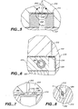
- Figs. 1, 2 and 11 the system allowing fixed position mounting of the elements is shown in a perspective view.
- the lasers (not shown) produce illumination light, which is directed through an optical fiber, linked to the system by mounts.
- the first, second and third optical fiber mounts 11, 12, and 13 respectively each receive an optical fiber bringing illumination light from one laser.
- Optical fiber mounts are mounted on plate 19 that is secured to platform 20 by braces 22. Braces 22 ensure that plate 19 will be maintained in a fixed position.
- Light from optical fibers coupled to mounts 11, 12, and 13 is directed through illumination refracting optics.
- a series of prisms are used to combine the illumination beams into illumination light having specific properties. At the point of illumination, it is preferred that the illumination beams be elliptical, concentrating the illumination energy at the central location of the core of the flow stream. As the light is directed through prisms 23, 24, 25 and 26 the illumination beams are differentially refracted by the prism such that the illumination beams are redirected and aligned at the illumination location within a flow cell. Prisms 23, 24, 25 and 26 are mounted on plate 21, which is secured to platform 20 by braces 27. The mounts for both the laser couplings and the prisms may be adjusted once at the setup of the system, positioning each element in a fixed location.
- This may be performed by either adjusting the mounts for each element, or repositioning the plate on which elements are mounted so that a number of elements are moved together.
- the prisms are less sensitive to angular misalignment and are more thermally stable. Both of these features aid in allowing set position of this element.
- Illumination lens mount 31 is positioned on arm 60 secured to face 61 on lens positioning stage 33.
- Micrometer 35 extends to arm 60 to allow movement of lens mount 31 along the z-axis.
- Plate 61 is movable by micrometer 34 to allow movement of the illumination lens mount along the y-axis.
- Micrometer 36 is mounted through lens positioning block 33 to allow movement of lens mount 31 along the x-axis. In combination, positioning micrometers 34, 35, 36 allow lens mount 31 to be repositioned in the x, y, and z directions.
- Lens mount 31 is mounted on block 33, which is mounted on platform 20. Plates 19 and 21 and block 33 are each at a separate location on platform 20. Each of these elements may be separately adjusted initially at installation for alignment.
- the focused illumination beams pass through the illumination lens held in lens mount 31 and through the optical analysis region of the flow channel in flow cell 41. As particles pass through the flow channel and cross the illumination light beams, light will be scattered and fluorescence will be excited. Scattered light will be detected by forward light scatter detector 43. Emitted fluorescence as well as large angle scattered light will be collected by emission collection optics.
- Flow cell 41 and forward light scatter detector 43 are mounted on plate 39. Plate 39 is held on platform 20 by brace 29. Platform 20 is supported on feet 46. Isolation mounts 45 allow mounting of platform 20.
- the optics for bringing in light, redirecting the beams into the desired illumination orientation, collection of the scattered and emitted fluorescence are all held in a fixed position.
- the flow cell is also held in a fixed position.
- fixed location refers to an element which does not have a means for user adjustment. This element at a fixed location would be aligned initially (generally at instrument set up) and not require further alignment.
- “Illumination input optics” refers to optical elements that allow introduction of light to a system (e.g. optical fiber mounts).
- Illumination beam directing optics are optical elements that redirect and reshape the illumination beams (e.g. serial prisms). Illumination beam directing optics may or may not include a focus lens.
- Light collection optics refers to optical elements disposed to collect emitted or scattered light from the flow channel.
- such optics generally include a fluorescence and wide angle scatter collection lens and a forward scatter detector.
- the ability to have a fixed position illumination input optics, illumination beam directing optics, flow cell, and light collection optics depends on two factors. The first is the ability to direct light with elements that will not routinely go out of alignment. The second is the ability to fix the location of the flow cell, allowing the distance between the flow channel, the illumination optics and collection optics to remain constant. This allows the illumination optics and the collection optics to also be located at fixed locations. It further allows the flow cell to be joined to the light collection optics in a way that minimizes loss of the collected light.
- the flow cell 41 is shown in front and side cross section respectively.
- the sheath flow tubes are not shown in these views.
- sample delivery tube would be positioned such that the sample is introduced just before the neckdown region (the region adjacent to the beginning of the flow channel) as shown in Fig. 3.
- the two sheath flow delivery tubes provide sheath flow in an even, pulse free flow.
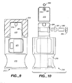
- the flow cell 41 is shown comprised of flow cell body 230, cuvette 210, nozzle key 214, and flow cell base plate 220.
- Flow cell body 230, cuvette 210 and flow cell base plate 220 are joined together to form a single unit that may be secured in a fixed location by bolts extending through holes 209 onto a flow cytometer instrument (e.g. by bolting the flow cell onto a fixed position plate).
- the nozzle key 214 is not fixed and may be inserted into a location such that the nozzle is at the end of the flow cannel.
- the nozzle key could be subsequently removed, cleaned (e.g. sonicated) and reinserted.
- the fitting 233 containing the sample input tube also might be periodically removed and reattached. This allows the remaining portions of the flow cell to be in a fixed location within a flow cytometer.
- the upper portion of the flow cell is the flow cell body 230, which receives both the sheath flow tubes and the sample delivery tube 202.
- the sheath flow liquid is delivered in tubes joined to fluid input body though ports 206, 208.
- the flow is delivered such that the sheath fluid surrounds a core of the sample stream as liquid passes through the flow channel 212.
- the sheath fluid carries the core stream through a converging channel in flow cell body 230 and into the flow channel 212 in cuvette 210.
- the flow cell body 230 has an open top end through which the sample tube and oscillator are introduced. Inserted through the open top end is sample tube inlet fitting 233 and transducer plunger 232. Plunger 232 is retained on boss 202 on flow cell body 230. A tube (not shown) held by fitting 233 introduces a sample liquid through a passage in fitting 233. This passage is joined to sample delivery tube 202 such that liquid flows through the passage, into sample delivery tube 202 and into a passage within the flow cell body.
- the sample delivery tube 202 terminates at an open end proximate to the flow channel 212 that extends through cuvette 210. At this location the sample flowing through sample delivery tube 202 is surrounded by sheath flow fluid, forming the sample into a core in the flow stream as the stream moves through flow channel 212.
- the flow stream flows through flow channel 212 in cuvette 210 and exits at nozzle 216.
- the length of flow channel H1 is sufficiently long to ensure fully developed flow in the optical analysis region H2 under all operating conditions. In the illustrated system a length of 8-15 mm is sufficient for a fully developed flow.
- Sidewalls 213 extend about three sides of nozzle key 214, allowing registration of the nozzle key 214 in place. At the point of exit, the sample stream flow velocity increases as the sample exits the narrower nozzle opening.
- Nozzle 216 is mounted on nozzle key 214, positioned at a registered location at the end of cuvette 210.
- the bottom side of nozzle key 214 rests on flow cell base platform 222 on flow cell base plate 220.
- H1 indicates a height of the cuvette between the flow cell body 230 and the nozzle key 214. This is the location where illumination beams are directed through flow channel 212. Close tolerances between the nozzle and the registration features insure that the direction of the stream does not change after a nozzle has been removed and replaced by the user.
- Fig. 5 shows a detail of the nozzle key 214 and cuvette 210.
- Nozzle key 214 has a nozzle key card 213 affixed to the top surface of the nozzle key 214.
- the nozzle 216 is positioned on nozzle key card 213 on the nozzle key 214 such that the nozzle 216 is positioned at a selected location in the cross section of flow channel 212 when nozzle key 214 is inserted into cuvette 210.
- nozzle key 214 is held between flow cell base platform 222 and the top surface of cuvette. The stream generated by flow through nozzle 216 flows into passage 218.
- nozzle 210 The detail of the nozzle is shown in Fig. 7.
- Cuvette 210 is shown having a flow channel 212.
- nozzle 216 At a terminus of flow channel 212 nozzle 216 is positioned.
- Nozzle 216 is shaped like a truncated funnel, producing a more stable flow stream.
- O-ring 260 seals nozzle key card 273 to cuvette 210 when nozzle key 214 is inserted in its registered position.
- the stream in air which flows from nozzle 216 then passes through passage 218.
- the sample could be collected here or the stream could be separated into droplets, allowing subsequent charging and sorting of droplets.
- a drop drive piston 240 may be used. Signals for the power and operation of the drop drive piston 240 may be sent through transducer electrical terminal 235. The electronic signal is sent to drop drive piezo element 234 held in transducer plunger 232. Drop drive piezo element 234 oscillates drop drive piston 240, sending oscillating pressure waves through the incompressible sheath flow fluid.
- Previous systems have used vibration (as from a piezoelectric crystal) of the nozzle cuvette, or flow cell to generate droplets.
- the droplets generated are separated by the wavelength of the vibration. This allows division of the flow into individual droplets for sorting.
- the vibration of either the nozzle or the entire flow cell could have negative effects on the consistency of illumination and light collection if the vibration causes the relative distance from the flow channel and the illumination focus or light collection focus to change. This effect is more pronounced in stream-in-air optical interrogation.
- droplet generation originates from a displacement type oscillator near the source of the sheath flow. It has been found that the pressure waves are transmitted through the largely incompressible flow fluid and effectively generate the desired droplets.
- the side cross-section shows detail of the key nozzle 214 as it is secured in place.
- key 214 is shown having nozzle key grip 270.
- Nozzle key 214 has a passage 218 defined by surface 254 and surface 256.
- Nozzle key plunger 281 biases the nozzle against the sidewall of the cuvette, holding the nozzle in a registered position.
- the detail of the nozzle section shown in Fig. 6 shows the insertion of the nozzle between cuvette 210 and flow cell base platform 222, holding nozzle key 214 in a position such that nozzle 216 is registered against the terminus of channel 212 extending through cuvette 210, by the cell base platform 222.
- Nozzle key plunger 281 provides a biasing pressure to retain nozzle key 214 in position. Shoulder 311 on nozzle key 214 is appressed against a surface of cuvette 210 when the nozzle key is fully inserted. This positions the nozzle at a registered position. The nozzle is prevented from being inserted too far, preventing damage to back wall 254.
- nozzle key 214 is shown with nozzle 216 positioned on nozzle key card 273.
- Label 271 affixed to the bottom of the card allows identification of the specific nozzle card used.
- Nozzle key plunger 281 provides a biasing force of the nozzle key 214 against the side walls of cuvette 210.
- Nozzle key grip 270 allows a user to grip nozzle key 214 and remove it from cuvette 210. In this way if the nozzle were to become clogged, the nozzle could be simply removed, cleaned (e.g. sonicated) and replaced.
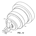
- nozzle key is shown in exploded view.
- the nozzle key plunger 281 is inserted through the nozzle key 214.
- Spring 282 retained within nozzle key 214 by nozzle key spring plug 283, provides a biasing force on plunger 281.
- Plug 283 is retained on plug retainer 284.
- Nozzle key card is affixed on the top of nozzle 214.
- O-ring 260 fits into groove 261 to provide a sealing force of the key card 273 to the cuvette when nozzle key 214 is inserted into the cuvette.
- the use of a cuvette for the optical analysis of the stream allows for a lower excitation power requirements and greater efficiency of the collection optics.
- the cuvette presents a stationary target with a flat interface for the incoming laser light from the illumination optics. Therefore, less light is lost to reflection and refraction. Because less light is lost, lower laser power is required.
- These features also make the collection of light more efficient. Less light is lost due to refraction of light from the stream to the light collection optics.
- the material transition from the stream to the collection optics can avoid the transition from liquid to air, with the attendant high index of refraction eliminated.
- the use of the nozzle that may be inserted into a registered position allows fixing the position of the flow cell, illumination optics and the light collection optics.
- One advantage to this configuration is the elimination of wear and tear on the flow cell. When the flow cell is removed, it is possible that the surfaces through which light pass on the flow cell could become scratched or marred such that light collection or transmission to or from the illumination channel is altered. This is mitigated by fixing the flow cell in place and not requiring the flow cell to be moved or manipulated.
- each material through which light passes will have a characteristic index of refraction.
- Light will be refracted when it passes from a medium having a first index of refraction to a medium having a second index of refraction.
- a major problem encountered in prior systems that optically analyze in a stream in air is the high index of refraction between the stream of liquid and air. This, coupled with illumination light losses due to the gross cylindrical nature of the stream in air, requires higher excitation power than is required in a cuvette system.
- losses to refraction also occur in the transition from the cuvette to air material transition as emitted fluorescence moves from the cuvette, into air and subsequently into the collection lens. Fluorescence excited in a liquid moving through the flow channel is collected by a collection lens on one side of the flow channel. If the flow cell is fixed in location, the light collection optics may be physically joined to the cuvette. This reduces the refraction at the material transition from the cuvette to the collection lens.
- the cuvette 210 is joined to the emission collection lens in housing 50.
- the nozzle key 214 is inserted into position such that the nozzle is positioned at the end of the flow channel. This is shown in Fig. 13.
- the flow channel 212 is shown extending through the cuvette 210.
- the cuvette 210 is linked to an initial optical element 52 by a gel 290.
- Light is collected by lenses in housing chamber 51.
- One such collection lens is disclosed in U.S. Pat. Appln. Ser. No. 09/934,741 entitled "Flow Cytometry Lens Systems".
- Nozzle key 214 is inserted and registered against cuvette 210. In one direction this registration is effected by biasing the key by nozzle plunger 281, holding the nozzle card in position laterally.
- the sidewalls 213 of the cuvette 210 extend below the exit plane of the cuvette (i.e. the plane containing the exit of the end of the flow channel). This allows for a larger numerical aperture ⁇ for the collection of emitted fluorescence and for forward scatter.
- the lower sidewalls 213 permit a lower entrance point for the laser beams, enabling the closest possible location of the optical interrogation region to the nozzle.
- the optical interrogation is 700 nm from the nozzle opening. This configuration ensures minimization of the delay time and least time delay error between the lowest laser illumination of the stream (target detection) and the droplet charging.
- the cuvette In prior flow cytometers in which optical analysis of a sample occurs in a cuvette channel, the cuvette would be of a block shape and the sidewalls would terminate at a bottom surface of the cuvette. In this configuration the illumination must occur a significant distance from the bottom of the cuvette, in order for efficient light collection of emitted fluorescence. If illumination occurs too close to the bottom of the cuvette, much of the potentially collectable fluorescent light will be lost from the bottom of the cuvette, which would refract the light away from the collection lens. To avoid this problem, the light collection would occur a significant distance from the bottom of the cuvette and thus a significant distance from the end of the flow channel.
- the separation distance of the detection of targets and the nozzle is critical for determining drop delay and properly charging and deflecting droplets of interest. It is also critical towards avoiding time delay errors, which reduce sorting performance.
- the geometry of the channel also allows for more efficient illumination and light collection.
- a rectangular cross sectional channel is used. The shorter side of the channel faces the illumination light and the longer side of the channel faces the collection lens. This allows collection from the area of the longer side of the channel. This presents a higher numerical aperture for collection. In Fig. 8 this is indicated by angle ⁇ . Collection from a higher numerical aperture allows more efficient collection of emitted light and greater sensitivity. This greater sensitivity enables use of lower power lasers. In addition, this wide viewing window allows keeping the cross-sectional area relatively small. This reduces the volumetric consumption of sheath flow required for the system.
- the system shown in Figs. 1 and 2 would be contained in a housing (not shown). This housing would prevent light from the area surrounding the system from entering the system.
- Sorting droplets requires precise coordination of the detection of a target of interest, encapsulation of the target into a droplet during droplet formation, charging the droplet and sorting the droplet by passing the charged droplet containing the target of interest between two charged deflection plates.
- the flow of fluid into the flow cell is kept pulse free so that the perturbations of the fluid are minimized. This allows the general condition of directional stream in air stability.
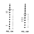
- the drop drive causes a leading order effect in which the flow stream-in-air, after flowing from the nozzle, breaks into a train of large droplets having a characteristic diameter of the same order of magnitude as the jet diameter, as shown in Fig. 15a.
- smaller droplets 306a typically form between the larger "parent" droplets 304a.
- the smaller droplets are referred to as "satellite droplets”. It is advantageous to have a stream condition in which no satellites form, or in which the satellite droplets that do form quickly merge into the parent droplets.
- the satellite droplets are significantly smaller, and hence have lower masses, than the parent droplets.
- sorting is accomplished by selectively charging droplets.
- the droplets then pass through an electric field that deflects the path of the charged droplets so that the charged droplets are deflected from the rest of the droplet stream.
- the deflected droplets are deflected into a separate collection container for later use or analysis.
- the required magnitudes of both the droplet charging and electric field potentials of the charging plates are selected to provide the needed deflection of the parent droplets.
- the smaller satellite droplets that are deflected by the charged deflection plates may be so light that the particles are directed out of the flow stream and onto the charging plates.
- the resulting wetting of the charging plates may adversely affect system performance and require interruption of the use of the system to dry and clean the deflection plates.
- the deflection of satellite droplets could present biohazard risks, especially if the satellite droplets form aerosol droplets that remain suspended in the air.
- a detail of the cross section of the cuvette 210 shows the flow channel 212 with a circle indicating the nozzle opening 294.
- the center 292 of nozzle opening 294 is positioned off center from the cross sectional center of flow channel 212. A small lateral adjustment of the centering of the nozzle in the flow channel provides a more favorable condition for merger of the satellite droplets with the parent droplets.
- the nozzle is purposefully misaligned with respect to the center of the flow channel. This misalignment may be achieved by machining .001 inch from the nozzle registration feature that locates the nozzle in the long dimension of the cuvette channel (e.g. the sides of the nozzle card).
- the present system allows precise location of an insertable nozzle card. The ability to precisely and repeatably locate the nozzle allows design of the nozzle card such that the nozzle is off from the flow channel center.
- the nozzle location is fully constrained by hard features on the nozzle that register directly against the cuvette (or flow cell) such that the nozzle orientation is always fixed in three dimensions with respect to the exit of the cuvette channel.
- the registration of the nozzle in this manner minimizes tolerance stack up.
- the limiting factors of this approach are the manufacturing tolerances associated with manufacturing the nozzle and the cuvette. State of the art manufacturing procedures allow nozzle location to +/- .0012" (+/- 30.48 ⁇ m) in the plane of the channel. Given these manufacturing tolerances, nozzle-to-nozzle stream performance has proven to be consistent. A given nozzle will always register against a given cuvette in the same manner, ensuring a consistent stream direction and droplet formation pattern.
- the theoretical model of droplet formation indicates that an axisymetric flow stream excited by a fundamental frequency in the range of the spontaneous droplet frequency will break up into a droplet chain in which the satellite droplets never merge with the parent droplets. This implies that deviation from perfect axisymetry could allow for more optimal satellite droplet merging conditions.
- the nozzle is adjusted laterally in the long dimension. This is generally preferred, as it produces the smallest variation in the path for particles within the flow stream. This minimizes the difficulty in timing the delay between detection in the channel and charging and sorting droplets after the droplets have passed through the nozzle. It is also possible to have the displacement in the shorter dimension or displace the centering in both the long and the sort dimensions (i.e. displace on a diagonal from the cross sectional center of the stream).
- an image of the stream shows droplet formation in a system in which the center of the nozzle opening is closely aligned with the center of the flow channel.
- the stream has begun to break into individual droplets.
- Height A marks the distance from the formation of the first droplet broken from the flow stream to the area where the satellite droplets have combined into the parent droplets. It would be preferred that droplet deflection not occur before this location.
- Parent droplet 304a and satellite droplet 306a are identified close to the location of droplet formation at the top of height A.
- a merging parent and satellite droplet 305a are identified close to the bottom of height A. Eight or more droplet wavelengths are required before the parent droplet and the satellite droplets have merged.
- FIG. 15b an image of the droplet formation pattern in which the nozzle has been misaligned is shown. This is the misalignment shown in Fig. 8, in which a rectangular flow channel is used. The dimensions of the flow channel in this embodiment is 250 um by 160 um. The nozzle is deliberately shifted 25.4 um off of the centerline of the cuvette in the long axis of the cuvette.
- height B is a height from the location of a droplet formation to a location where the droplets do not show any satellite droplets.
- Satellite droplet 306b, shown just after droplet break-off point, and parent droplet 304b are shown. A merging parent droplet with a satellite droplet 305b is just below. In three droplet wavelengths the parent droplets have merged with the satellite droplets
- the nozzle opening is a truncated tapered cone.
- a card is affixed to a nozzle key such that the nozzle is in a precisely registered location when the card is inserted into the flow cell.
- the nozzle may take many shapes and geometries. For example, an elongate nozzle opening may be preferable in some applications to a round opening.
- the nozzle may be a lengthened truncated cone, extending downstream from the flow stream direction. In this way the transition from the width of the flow channel to the nozzle may be made less abrupt, and could be a continuous graded tapering to the nozzle opening.
- the substrate on which the nozzle opening is formed may use a number of different designs.
- the fixed flow cell with nozzle key may be adapted into present systems in which the illumination optics and light detection optics may be aligned.
- the fixed flow cell may be used with either fixed location light collection optics (e.g. fluorescent light collector and light scatter collectors) or a fixed location illumination optics.
- Other optical elements within such systems would still require routine adjustment.
- Such systems would retain the advantage of having a fixed position flow cell that does not require to be removed or adjusted.
- the cuvette may not be physically coupled to the light collection optics.
- Such embodiments could have all of the attendant optics (illumination optics, light collection optics, and scatter detection optics) in a fixed location or have some or all of these elements mounted on an adjusting mounts.
- the droplet drive may be generated by an oscillator within the flow cell, allowing transfer of the oscillating pulse to the largely incompressible fluid.
- the droplet drive may be generated by more conventional means, such as vibrating the nozzle, cuvette or vibrating the entire flowcell assembly.
- the droplet drive may be generated by acoustic vibration of the stream in air.
- the flow cell body is joined to a rectangular cuvette and the nozzle is inserted at the terminus of the cuvette.
- the term "cuvette” in various embodiments, is the flow cell section through which the channel extends. This may be a separate component joined to a flow cell body. Alternatively, the cuvette may be part of the flow cell body, which may be manufactured as a single part.
- the nozzle is on a substrate that is inserted into a fixed position where it is registered against surfaces to hold the nozzle in a three-dimensional position such that the nozzle cannot angularly rotate.
- This allows the cuvette and flow to be in a fixed position.
- the illumination optics and light collection optics may also be in a fixed position.
- the cuvette may be physically joined to the collection lens. It is also foreseen that a flow cell could be made in which the nozzle is a fixed part of the cuvette and the cuvette and nozzle are removed and inserted together. Precision guides could be used to precisely position the cuvette at the required location needed for alignment with illumination optics.
- the cuvette could be removed, sonicated or otherwise treated to clear a clog in the nozzle or flow channel, and replaced into a precise position. Because the droplet generator is in the flow cell body, the cuvette and nozzle could be removed and reinserted without having to reconnect to a vibration generator.
- the invention was illustrated in a system in which multiple lasers are directed into the system using optical fibers.
- the beams are redirected and shaped using refractive optics. It is envisioned that a single laser or any number of lasers may be used.
- the lasers could be positioned on the platform and held in a fixed position (e.g. using diode lasers). It is also possible to employ non-laser light sources such as arc lamps.
- the conventional use of steering mirrors and dichroic mirrors could be used to direct and shape the illumination beams.
- spatial filters, long or short pass filters, apertures or other optics may be employed to block stray light and reduce transmission of undesired wavelengths. Systems employing conventional optics are disclosed in the references cited herein, which are collectively incorporated by reference.
- the flow channel in the present illustration is rectangular. In other embodiments, a round flow channel or other geometries are envisioned.
- nozzle is on a removable key. However, the nozzle could also be precision aligned and affixed (by sonic welding, adhesive attachment, etc.) to the end of the flow channel. Such a system would require some means of back-flushing the nozzle to clear clogs.
- the illustrated system discloses the use of the flow cell in a sorting flow cytometer. While the present invention provides numerous advantages when employed in a sorting cytometer, it is also considered that disclosed technology could be used in non-sorting analytical cytometers.
- the interior of the flow cell could be coated to prevent adhesion of cells, cell fragments or other compounds. Such a treatment would be selected to not be affected by the flow fluid.
- the flow cell is not removed but may be selectively flushed.
- the sheath flow system may be designed to allow for system flushing. If fluid is introduced through a first sheath flow port and removed through a second port, flow conditions would direct the flow in a vortex through the flow cell interior, washing all elements.
- any clog is likely to occur in the nozzle, which may be removed and cleaned. If the channel clogs, the nozzle may be removed and the channel cleared with back pressure.
- the present invention allows development of a system in which the user does not have to perform any routine optical alignment procedure.
- the user could remove and replace the nozzle without further alignment of the stream direction or optics.
- the analysis is effected in a cuvette, with the attendant sensitivity allowed by analysis in a cuvette.
- Sorting occurs in the steam in air, allowing sorting in the conventional manner.
- the relatively low velocity of the core stream in the analysis region is advantageous for analysis of targets.
- the stream is then accelerated by the nozzle, to allow for high speed sorting.
Landscapes
- Chemical & Material Sciences (AREA)
- Biochemistry (AREA)
- General Physics & Mathematics (AREA)
- Health & Medical Sciences (AREA)
- Life Sciences & Earth Sciences (AREA)
- Analytical Chemistry (AREA)
- Dispersion Chemistry (AREA)
- General Health & Medical Sciences (AREA)
- Physics & Mathematics (AREA)
- Immunology (AREA)
- Pathology (AREA)
- Investigating, Analyzing Materials By Fluorescence Or Luminescence (AREA)
- Optical Measuring Cells (AREA)
- Investigating Or Analysing Biological Materials (AREA)
- Investigating Or Analysing Materials By The Use Of Chemical Reactions (AREA)
Applications Claiming Priority (2)
| Application Number | Priority Date | Filing Date | Title |
|---|---|---|---|
| US10/259,332 US7201875B2 (en) | 2002-09-27 | 2002-09-27 | Fixed mounted sorting cuvette with user replaceable nozzle |
| US259332 | 2002-09-27 |
Publications (3)
| Publication Number | Publication Date |
|---|---|
| EP1403633A2 true EP1403633A2 (de) | 2004-03-31 |
| EP1403633A3 EP1403633A3 (de) | 2004-04-07 |
| EP1403633B1 EP1403633B1 (de) | 2012-07-04 |
Family
ID=31977898
Family Applications (1)
| Application Number | Title | Priority Date | Filing Date |
|---|---|---|---|
| EP03020445A Expired - Lifetime EP1403633B1 (de) | 2002-09-27 | 2003-09-12 | Festmontierte Sortierungsküvette mit vom Nutzer austauschbarer Düse |
Country Status (3)
| Country | Link |
|---|---|
| US (3) | US7201875B2 (de) |
| EP (1) | EP1403633B1 (de) |
| JP (1) | JP4585190B2 (de) |
Cited By (15)
| Publication number | Priority date | Publication date | Assignee | Title |
|---|---|---|---|---|
| EP2207025A3 (de) * | 2009-01-13 | 2010-12-08 | Becton, Dickinson and Company | Küvette für Flusspartikelanalysegerät |
| WO2016035284A1 (en) * | 2014-09-05 | 2016-03-10 | Sony Corporation | Droplet sorting device, droplet sorting method and program |
| US9879221B2 (en) | 2000-11-29 | 2018-01-30 | Xy, Llc | Method of in-vitro fertilization with spermatozoa separated into X-chromosome and Y-chromosome bearing populations |
| US10100278B2 (en) | 2003-03-28 | 2018-10-16 | Inguran, Llc | Multi-channel system and methods for sorting particles |
| US10132735B2 (en) | 2012-03-30 | 2018-11-20 | Sony Corporation | Microparticle sorting device and method of optimizing fluid stream therein |
| US10208345B2 (en) | 2000-05-09 | 2019-02-19 | Xy, Llc | Method for producing high purity X-chromosome bearing and Y-chromosome bearing populations of spermatozoa |
| US10241025B2 (en) | 2013-01-28 | 2019-03-26 | Sony Corporation | Microparticle sorting device, and method and program for sorting microparticles |
| US10309892B2 (en) | 2014-02-13 | 2019-06-04 | Sony Corporation | Particle sorting device, particle sorting method, program, and particle sorting system |
| US10309891B2 (en) | 2013-10-16 | 2019-06-04 | Sony Corporation | Particle sorting apparatus, particle sorting method, and program |
| US10605714B2 (en) | 2015-10-19 | 2020-03-31 | Sony Corporation | Image processing device, fine particle sorting device, and image processing method |
| WO2021236466A1 (en) * | 2020-05-19 | 2021-11-25 | Life Technologies Corporation | Nozzle sealing and unclog station for a flow cytometer |
| US11193874B2 (en) | 2012-03-30 | 2021-12-07 | Sony Corporation | Micro-particle sorting apparatus and method of determining a trajectory of an ejected stream carrying micro-particles |
| US11230695B2 (en) | 2002-09-13 | 2022-01-25 | Xy, Llc | Sperm cell processing and preservation systems |
| CN114248540A (zh) * | 2020-09-21 | 2022-03-29 | 三星显示有限公司 | 气体干燥器及具备该气体干燥器的溶剂去除装置 |
| EP4134655A1 (de) * | 2021-08-10 | 2023-02-15 | Becton, Dickinson and Company | Auslassstutzen zur verminderung von blasen an der grenzfläche einer durchflusszelle und durchflusszytometer und verfahren zu deren verwendung |
Families Citing this family (152)
| Publication number | Priority date | Publication date | Assignee | Title |
|---|---|---|---|---|
| ATE298084T1 (de) * | 1997-01-31 | 2005-07-15 | Horticulture & Food Res Inst | Optische vorrichtung und methode |
| US20020144905A1 (en) * | 1997-12-17 | 2002-10-10 | Christian Schmidt | Sample positioning and analysis system |
| US7244349B2 (en) * | 1997-12-17 | 2007-07-17 | Molecular Devices Corporation | Multiaperture sample positioning and analysis system |
| CA2316966C (en) * | 1997-12-17 | 2008-04-08 | Horst Vogel | Positioning and electrophysiological characterization of individual cells and reconstituted membrane systems on microstructured carriers |
| US6149867A (en) | 1997-12-31 | 2000-11-21 | Xy, Inc. | Sheath fluids and collection systems for sex-specific cytometer sorting of sperm |
| US6071689A (en) | 1997-12-31 | 2000-06-06 | Xy, Inc. | System for improving yield of sexed embryos in mammals |
| EP2283848A1 (de) | 1998-07-30 | 2011-02-16 | Xy, Llc | Pferdesystem für die künstliche Befruchtung ohne chirurgischen Eingriff |
| US7208265B1 (en) | 1999-11-24 | 2007-04-24 | Xy, Inc. | Method of cryopreserving selected sperm cells |
| CA2411462A1 (en) * | 2000-06-12 | 2001-12-20 | Colorado State University Research Foundation | Integrated herd management system utilizing isolated populations of x-chromosome bearing and y-chromosome bearing spermatozoa |
| US7067046B2 (en) * | 2000-08-04 | 2006-06-27 | Essen Instruments, Inc. | System for rapid chemical activation in high-throughput electrophysiological measurements |
| US7270730B2 (en) * | 2000-08-04 | 2007-09-18 | Essen Instruments, Inc. | High-throughput electrophysiological measurement system |
| US7713687B2 (en) | 2000-11-29 | 2010-05-11 | Xy, Inc. | System to separate frozen-thawed spermatozoa into x-chromosome bearing and y-chromosome bearing populations |
| US8486618B2 (en) | 2002-08-01 | 2013-07-16 | Xy, Llc | Heterogeneous inseminate system |
| MXPA05001100A (es) | 2002-08-01 | 2005-04-28 | Xy Inc | Sistema de separacion de baja presion para celulas de esperma. |
| MXPA05001654A (es) | 2002-08-15 | 2005-10-18 | Xy Inc | Citometro de flujo de alta resolucion. |
| US7201875B2 (en) * | 2002-09-27 | 2007-04-10 | Becton Dickinson And Company | Fixed mounted sorting cuvette with user replaceable nozzle |
| US20040151635A1 (en) * | 2003-01-31 | 2004-08-05 | Leproust Eric M. | Array fabrication using deposited drop splat size |
| CA2566749C (en) | 2003-05-15 | 2017-02-21 | Xy, Inc. | Efficient haploid cell sorting for flow cytometer systems |
| JP2007506106A (ja) * | 2003-09-19 | 2007-03-15 | サーノフ コーポレーション | 浮遊微粒子を分類する方法および装置 |
| FI116774B (fi) * | 2004-01-08 | 2006-02-28 | Dekati Oy | Menetelmä ja laitteisto pienten hiukkasten koon kasvattamiseksi |
| MXPA06011345A (es) | 2004-03-29 | 2006-12-15 | Monsanto Technology Llc | Suspensiones de espermatozoides para usar en inseminacion. |
| BRPI0513685A (pt) | 2004-07-22 | 2008-05-13 | Monsanto Technology Llc | processo para enriquecimento de uma população de células de esperma |
| ES2555126T3 (es) * | 2004-07-27 | 2015-12-29 | Beckman Coulter, Inc. | Mejora de la discriminación en citometría de flujo con transformación geométrica |
| US7618770B2 (en) | 2005-07-29 | 2009-11-17 | Xy, Inc. | Methods and apparatus for reducing protein content in sperm cell extenders |
| US9476856B2 (en) | 2006-04-13 | 2016-10-25 | Advanced Liquid Logic, Inc. | Droplet-based affinity assays |
| US7901947B2 (en) | 2006-04-18 | 2011-03-08 | Advanced Liquid Logic, Inc. | Droplet-based particle sorting |
| US10078078B2 (en) | 2006-04-18 | 2018-09-18 | Advanced Liquid Logic, Inc. | Bead incubation and washing on a droplet actuator |
| US8716015B2 (en) | 2006-04-18 | 2014-05-06 | Advanced Liquid Logic, Inc. | Manipulation of cells on a droplet actuator |
| US7439014B2 (en) | 2006-04-18 | 2008-10-21 | Advanced Liquid Logic, Inc. | Droplet-based surface modification and washing |
| US8809068B2 (en) | 2006-04-18 | 2014-08-19 | Advanced Liquid Logic, Inc. | Manipulation of beads in droplets and methods for manipulating droplets |
| JP2008224342A (ja) * | 2007-03-12 | 2008-09-25 | Rion Co Ltd | フローセル、フローセルの製造方法及び粒子測定装置 |
| WO2008128213A1 (en) * | 2007-04-12 | 2008-10-23 | Regents Of The University Of Minnesota | Systems and methods for analyzing a particulate |
| US7821631B1 (en) * | 2007-04-20 | 2010-10-26 | Shervin Javadi | Architecture of laser sources in a flow cytometer |
| US7880108B2 (en) | 2007-10-26 | 2011-02-01 | Becton, Dickinson And Company | Deflection plate |
| EP2157599A1 (de) * | 2008-08-21 | 2010-02-24 | Nederlandse Organisatie voor toegepast- natuurwetenschappelijk onderzoek TNO | Verfahren und Vorrichtung zur Identifikation biologischer Materialien |
| CN201404734Y (zh) * | 2009-04-28 | 2010-02-17 | 厦门市毕恩生物技术有限公司 | 底部控制式标本过滤容器 |
| CN102762990B (zh) * | 2009-12-04 | 2014-10-29 | 生命技术公司 | 用于声学流式细胞计量术的装置、系统、方法和计算机可读介质 |
| JP5437148B2 (ja) * | 2010-04-23 | 2014-03-12 | ベイバイオサイエンス株式会社 | フローサイトメータおよびセルソータ |
| CN105044376A (zh) * | 2010-05-05 | 2015-11-11 | 贝克曼考尔特生物医学有限责任公司 | 装置耦合件、电动机与装置耦合件以及将轴固定到装置耦合件的凹入部分的方法 |
| JP2014174139A (ja) * | 2013-03-13 | 2014-09-22 | Sony Corp | 流路デバイス、粒子分取装置、粒子流出方法、及び粒子分取方法 |
| US9446159B2 (en) | 2013-10-03 | 2016-09-20 | Becton, Dickinson And Company | Flow cytometer biosafety hood and systems including the same |
| WO2015061216A1 (en) * | 2013-10-21 | 2015-04-30 | Cytoflow, Llc | Cytometer flowcell |
| US9835542B2 (en) * | 2013-12-17 | 2017-12-05 | Dna Medicine Institute, Inc. | Optical block |
| JP6189743B2 (ja) * | 2013-12-26 | 2017-08-30 | シスメックス株式会社 | 血中フィラリア幼虫の検出方法、血液分析装置、及びコンピュータプログラム |
| US9575050B2 (en) | 2014-04-21 | 2017-02-21 | Becton, Dickinson And Company | Slider tape sealing cartridge for adjustably sealing a flow cytometer sample manipulation chamber |
| CN208488366U (zh) * | 2014-11-17 | 2019-02-12 | 贝克顿·迪金森公司 | 流式细胞仪流动池比色皿及包括其的流式细胞术系统 |
| EP3227662B1 (de) | 2014-12-04 | 2023-07-12 | Becton, Dickinson and Company | Durchflusszytometriezellsortierungssysteme und verfahren zur verwendung davon |
| US9709769B2 (en) | 2014-12-10 | 2017-07-18 | Becton, Dickinson And Company | Methods for optically aligning light collection components and optically aligned light collection systems thereof |
| EP3259574B1 (de) | 2015-02-18 | 2024-03-27 | Becton, Dickinson and Company | Optische erfassungssysteme und verfahren zur verwendung davon |
| AU2016222728B2 (en) | 2015-02-27 | 2018-09-27 | Hycor Biomedical, Llc | Apparatuses and methods for suspending and washing the contents of a plurality of cuvettes |
| EP3311135B1 (de) | 2015-06-17 | 2023-11-01 | Becton, Dickinson and Company | Streukappenanordnung für optischen detektor mit abnehmbarem streubalken und verfahren zur verwendung davon |
| JP6856635B2 (ja) | 2015-10-13 | 2021-04-07 | オメガ バイオシステムズ インコーポレイテッド | マルチモードの蛍光撮像フローサイトメトリシステム |
| US20190086319A1 (en) | 2016-03-10 | 2019-03-21 | Becton, Dickinson And Company | Methods of evaluating a cellular sample for her-2/neu expression and compositions for practicing the same |
| KR20180129832A (ko) | 2016-03-17 | 2018-12-05 | 비디 바이오사이언시스 | 고효율 형광 유세포분석기를 사용하는 세포 선별 |
| CN118670959A (zh) | 2016-04-15 | 2024-09-20 | 贝克顿·迪金森公司 | 封闭式小滴分选器以及其使用方法 |
| ES2926537T3 (es) | 2016-04-22 | 2022-10-26 | Becton Dickinson Co | Depósito de alta densidad para la producción de matrices |
| JP7023244B2 (ja) | 2016-05-12 | 2022-02-21 | ビーディー バイオサイエンス | 画像解像度が改良された蛍光イメージングフローサイトメトリー |
| WO2018052798A1 (en) | 2016-09-13 | 2018-03-22 | Becton, Dickinson And Company | Flow cytometer with optical equalization |
| AU2017340136B2 (en) | 2016-10-03 | 2022-02-24 | Becton, Dickinson And Company | Methods and systems for determining a drop delay of a flow stream in a flow cytometer |
| US10436697B2 (en) | 2016-11-19 | 2019-10-08 | Cytek Biosciences, Inc. | Flow cytometery system with fluidics control system |
| EP3555630B1 (de) | 2016-12-14 | 2023-05-31 | Becton, Dickinson and Company | Verfahren und zusammensetzungen zum erhalt einer tuberkulosebeurteilung in einer person |
| JP7058662B2 (ja) | 2017-02-08 | 2022-04-22 | ベクトン・ディキンソン・アンド・カンパニー | 乾燥色素試薬装置、ならびにその製造及び使用方法 |
| TWI766942B (zh) | 2017-02-13 | 2022-06-11 | 美商海科生醫有限責任公司 | 透過利用瞬態和穩態間隔振動移液管來混合流體或介質的設備和方法 |
| JP7173978B2 (ja) | 2017-02-27 | 2022-11-17 | ベクトン・ディキンソン・アンド・カンパニー | 光検出システム及びその使用方法 |
| USD868991S1 (en) * | 2017-03-28 | 2019-12-03 | Becton, Dickinson And Company | Register block |
| USD869676S1 (en) * | 2017-03-28 | 2019-12-10 | Becton, Dickinson And Company | Particle sorting module |
| WO2018235383A1 (ja) * | 2017-06-21 | 2018-12-27 | ソニー株式会社 | サンプル送液装置、フローサイトメータ、およびサンプル送液方法 |
| MX2020007408A (es) | 2018-01-23 | 2020-11-11 | Becton Dickinson Co | Sistemas de oscurecimiento dinamico de deteccion de luz y metodos para su uso. |
| USD882817S1 (en) | 2018-01-30 | 2020-04-28 | Becton, Dickinson And Company | Sample container |
| USD864415S1 (en) | 2018-01-30 | 2019-10-22 | Becton, Dickinson And Company | Particle sorting system |
| USD876668S1 (en) * | 2018-01-30 | 2020-02-25 | Becton, Dickinson And Company | Particle sorting module mount |
| USD872296S1 (en) * | 2018-01-30 | 2020-01-07 | Becton, Dickinson And Company | Particle sorting module |
| US10844228B2 (en) | 2018-03-30 | 2020-11-24 | Becton, Dickinson And Company | Water-soluble polymeric dyes having pendant chromophores |
| US11275075B2 (en) | 2018-04-27 | 2022-03-15 | Becton, Dickinson And Company | Collection systems for flow cytometrically sorted samples and methods of using the same |
| WO2019209714A1 (en) | 2018-04-27 | 2019-10-31 | Becton, Dickinson And Company | Flow cytometers having enclosed droplet sorters with controlled aerosol content and methods of using the same |
| EP3811055A4 (de) | 2018-06-19 | 2022-08-10 | Becton, Dickinson and Company | Variable multiplexerschalter für detektorarrays, systeme und verwendungsverfahren dafür |
| US11099066B2 (en) | 2018-06-28 | 2021-08-24 | Becton, Dickinson And Company | Light detection systems having input and output modulators, and methods of use thereof |
| US20200056979A1 (en) | 2018-08-15 | 2020-02-20 | Becton, Dickinson And Company | Flowrate and vacuum controlled fluid management system for a flow type particle analyzer |
| US11169072B1 (en) | 2018-08-23 | 2021-11-09 | Allied Flow Inc. | Flow cell, flow chamber, particle sorting apparatus, and particle sorting apparatus cartridge |
| EP4542199A3 (de) | 2018-08-30 | 2025-07-30 | Becton, Dickinson and Company | Charakterisierung und sortierung für teilchenanalysatoren |
| EP3874254B1 (de) | 2018-10-30 | 2025-04-30 | Becton, Dickinson and Company | Teilchensortiermodul mit ausrichtungsfenster, systeme und verwendungsverfahren dafür |
| CN118980626A (zh) | 2018-12-28 | 2024-11-19 | 贝克顿·迪金森公司 | 用于对样本的荧光团进行光谱解析的方法及其系统 |
| EP3913352A4 (de) * | 2019-01-15 | 2022-03-02 | Sony Group Corporation | Mikropartikelisolierungsvorrichtung, mikropartikelisolierungssystem, tröpfchenisolierungsvorrichtung, tröpfchensteuerungsvorrichtung und tröpfchensteuerungsprogramm |
| EP3921622A4 (de) | 2019-02-08 | 2022-11-09 | Becton, Dickinson and Company | Entscheidungsmodule zum sortieren von tröpfchen, systeme und verfahren zur verwendung davon |
| US11328422B2 (en) | 2019-03-22 | 2022-05-10 | Becton, Dickinson And Company | Spectral unmixing of fluorescence imaging using radiofrequency-multiplexed excitation data |
| EP3867627B1 (de) | 2019-03-29 | 2023-10-25 | Becton, Dickinson and Company | Parameter zur verwendung bei der teilchendiskriminierung |
| US11275026B2 (en) | 2019-05-14 | 2022-03-15 | Becton, Dickinson And Company | Phase-calibration for imaging flow cytometry |
| IL287195B2 (en) | 2019-05-30 | 2025-07-01 | Becton Dickinson Co | Phase correction of multiplexed radio frequency signals |
| JP7561822B2 (ja) | 2019-07-10 | 2024-10-04 | ベクトン・ディキンソン・アンド・カンパニー | 細胞選別分類を調整するための再構成可能な集積回路 |
| US11635375B2 (en) | 2019-11-20 | 2023-04-25 | Becton, Dickinson And Company | Light detection module with adjustable sensitivity |
| US12000836B2 (en) | 2019-12-20 | 2024-06-04 | Becton, Dickinson And Company | Methods for quantitating extra-cellular vesicle surface markers, and compositions for practicing the same |
| JP7663587B2 (ja) | 2020-01-31 | 2025-04-16 | ベクトン・ディキンソン・アンド・カンパニー | 訓練ゲートを調整してフローサイトメータデータに適応させるための方法およびシステム |
| JP2023513217A (ja) | 2020-02-07 | 2023-03-30 | ベクトン・ディキンソン・アンド・カンパニー | クラスタ化波長分割光検出システム及びその使用方法 |
| US11709125B2 (en) | 2020-02-19 | 2023-07-25 | Becton, Dickinson And Company | Strobed laser excitation systems and methods of use thereof |
| JP2023516193A (ja) | 2020-02-26 | 2023-04-18 | ベクトン・ディキンソン・アンド・カンパニー | 二次光散乱検出器を有する光検出システムおよびその使用方法 |
| JP7601889B2 (ja) | 2020-02-27 | 2024-12-17 | ベクトン・ディキンソン・アンド・カンパニー | 細胞選別における飽和データ信号を識別するための方法及びそのためのシステム |
| EP4121737A4 (de) | 2020-03-17 | 2023-08-09 | Becton, Dickinson and Company | Verstärkungsangepasste verstärker zur lichtdetektion |
| WO2021211259A1 (en) | 2020-04-16 | 2021-10-21 | Becton, Dickinson And Company | Systems for light detection array multiplexing and methods for same |
| CN115735111A (zh) | 2020-04-28 | 2023-03-03 | 贝克顿·迪金森公司 | 用于对独特表型进行索引分选的方法及用于其的系统 |
| EP4143536B1 (de) | 2020-04-29 | 2025-08-20 | Becton, Dickinson and Company | Verfahren zur modulation und synchronen detektion in einem durchflusszytometer und systeme dafür |
| EP4147028A4 (de) | 2020-05-05 | 2023-11-08 | Becton, Dickinson and Company | Verfahren zur bestimmung der detektorverstärkung in einem durchflusszytometer |
| CN115997115B (zh) | 2020-05-06 | 2025-11-11 | 贝克顿·迪金森公司 | 用于表征流式细胞仪数据中的溢出扩散的方法和系统 |
| CN115867971A (zh) | 2020-05-18 | 2023-03-28 | 贝克顿·迪金森公司 | 用于检测数据中的异质性的分辨率指数及其使用方法 |
| WO2021257144A1 (en) | 2020-06-19 | 2021-12-23 | Becton, Dickinson And Company | Flow cytometer with adjustable positional offset sort deflection plates and methods of using the same |
| EP4171819A4 (de) | 2020-06-24 | 2023-12-06 | Becton, Dickinson and Company | Durchflusszytometrische tröpfchenabgabesysteme und verfahren zur verwendung davon |
| CN116171383B (zh) | 2020-06-26 | 2026-03-27 | 贝克顿·迪金森公司 | 用于照射流体流中的样品的双激励光束及其使用方法 |
| US11965813B2 (en) | 2020-08-03 | 2024-04-23 | Cytek Biosciences, Inc. | Methods and apparatus for central source pressure-based cytometer fluidics system |
| US12235201B2 (en) | 2020-09-22 | 2025-02-25 | Becton, Dickinson And Company | Methods for continuous measurement of baseline noise in a flow cytometer and systems for same |
| WO2022086666A1 (en) | 2020-10-20 | 2022-04-28 | Becton, Dickinson And Company | Flow cytometers including tilted beam shaping optical components, and methods of using the same |
| EP4237820A4 (de) | 2020-10-30 | 2024-04-03 | Becton, Dickinson and Company | Verfahren und systeme zur charakterisierung und codierung eines lichtdetektionssystems |
| JP7766690B2 (ja) | 2020-11-19 | 2025-11-10 | ベクトン・ディキンソン・アンド・カンパニー | 機械学習分析のためのサイトメトリックデータの最適なスケーリング方法及びそのシステム |
| CN116897281A (zh) | 2021-01-13 | 2023-10-17 | 贝克顿·迪金森公司 | 包括光收集增强器的流式细胞仪及其使用方法 |
| CN112924364B (zh) * | 2021-01-22 | 2024-07-23 | 贝克曼库尔特生物科技(苏州)有限公司 | 喷嘴、载体、喷嘴组件及样本处理仪 |
| CN214844688U (zh) * | 2021-01-22 | 2021-11-23 | 贝克曼库尔特生物科技(苏州)有限公司 | 用于样本处理仪的透明管组件和流式池及样本处理仪 |
| JP2024506817A (ja) | 2021-01-25 | 2024-02-15 | ベクトン・ディキンソン・アンド・カンパニー | 空間的に分離されたレーザにわたる散乱信号を使用して液滴遅延を判定するための方法及びシステム |
| CN214895849U (zh) | 2021-01-28 | 2021-11-26 | 贝克曼库尔特生物科技(苏州)有限公司 | 气泡检测装置和样本处理仪 |
| WO2022169505A1 (en) | 2021-02-04 | 2022-08-11 | Becton, Dickinson And Company | Integrated light interrogation modules and methods of use thereof |
| US12564837B2 (en) | 2021-02-05 | 2026-03-03 | Cytek Biosciences, Inc. | Integrated compact cell sorter |
| CN117120166A (zh) * | 2021-02-05 | 2023-11-24 | 厦泰生物科技公司 | 紧凑型细胞分选仪中微滴腔室的集成式空气过滤和调节 |
| WO2022203792A1 (en) | 2021-03-24 | 2022-09-29 | Becton, Dickinson And Company | Closed-system sorting flow cytometer adapters and methods of use thereof |
| US12535398B2 (en) | 2021-04-23 | 2026-01-27 | Becton, Dickinson And Company | Fluid management system for an analyzer and/or sorter type flow type particle analyzer using a detachable connector |
| CN117642619A (zh) | 2021-05-14 | 2024-03-01 | 贝克顿·迪金森公司 | 采用光谱鉴别法检测光的系统及其使用方法 |
| US12467845B2 (en) | 2021-08-10 | 2025-11-11 | Becton, Dickinson And Company | Clamps for operably coupling an optical component to a mounting block, and methods and systems for using the same |
| CN118284952A (zh) | 2021-09-21 | 2024-07-02 | 贝克顿·迪金森公司 | 基线恢复电路 |
| IL311201A (en) | 2021-11-17 | 2024-05-01 | Becton Dickinson Co | Methods for dynamic real-time adjustment of a data acquisition parameter in a flow cytometer |
| EP4437324A4 (de) | 2021-11-24 | 2025-03-05 | Becton, Dickinson and Company | Integrierte durchflusszytometriedatenqualitätskontrolle |
| WO2023140188A1 (ja) * | 2022-01-21 | 2023-07-27 | ソニーグループ株式会社 | フローサイトメータ及びフローサイトメータの液滴生成振動素子を駆動する信号の波形パラメータ設定方法 |
| EP4605727A2 (de) * | 2022-10-20 | 2025-08-27 | Cytek Biosciences, Inc. | Abnehmbare kreisförmige düse für durchflusszytometer |
| US20240312191A1 (en) | 2023-03-14 | 2024-09-19 | Becton, Dickinson And Company | Methods for determining image filters for classifying particles of a sample and systems and methods for using same |
| US20240344983A1 (en) | 2023-03-30 | 2024-10-17 | Becton, Dickinson And Company | Methods and systems for visualizing spectral signatures |
| CN121014085A (zh) | 2023-04-13 | 2025-11-25 | 贝克顿迪金森公司 | 分子诊断信号实时分类方法 |
| US20240377311A1 (en) | 2023-05-09 | 2024-11-14 | Becton, Dickinson And Company | Methods for image-based detection and sorting and systems for same |
| US20240377307A1 (en) | 2023-05-09 | 2024-11-14 | Becton, Dickinson And Company | Methods and systems for classifying analyte data into clusters |
| US20240377325A1 (en) | 2023-05-09 | 2024-11-14 | Becton, Dickinson And Company | Methods for assessing cell mitochondrial morphology and systems for same |
| US20250085212A1 (en) | 2023-09-07 | 2025-03-13 | Becton, Dickinson And Company | Integrated Optofluidic Interrogation Modules, Flow Cytometers Including the Same, and Methods of Use Thereof |
| US20250137905A1 (en) | 2023-10-27 | 2025-05-01 | Becton, Dickinson And Company | Fluid Supply Systems Having a Flow Control Circuit and Single Fluidic Connection, and Methods of Use Thereof |
| US12584902B2 (en) | 2023-12-10 | 2026-03-24 | Instrumentation Laboratory Company | Acoustic separation of a test sample |
| US20250237657A1 (en) | 2024-01-18 | 2025-07-24 | Becton, Dickinson And Company | Methods for spectrally resolving fluorophores of a sample by generalized least squares and systems for same |
| US20250244333A1 (en) | 2024-01-31 | 2025-07-31 | Becton, Dickinson And Company | Cell viability compensation (cvc) beads for flow cytometry applications and methods of using the same |
| US20250297940A1 (en) | 2024-03-25 | 2025-09-25 | Becton, Dickinson And Company | Methods and systems for classifying analyte data |
| US20250308080A1 (en) | 2024-04-02 | 2025-10-02 | Becton, Dickinson And Company | Methods for label-free cell sorting and systems for same |
| US20250314573A1 (en) | 2024-04-05 | 2025-10-09 | Becton, Dickinson And Company | Gate/population naming in flow cytometry data analysis based on geometry and data distribution |
| US20250314577A1 (en) | 2024-04-09 | 2025-10-09 | Becton, Dickinson And Company | Methods for assessing cell nuclei morphology and systems for same |
| US20250321179A1 (en) | 2024-04-10 | 2025-10-16 | Becton, Dickinson And Company | Quantitative flow cytometry light scatter detector alignment |
| US20250341455A1 (en) | 2024-05-03 | 2025-11-06 | Becton, Dickinson And Company | Flow cells having an optimized flow channel geometry, flow cytometers including the same, and methods of use thereof |
| US20250369861A1 (en) | 2024-05-31 | 2025-12-04 | Becton, Dickinson And Company | Methods and systems for singlet discrimination in flow cytometry data and systems for same |
| US20250377284A1 (en) | 2024-06-11 | 2025-12-11 | Becton, Dickinson And Company | Flow cells having optimized high voltage electrodes, flow cytometers including the same, and methods of use thereof |
| WO2025257775A1 (en) | 2024-06-13 | 2025-12-18 | Nippon Becton Dickinson Company Ltd | Tumor and tissue preservation reagent |
| US20250389636A1 (en) | 2024-06-24 | 2025-12-25 | Becton, Dickinson And Company | Methods and systems for gain-independent data normalization in flow cytometry data and systems for same |
| US20260002864A1 (en) | 2024-06-28 | 2026-01-01 | Becton, Dickinson And Company | Methods for determining positional flow stream velocity and systems for same |
| US20260009715A1 (en) | 2024-07-03 | 2026-01-08 | Becton, Dickinson And Company | Method for flow cytometry quality scores and systems for same |
| US20260063530A1 (en) | 2024-08-27 | 2026-03-05 | Becton, Dickinson And Company | Methods and compositions for flow cytometer calibration |
Citations (1)
| Publication number | Priority date | Publication date | Assignee | Title |
|---|---|---|---|---|
| US4660971A (en) | 1984-05-03 | 1987-04-28 | Becton, Dickinson And Company | Optical features of flow cytometry apparatus |
Family Cites Families (32)
| Publication number | Priority date | Publication date | Assignee | Title |
|---|---|---|---|---|
| BE793185A (fr) * | 1971-12-23 | 1973-04-16 | Atomic Energy Commission | Appareil pour analyser et trier rapidement des particules telles que des cellules biologiques |
| US4412466A (en) | 1979-11-08 | 1983-11-01 | Pitney Bowes Inc. | Tubular knife |
| US4515274A (en) * | 1981-12-02 | 1985-05-07 | Coulter Corporation | Particle analyzing and sorting apparatus |
| US4412465A (en) * | 1981-12-07 | 1983-11-01 | Lamb Technicon Corp. | Tool compensator |
| US4680971A (en) * | 1985-11-19 | 1987-07-21 | Kavlico Corporation | Dual diaphragm differential pressure transducer |
| JPS62207932A (ja) * | 1986-03-08 | 1987-09-12 | Canon Inc | ノズル調整装置 |
| JPS63262565A (ja) | 1987-04-20 | 1988-10-28 | Hitachi Ltd | フロ−セル |
| JP2745568B2 (ja) | 1988-09-30 | 1998-04-28 | 株式会社島津製作所 | キャピラリセル検出器の調整方法及び調整機構 |
| JP2808321B2 (ja) * | 1989-09-19 | 1998-10-08 | 東亜医用電子株式会社 | 細胞分析方法及び装置 |
| JPH0663964B2 (ja) * | 1990-09-05 | 1994-08-22 | 日本分光工業株式会社 | 微小流動セル |
| JP2874746B2 (ja) * | 1990-11-22 | 1999-03-24 | シスメックス株式会社 | フローイメージングサイトメータにおけるフローセル機構 |
| US5199576A (en) | 1991-04-05 | 1993-04-06 | University Of Rochester | System for flexibly sorting particles |
| JP3117751B2 (ja) * | 1991-07-26 | 2000-12-18 | シスメックス株式会社 | 粒子分析用のサンプル扁平流形成装置 |
| US5412466A (en) * | 1991-07-26 | 1995-05-02 | Toa Medical Electronics Co., Ltd. | Apparatus for forming flattened sample flow for analyzing particles |
| JP2763468B2 (ja) | 1992-12-25 | 1998-06-11 | 株式会社日立製作所 | 光散乱を用いた液体内の粒子分類装置 |
| NO930980L (no) | 1993-03-18 | 1994-09-19 | Flowtech As | Optisk konfigurasjon for væskeströmcytofotometer |
| JP3299817B2 (ja) | 1993-07-26 | 2002-07-08 | シスメックス株式会社 | イメージングフローサイトメータ |
| US5700692A (en) * | 1994-09-27 | 1997-12-23 | Becton Dickinson And Company | Flow sorter with video-regulated droplet spacing |
| US5602039A (en) * | 1994-10-14 | 1997-02-11 | The University Of Washington | Flow cytometer jet monitor system |
| US5602349A (en) | 1994-10-14 | 1997-02-11 | The University Of Washington | Sample introduction system for a flow cytometer |
| DE69532416T2 (de) | 1994-10-14 | 2004-12-02 | University Of Washington, Seattle | Methode und vorrichtung zur tröpfchenerzeugung mit hoher rate bei der durchfluss-cytometrie |
| US5606412A (en) * | 1995-02-07 | 1997-02-25 | Jasco Corporation | Flow cell assembly |
| US5745308A (en) | 1996-07-30 | 1998-04-28 | Bayer Corporation | Methods and apparatus for an optical illuminator assembly and its alignment |
| US6042249A (en) | 1996-07-30 | 2000-03-28 | Bayer Corporation | Illuminator optical assembly for an analytical instrument and methods of alignment and manufacture |
| US5819948A (en) * | 1997-08-21 | 1998-10-13 | Van Den Engh; Gerrit J. | Particle separating apparatus and method |
| US6281018B1 (en) | 1998-02-26 | 2001-08-28 | Coulter International Corp. | Selective purification and enrichment sorting of flow cytometer droplets based upon analysis of droplet precursor regions |
| US6248590B1 (en) | 1998-02-27 | 2001-06-19 | Cytomation, Inc. | Method and apparatus for flow cytometry |
| US6079836A (en) | 1998-07-20 | 2000-06-27 | Coulter International Corp. | Flow cytometer droplet break-off location adjustment mechanism |
| US6372506B1 (en) | 1999-07-02 | 2002-04-16 | Becton, Dickinson And Company | Apparatus and method for verifying drop delay in a flow cytometer |
| US6263745B1 (en) | 1999-12-03 | 2001-07-24 | Xy, Inc. | Flow cytometer nozzle and flow cytometer sample handling methods |
| US6710874B2 (en) * | 2002-07-05 | 2004-03-23 | Rashid Mavliev | Method and apparatus for detecting individual particles in a flowable sample |
| US7201875B2 (en) * | 2002-09-27 | 2007-04-10 | Becton Dickinson And Company | Fixed mounted sorting cuvette with user replaceable nozzle |
-
2002
- 2002-09-27 US US10/259,332 patent/US7201875B2/en not_active Expired - Lifetime
-
2003
- 2003-09-12 EP EP03020445A patent/EP1403633B1/de not_active Expired - Lifetime
- 2003-09-26 JP JP2003336553A patent/JP4585190B2/ja not_active Expired - Lifetime
-
2007
- 2007-02-26 US US11/711,320 patent/US7544326B2/en active Active
-
2008
- 2008-05-15 US US12/152,733 patent/US20080291425A1/en not_active Abandoned
Patent Citations (1)
| Publication number | Priority date | Publication date | Assignee | Title |
|---|---|---|---|---|
| US4660971A (en) | 1984-05-03 | 1987-04-28 | Becton, Dickinson And Company | Optical features of flow cytometry apparatus |
Cited By (25)
| Publication number | Priority date | Publication date | Assignee | Title |
|---|---|---|---|---|
| US10208345B2 (en) | 2000-05-09 | 2019-02-19 | Xy, Llc | Method for producing high purity X-chromosome bearing and Y-chromosome bearing populations of spermatozoa |
| US9879221B2 (en) | 2000-11-29 | 2018-01-30 | Xy, Llc | Method of in-vitro fertilization with spermatozoa separated into X-chromosome and Y-chromosome bearing populations |
| US11261424B2 (en) | 2002-09-13 | 2022-03-01 | Xy, Llc | Sperm cell processing systems |
| US11230695B2 (en) | 2002-09-13 | 2022-01-25 | Xy, Llc | Sperm cell processing and preservation systems |
| US11104880B2 (en) | 2003-03-28 | 2021-08-31 | Inguran, Llc | Photo-damage system for sorting particles |
| US11718826B2 (en) | 2003-03-28 | 2023-08-08 | Inguran, Llc | System and method for sorting particles |
| US10100278B2 (en) | 2003-03-28 | 2018-10-16 | Inguran, Llc | Multi-channel system and methods for sorting particles |
| EP2207025A3 (de) * | 2009-01-13 | 2010-12-08 | Becton, Dickinson and Company | Küvette für Flusspartikelanalysegerät |
| US10132735B2 (en) | 2012-03-30 | 2018-11-20 | Sony Corporation | Microparticle sorting device and method of optimizing fluid stream therein |
| US11193874B2 (en) | 2012-03-30 | 2021-12-07 | Sony Corporation | Micro-particle sorting apparatus and method of determining a trajectory of an ejected stream carrying micro-particles |
| US11313784B2 (en) | 2013-01-28 | 2022-04-26 | Sony Corporation | Microparticle sorting device, and method and program for sorting microparticles |
| US10241025B2 (en) | 2013-01-28 | 2019-03-26 | Sony Corporation | Microparticle sorting device, and method and program for sorting microparticles |
| US10309891B2 (en) | 2013-10-16 | 2019-06-04 | Sony Corporation | Particle sorting apparatus, particle sorting method, and program |
| US10309892B2 (en) | 2014-02-13 | 2019-06-04 | Sony Corporation | Particle sorting device, particle sorting method, program, and particle sorting system |
| US11119030B2 (en) | 2014-02-13 | 2021-09-14 | Sony Corporation | Particle sorting device, particle sorting method, program, and particle sorting system |
| US10386287B2 (en) | 2014-09-05 | 2019-08-20 | Sony Corporation | Droplet sorting device, droplet sorting method and program |
| WO2016035284A1 (en) * | 2014-09-05 | 2016-03-10 | Sony Corporation | Droplet sorting device, droplet sorting method and program |
| US10876952B2 (en) | 2014-09-05 | 2020-12-29 | Sony Corporation | Droplet sorting device, droplet sorting method and program |
| US11204309B2 (en) | 2015-10-19 | 2021-12-21 | Sony Corporation | Image processing device, fine particle sorting device, and image processing method |
| US10605714B2 (en) | 2015-10-19 | 2020-03-31 | Sony Corporation | Image processing device, fine particle sorting device, and image processing method |
| WO2021236466A1 (en) * | 2020-05-19 | 2021-11-25 | Life Technologies Corporation | Nozzle sealing and unclog station for a flow cytometer |
| CN114248540A (zh) * | 2020-09-21 | 2022-03-29 | 三星显示有限公司 | 气体干燥器及具备该气体干燥器的溶剂去除装置 |
| EP4134655A1 (de) * | 2021-08-10 | 2023-02-15 | Becton, Dickinson and Company | Auslassstutzen zur verminderung von blasen an der grenzfläche einer durchflusszelle und durchflusszytometer und verfahren zu deren verwendung |
| US20230046207A1 (en) * | 2021-08-10 | 2023-02-16 | Becton, Dickinson And Company | Outlet fittings for reducing bubbles at the interface with a flow cell, and flow cytometers and methods using the same |
| US12135274B2 (en) * | 2021-08-10 | 2024-11-05 | Becton, Dickinson And Company | Outlet fittings for reducing bubbles at the interface with a flow cell, and flow cytometers and methods using the same |
Also Published As
| Publication number | Publication date |
|---|---|
| US20070148043A1 (en) | 2007-06-28 |
| JP4585190B2 (ja) | 2010-11-24 |
| US7201875B2 (en) | 2007-04-10 |
| US20040062685A1 (en) | 2004-04-01 |
| US20080291425A1 (en) | 2008-11-27 |
| JP2004117363A (ja) | 2004-04-15 |
| US7544326B2 (en) | 2009-06-09 |
| EP1403633B1 (de) | 2012-07-04 |
| EP1403633A3 (de) | 2004-04-07 |
Similar Documents
| Publication | Publication Date | Title |
|---|---|---|
| EP1403633B1 (de) | Festmontierte Sortierungsküvette mit vom Nutzer austauschbarer Düse | |
| EP2207025B1 (de) | Küvette für Durchflusspartikelanalysegerät | |
| EP0412431B1 (de) | Verfahren und Gerät zum Sortieren von Teilchen mit einem beweglichen Auffangrohr | |
| US7345758B2 (en) | Apparatus for analyzing and sorting biological particles | |
| US7221453B2 (en) | Optical apparatus | |
| JP3891925B2 (ja) | 生物学的粒子の情報を得る装置 | |
| JPS60238762A (ja) | 流動血球検査装置 | |
| CN104662145A (zh) | 流式细胞仪喷嘴头 | |
| EP4281753B1 (de) | Küvettenanordnung, durchflusszelle umfassend die küvettenanordnung und proben-prozessor umfassend die küvettenanordnung oder die durchflusszelle | |
| EP0421406B1 (de) | Gerät und Verfahren zur Trennung oder Messung von zu untersuchenden Teilchen in einer Flüssigkeitsprobe |
Legal Events
| Date | Code | Title | Description |
|---|---|---|---|
| PUAI | Public reference made under article 153(3) epc to a published international application that has entered the european phase |
Free format text: ORIGINAL CODE: 0009012 |
|
| PUAL | Search report despatched |
Free format text: ORIGINAL CODE: 0009013 |
|
| AK | Designated contracting states |
Kind code of ref document: A2 Designated state(s): AT BE BG CH CY CZ DE DK EE ES FI FR GB GR HU IE IT LI LU MC NL PT RO SE SI SK TR |
|
| AX | Request for extension of the european patent |
Extension state: AL LT LV MK |
|
| AK | Designated contracting states |
Kind code of ref document: A3 Designated state(s): AT BE BG CH CY CZ DE DK EE ES FI FR GB GR HU IE IT LI LU MC NL PT RO SE SI SK TR |
|
| AX | Request for extension of the european patent |
Extension state: AL LT LV MK |
|
| 17P | Request for examination filed |
Effective date: 20040916 |
|
| AKX | Designation fees paid |
Designated state(s): AT BE BG CH CY CZ DE DK EE ES FI FR GB GR HU IE IT LI LU MC NL PT RO SE SI SK TR |
|
| 17Q | First examination report despatched |
Effective date: 20110120 |
|
| GRAP | Despatch of communication of intention to grant a patent |
Free format text: ORIGINAL CODE: EPIDOSNIGR1 |
|
| GRAS | Grant fee paid |
Free format text: ORIGINAL CODE: EPIDOSNIGR3 |
|
| GRAA | (expected) grant |
Free format text: ORIGINAL CODE: 0009210 |
|
| AK | Designated contracting states |
Kind code of ref document: B1 Designated state(s): AT BE BG CH CY CZ DE DK EE ES FI FR GB GR HU IE IT LI LU MC NL PT RO SE SI SK TR |
|
| REG | Reference to a national code |
Ref country code: GB Ref legal event code: FG4D |
|
| REG | Reference to a national code |
Ref country code: CH Ref legal event code: NV Representative=s name: ISLER & PEDRAZZINI AG Ref country code: CH Ref legal event code: EP |
|
| REG | Reference to a national code |
Ref country code: AT Ref legal event code: REF Ref document number: 565342 Country of ref document: AT Kind code of ref document: T Effective date: 20120715 |
|
| REG | Reference to a national code |
Ref country code: IE Ref legal event code: FG4D |
|
| REG | Reference to a national code |
Ref country code: DE Ref legal event code: R096 Ref document number: 60341436 Country of ref document: DE Effective date: 20120830 |
|
| REG | Reference to a national code |
Ref country code: AT Ref legal event code: MK05 Ref document number: 565342 Country of ref document: AT Kind code of ref document: T Effective date: 20120704 |
|
| REG | Reference to a national code |
Ref country code: NL Ref legal event code: VDEP Effective date: 20120704 |
|
| PG25 | Lapsed in a contracting state [announced via postgrant information from national office to epo] |
Ref country code: SI Free format text: LAPSE BECAUSE OF FAILURE TO SUBMIT A TRANSLATION OF THE DESCRIPTION OR TO PAY THE FEE WITHIN THE PRESCRIBED TIME-LIMIT Effective date: 20120704 |
|
| PG25 | Lapsed in a contracting state [announced via postgrant information from national office to epo] |
Ref country code: FI Free format text: LAPSE BECAUSE OF FAILURE TO SUBMIT A TRANSLATION OF THE DESCRIPTION OR TO PAY THE FEE WITHIN THE PRESCRIBED TIME-LIMIT Effective date: 20120704 Ref country code: BE Free format text: LAPSE BECAUSE OF FAILURE TO SUBMIT A TRANSLATION OF THE DESCRIPTION OR TO PAY THE FEE WITHIN THE PRESCRIBED TIME-LIMIT Effective date: 20120704 Ref country code: CY Free format text: LAPSE BECAUSE OF FAILURE TO SUBMIT A TRANSLATION OF THE DESCRIPTION OR TO PAY THE FEE WITHIN THE PRESCRIBED TIME-LIMIT Effective date: 20120704 Ref country code: AT Free format text: LAPSE BECAUSE OF FAILURE TO SUBMIT A TRANSLATION OF THE DESCRIPTION OR TO PAY THE FEE WITHIN THE PRESCRIBED TIME-LIMIT Effective date: 20120704 |
|
| PG25 | Lapsed in a contracting state [announced via postgrant information from national office to epo] |
Ref country code: SE Free format text: LAPSE BECAUSE OF FAILURE TO SUBMIT A TRANSLATION OF THE DESCRIPTION OR TO PAY THE FEE WITHIN THE PRESCRIBED TIME-LIMIT Effective date: 20120704 Ref country code: PT Free format text: LAPSE BECAUSE OF FAILURE TO SUBMIT A TRANSLATION OF THE DESCRIPTION OR TO PAY THE FEE WITHIN THE PRESCRIBED TIME-LIMIT Effective date: 20121105 Ref country code: GR Free format text: LAPSE BECAUSE OF FAILURE TO SUBMIT A TRANSLATION OF THE DESCRIPTION OR TO PAY THE FEE WITHIN THE PRESCRIBED TIME-LIMIT Effective date: 20121005 |
|
| PG25 | Lapsed in a contracting state [announced via postgrant information from national office to epo] |
Ref country code: NL Free format text: LAPSE BECAUSE OF FAILURE TO SUBMIT A TRANSLATION OF THE DESCRIPTION OR TO PAY THE FEE WITHIN THE PRESCRIBED TIME-LIMIT Effective date: 20120704 |
|
| PG25 | Lapsed in a contracting state [announced via postgrant information from national office to epo] |
Ref country code: DK Free format text: LAPSE BECAUSE OF FAILURE TO SUBMIT A TRANSLATION OF THE DESCRIPTION OR TO PAY THE FEE WITHIN THE PRESCRIBED TIME-LIMIT Effective date: 20120704 Ref country code: RO Free format text: LAPSE BECAUSE OF FAILURE TO SUBMIT A TRANSLATION OF THE DESCRIPTION OR TO PAY THE FEE WITHIN THE PRESCRIBED TIME-LIMIT Effective date: 20120704 Ref country code: MC Free format text: LAPSE BECAUSE OF NON-PAYMENT OF DUE FEES Effective date: 20120930 Ref country code: ES Free format text: LAPSE BECAUSE OF FAILURE TO SUBMIT A TRANSLATION OF THE DESCRIPTION OR TO PAY THE FEE WITHIN THE PRESCRIBED TIME-LIMIT Effective date: 20121015 Ref country code: CZ Free format text: LAPSE BECAUSE OF FAILURE TO SUBMIT A TRANSLATION OF THE DESCRIPTION OR TO PAY THE FEE WITHIN THE PRESCRIBED TIME-LIMIT Effective date: 20120704 Ref country code: EE Free format text: LAPSE BECAUSE OF FAILURE TO SUBMIT A TRANSLATION OF THE DESCRIPTION OR TO PAY THE FEE WITHIN THE PRESCRIBED TIME-LIMIT Effective date: 20120704 |
|
| PLBE | No opposition filed within time limit |
Free format text: ORIGINAL CODE: 0009261 |
|
| STAA | Information on the status of an ep patent application or granted ep patent |
Free format text: STATUS: NO OPPOSITION FILED WITHIN TIME LIMIT |
|
| PG25 | Lapsed in a contracting state [announced via postgrant information from national office to epo] |
Ref country code: SK Free format text: LAPSE BECAUSE OF FAILURE TO SUBMIT A TRANSLATION OF THE DESCRIPTION OR TO PAY THE FEE WITHIN THE PRESCRIBED TIME-LIMIT Effective date: 20120704 |
|
| 26N | No opposition filed |
Effective date: 20130405 |
|
| REG | Reference to a national code |
Ref country code: IE Ref legal event code: MM4A |
|
| PG25 | Lapsed in a contracting state [announced via postgrant information from national office to epo] |
Ref country code: BG Free format text: LAPSE BECAUSE OF FAILURE TO SUBMIT A TRANSLATION OF THE DESCRIPTION OR TO PAY THE FEE WITHIN THE PRESCRIBED TIME-LIMIT Effective date: 20121004 Ref country code: IE Free format text: LAPSE BECAUSE OF NON-PAYMENT OF DUE FEES Effective date: 20120912 |
|
| REG | Reference to a national code |
Ref country code: DE Ref legal event code: R097 Ref document number: 60341436 Country of ref document: DE Effective date: 20130405 |
|
| PG25 | Lapsed in a contracting state [announced via postgrant information from national office to epo] |
Ref country code: TR Free format text: LAPSE BECAUSE OF FAILURE TO SUBMIT A TRANSLATION OF THE DESCRIPTION OR TO PAY THE FEE WITHIN THE PRESCRIBED TIME-LIMIT Effective date: 20120704 |
|
| PG25 | Lapsed in a contracting state [announced via postgrant information from national office to epo] |
Ref country code: LU Free format text: LAPSE BECAUSE OF NON-PAYMENT OF DUE FEES Effective date: 20120912 |
|
| PG25 | Lapsed in a contracting state [announced via postgrant information from national office to epo] |
Ref country code: HU Free format text: LAPSE BECAUSE OF FAILURE TO SUBMIT A TRANSLATION OF THE DESCRIPTION OR TO PAY THE FEE WITHIN THE PRESCRIBED TIME-LIMIT Effective date: 20030912 |
|
| REG | Reference to a national code |
Ref country code: FR Ref legal event code: PLFP Year of fee payment: 14 |
|
| REG | Reference to a national code |
Ref country code: FR Ref legal event code: PLFP Year of fee payment: 15 |
|
| REG | Reference to a national code |
Ref country code: FR Ref legal event code: PLFP Year of fee payment: 16 |
|
| PGFP | Annual fee paid to national office [announced via postgrant information from national office to epo] |
Ref country code: IT Payment date: 20220825 Year of fee payment: 20 Ref country code: GB Payment date: 20220819 Year of fee payment: 20 Ref country code: DE Payment date: 20220616 Year of fee payment: 20 |
|
| PGFP | Annual fee paid to national office [announced via postgrant information from national office to epo] |
Ref country code: FR Payment date: 20220818 Year of fee payment: 20 |
|
| PGFP | Annual fee paid to national office [announced via postgrant information from national office to epo] |
Ref country code: CH Payment date: 20221001 Year of fee payment: 20 |
|
| REG | Reference to a national code |
Ref country code: DE Ref legal event code: R071 Ref document number: 60341436 Country of ref document: DE |
|
| REG | Reference to a national code |
Ref country code: CH Ref legal event code: PL |
|
| REG | Reference to a national code |
Ref country code: GB Ref legal event code: PE20 Expiry date: 20230911 |
|
| PG25 | Lapsed in a contracting state [announced via postgrant information from national office to epo] |
Ref country code: GB Free format text: LAPSE BECAUSE OF EXPIRATION OF PROTECTION Effective date: 20230911 |