EP1400650A2 - Mitnehmer für einen Kraftfahrzeugfensterheber - Google Patents
Mitnehmer für einen Kraftfahrzeugfensterheber Download PDFInfo
- Publication number
- EP1400650A2 EP1400650A2 EP03090290A EP03090290A EP1400650A2 EP 1400650 A2 EP1400650 A2 EP 1400650A2 EP 03090290 A EP03090290 A EP 03090290A EP 03090290 A EP03090290 A EP 03090290A EP 1400650 A2 EP1400650 A2 EP 1400650A2
- Authority
- EP
- European Patent Office
- Prior art keywords
- driver
- section
- drive element
- driver according
- adjusting
- Prior art date
- Legal status (The legal status is an assumption and is not a legal conclusion. Google has not performed a legal analysis and makes no representation as to the accuracy of the status listed.)
- Granted
Links
Images


Classifications
-
- E—FIXED CONSTRUCTIONS
- E05—LOCKS; KEYS; WINDOW OR DOOR FITTINGS; SAFES
- E05F—DEVICES FOR MOVING WINGS INTO OPEN OR CLOSED POSITION; CHECKS FOR WINGS; WING FITTINGS NOT OTHERWISE PROVIDED FOR, CONCERNED WITH THE FUNCTIONING OF THE WING
- E05F11/00—Man-operated mechanisms for operating wings, including those which also operate the fastening
- E05F11/38—Man-operated mechanisms for operating wings, including those which also operate the fastening for sliding windows, e.g. vehicle windows, to be opened or closed by vertical movement
- E05F11/382—Man-operated mechanisms for operating wings, including those which also operate the fastening for sliding windows, e.g. vehicle windows, to be opened or closed by vertical movement for vehicle windows
-
- E—FIXED CONSTRUCTIONS
- E05—LOCKS; KEYS; WINDOW OR DOOR FITTINGS; SAFES
- E05F—DEVICES FOR MOVING WINGS INTO OPEN OR CLOSED POSITION; CHECKS FOR WINGS; WING FITTINGS NOT OTHERWISE PROVIDED FOR, CONCERNED WITH THE FUNCTIONING OF THE WING
- E05F11/00—Man-operated mechanisms for operating wings, including those which also operate the fastening
- E05F11/38—Man-operated mechanisms for operating wings, including those which also operate the fastening for sliding windows, e.g. vehicle windows, to be opened or closed by vertical movement
- E05F11/382—Man-operated mechanisms for operating wings, including those which also operate the fastening for sliding windows, e.g. vehicle windows, to be opened or closed by vertical movement for vehicle windows
- E05F11/385—Fixing of window glass to the carrier of the operating mechanism
-
- E—FIXED CONSTRUCTIONS
- E05—LOCKS; KEYS; WINDOW OR DOOR FITTINGS; SAFES
- E05F—DEVICES FOR MOVING WINGS INTO OPEN OR CLOSED POSITION; CHECKS FOR WINGS; WING FITTINGS NOT OTHERWISE PROVIDED FOR, CONCERNED WITH THE FUNCTIONING OF THE WING
- E05F11/00—Man-operated mechanisms for operating wings, including those which also operate the fastening
- E05F11/38—Man-operated mechanisms for operating wings, including those which also operate the fastening for sliding windows, e.g. vehicle windows, to be opened or closed by vertical movement
- E05F11/48—Man-operated mechanisms for operating wings, including those which also operate the fastening for sliding windows, e.g. vehicle windows, to be opened or closed by vertical movement operated by cords or chains or other flexible elongated pulling elements, e.g. tapes
- E05F11/481—Man-operated mechanisms for operating wings, including those which also operate the fastening for sliding windows, e.g. vehicle windows, to be opened or closed by vertical movement operated by cords or chains or other flexible elongated pulling elements, e.g. tapes for vehicle windows
- E05F11/483—Man-operated mechanisms for operating wings, including those which also operate the fastening for sliding windows, e.g. vehicle windows, to be opened or closed by vertical movement operated by cords or chains or other flexible elongated pulling elements, e.g. tapes for vehicle windows by cables
-
- E—FIXED CONSTRUCTIONS
- E05—LOCKS; KEYS; WINDOW OR DOOR FITTINGS; SAFES
- E05F—DEVICES FOR MOVING WINGS INTO OPEN OR CLOSED POSITION; CHECKS FOR WINGS; WING FITTINGS NOT OTHERWISE PROVIDED FOR, CONCERNED WITH THE FUNCTIONING OF THE WING
- E05F11/00—Man-operated mechanisms for operating wings, including those which also operate the fastening
- E05F11/38—Man-operated mechanisms for operating wings, including those which also operate the fastening for sliding windows, e.g. vehicle windows, to be opened or closed by vertical movement
- E05F11/52—Man-operated mechanisms for operating wings, including those which also operate the fastening for sliding windows, e.g. vehicle windows, to be opened or closed by vertical movement combined with means for producing an additional movement, e.g. a horizontal or a rotary movement
- E05F11/525—Man-operated mechanisms for operating wings, including those which also operate the fastening for sliding windows, e.g. vehicle windows, to be opened or closed by vertical movement combined with means for producing an additional movement, e.g. a horizontal or a rotary movement for vehicle windows
-
- E—FIXED CONSTRUCTIONS
- E05—LOCKS; KEYS; WINDOW OR DOOR FITTINGS; SAFES
- E05Y—INDEXING SCHEME ASSOCIATED WITH SUBCLASSES E05D AND E05F, RELATING TO CONSTRUCTION ELEMENTS, ELECTRIC CONTROL, POWER SUPPLY, POWER SIGNAL OR TRANSMISSION, USER INTERFACES, MOUNTING OR COUPLING, DETAILS, ACCESSORIES, AUXILIARY OPERATIONS NOT OTHERWISE PROVIDED FOR, APPLICATION THEREOF
- E05Y2201/00—Constructional elements; Accessories therefor
- E05Y2201/60—Suspension or transmission members; Accessories therefor
- E05Y2201/622—Suspension or transmission members elements
- E05Y2201/64—Carriers
-
- E—FIXED CONSTRUCTIONS
- E05—LOCKS; KEYS; WINDOW OR DOOR FITTINGS; SAFES
- E05Y—INDEXING SCHEME ASSOCIATED WITH SUBCLASSES E05D AND E05F, RELATING TO CONSTRUCTION ELEMENTS, ELECTRIC CONTROL, POWER SUPPLY, POWER SIGNAL OR TRANSMISSION, USER INTERFACES, MOUNTING OR COUPLING, DETAILS, ACCESSORIES, AUXILIARY OPERATIONS NOT OTHERWISE PROVIDED FOR, APPLICATION THEREOF
- E05Y2201/00—Constructional elements; Accessories therefor
- E05Y2201/60—Suspension or transmission members; Accessories therefor
- E05Y2201/622—Suspension or transmission members elements
- E05Y2201/644—Flexible elongated pulling elements
- E05Y2201/654—Cables
-
- E—FIXED CONSTRUCTIONS
- E05—LOCKS; KEYS; WINDOW OR DOOR FITTINGS; SAFES
- E05Y—INDEXING SCHEME ASSOCIATED WITH SUBCLASSES E05D AND E05F, RELATING TO CONSTRUCTION ELEMENTS, ELECTRIC CONTROL, POWER SUPPLY, POWER SIGNAL OR TRANSMISSION, USER INTERFACES, MOUNTING OR COUPLING, DETAILS, ACCESSORIES, AUXILIARY OPERATIONS NOT OTHERWISE PROVIDED FOR, APPLICATION THEREOF
- E05Y2201/00—Constructional elements; Accessories therefor
- E05Y2201/60—Suspension or transmission members; Accessories therefor
- E05Y2201/622—Suspension or transmission members elements
- E05Y2201/696—Screw mechanisms
- E05Y2201/702—Spindles; Worms
-
- E—FIXED CONSTRUCTIONS
- E05—LOCKS; KEYS; WINDOW OR DOOR FITTINGS; SAFES
- E05Y—INDEXING SCHEME ASSOCIATED WITH SUBCLASSES E05D AND E05F, RELATING TO CONSTRUCTION ELEMENTS, ELECTRIC CONTROL, POWER SUPPLY, POWER SIGNAL OR TRANSMISSION, USER INTERFACES, MOUNTING OR COUPLING, DETAILS, ACCESSORIES, AUXILIARY OPERATIONS NOT OTHERWISE PROVIDED FOR, APPLICATION THEREOF
- E05Y2600/00—Mounting or coupling arrangements for elements provided for in this subclass
- E05Y2600/10—Adjustable
- E05Y2600/20—Adjustable with specific transmission movement
-
- E—FIXED CONSTRUCTIONS
- E05—LOCKS; KEYS; WINDOW OR DOOR FITTINGS; SAFES
- E05Y—INDEXING SCHEME ASSOCIATED WITH SUBCLASSES E05D AND E05F, RELATING TO CONSTRUCTION ELEMENTS, ELECTRIC CONTROL, POWER SUPPLY, POWER SIGNAL OR TRANSMISSION, USER INTERFACES, MOUNTING OR COUPLING, DETAILS, ACCESSORIES, AUXILIARY OPERATIONS NOT OTHERWISE PROVIDED FOR, APPLICATION THEREOF
- E05Y2900/00—Application of doors, windows, wings or fittings thereof
- E05Y2900/50—Application of doors, windows, wings or fittings thereof for vehicles
- E05Y2900/508—Application of doors, windows, wings or fittings thereof for vehicles for convertibles
-
- E—FIXED CONSTRUCTIONS
- E05—LOCKS; KEYS; WINDOW OR DOOR FITTINGS; SAFES
- E05Y—INDEXING SCHEME ASSOCIATED WITH SUBCLASSES E05D AND E05F, RELATING TO CONSTRUCTION ELEMENTS, ELECTRIC CONTROL, POWER SUPPLY, POWER SIGNAL OR TRANSMISSION, USER INTERFACES, MOUNTING OR COUPLING, DETAILS, ACCESSORIES, AUXILIARY OPERATIONS NOT OTHERWISE PROVIDED FOR, APPLICATION THEREOF
- E05Y2900/00—Application of doors, windows, wings or fittings thereof
- E05Y2900/50—Application of doors, windows, wings or fittings thereof for vehicles
- E05Y2900/53—Type of wing
- E05Y2900/55—Windows
Definitions
- the invention relates to a driver for a motor vehicle window lifter according to the Preamble of claim 1.
- Such a driver comprises a receiving area for receiving a means the window regulator adjustable window; a connecting section to Connection of the driver with a drive device of the window lifter, the Position is adjustable relative to the recording area; and an adjusting element with a Actuating section relative to the setting of the position of the connecting section is operable to the recording area.
- the receiving area of such a driver can be a pair, for example Include jaws between which the window pane to be adjusted is added and which is by a clamping element, for. B. in the form of a Clamping screw that passes through an opening in the window pane against each other let it tense.
- the connecting section over which the driver with the Drive device of the window lifter is connected has a cable window lifter a nipple chamber in which a rope nipple can be fixed, so that a fixed There is a connection between the driver and the drive cable.
- the drive rope is in turn via a gearbox with a drive motor or a manual drive in connection, the activation of which triggers a movement of the rope, the is transferred to the window pane to be adjusted via the driver raise or lower.
- the window pane When installing a window regulator in a motor vehicle door it is important that Position the window pane so that it is in its (through the window lifter adjustable) top position correctly in the assigned washer seal Motor vehicle door is arranged, that is with its upper edge in this the intended sealing area of the washer seal.
- the setting element points an actuating section over which it is so with a suitable tool can be actuated that the desired setting of the position of the connecting section is achieved relative to the receiving area of the driver.
- the setting element can be, for example, an adjusting screw whose Actuating section is formed by a screw head.
- a problem here is that due to the spatial conditions inside the motor vehicle door in the installed state of the window regulator Actuating head of the adjusting screw usually only through an opening in the Floor area of the vehicle door can be actuated by means of a tool.
- This has the double disadvantage that on the one hand the accessibility of the actuating head Adjustment screw for the respective fitter is difficult and that on the other hand the Window pane for each adjustment of the position of the connecting section of the Move the driver to a lower adjustment position with respect to the receiving area must become. After adjusting the position of the connecting section of the The window pane must then be lifted again using the window lifter to check whether they are in their uppermost position with their top edge correctly in the assigned area of the disc seal. If thereafter another Correction of the position of the connecting section of the driver should be necessary the window pane must be lowered again, etc.
- the invention is based on the problem of a driver for one Motor vehicle window lifter of the type mentioned to create the assembly of the Window lifter in a motor vehicle door relieved.
- the actuating section of the driver is then designed as a gear element, which is coupled to a drive element such that when actuated this drive element with a suitable tool Setting the position of the connecting section of the driver with respect to Recording area is adjusted.
- the solution according to the invention is based on the knowledge that the accessibility of the Adjustment element of the driver can be improved if the corresponding Fitter (or robot arm) with a tool not directly on the Actuating section of the adjusting element attacks, but rather on one separate drive element, which in turn with the actuating section of the Adjusting element is in operative connection, so that when the Drive element at the same time the adjusting element is actuated to the position of the Connection section of the driver with respect to the receiving area adjust.
- the drive element can be designed and arranged in this way that its accessibility versus accessibility for the Operating section of the adjusting element is improved.
- the solution according to the invention is also suitable for adjusting the positions of the Window pane in one of two drivers of a double-strand cable window lifter, the other driver of the window lifter so articulated and displaceable is mounted so that it follows the adjustment movement passively.
- the adjusting element has one in addition to its actuating section Setting section, which protrudes from the actuating section and which at Actuation of the setting element the desired setting of the position of the Connection section causes.
- the drive element can be in addition to the Actuating section of the adjusting element can be arranged that for actuation of the drive element provided tool along a direction with the Drive element can be brought into engagement, which is essentially opposite to that Direction runs along which the setting section from the operating section of the Actuating element protrudes.
- the drive element can be in engage the opposite direction with a tool like that Actuating section of the adjusting element.
- the adjusting element is elongated, e.g. B. as an adjusting screw an elongated screw shaft, then this can be used to actuate the Drive element provided tool essentially next to the extend the longitudinal adjustment section of the adjusting element when it is connected to the Drive element is engaged.
- an additional fixing element is provided facing away from the actuating section be, e.g. B. a lock nut in the case of an adjusting element in the form of a Adjusting screw. It can then be achieved with the solution according to the invention that that is operatively connected to the actuating section of the adjusting element Drive element and the additional fixing element along the same direction of a tool can be gripped, namely in particular from above a door shaft - based on the condition of the installed in a motor vehicle corresponding window regulator. This means a further ease of assembly the window regulator.
- the drive element and the gear element forming the actuating section via toothed areas in active connection with each other, e.g. B. by both the drive element and the Actuating section of the adjusting element are each designed as gear wheels.
- the connecting section of the driver is preferably slidable on one Base body of the driver stored and (also on this base body mounted adjustment element) acts to adjust the position of the adjustment element this one.
- a motor vehicle door with a window regulator and one according to the invention equipped driver is by the features of claim 17 characterized.
- Such a motor vehicle door preferably has one in the area of its parapet Shaft opening through which the adjustment element of the driver can be passed a tool can be actuated by the corresponding tool with a Drive element is brought into engagement, which in turn with the Actuating section of the driver is operatively connected.
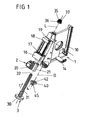
- FIGs 1, 2a and 2b is a driver for a motor vehicle window regulator shown, the a receiving area 1 for a window pane to be adjusted as well a connecting section 2 with a nipple chamber 20 for producing a Has connection with the drive cable of a motor vehicle window lifter.
- the receiving area 1 is formed by a base body 10 of the driver and an associated clamping jaw 11, which counteracts such by means of a clamping screw 12 the base body 10 can be clamped so that one of a disc holder 7 in Area of their lower edge encompassed window pane between the base body 10 and the clamping jaw 11 can be clamped, the clamping screw 12 passes through a pane opening provided for this purpose and the clamping jaw 11 together with the disk holder 7 from one of the base body 10 protruding elastic hook 14 is encompassed.
- Such carriers are general known, so that the details of the disc attachment are not explained here.
- Two bearing sections 16, 18 stand laterally from the base body 10 of the driver each have an opening 17 and 19 for receiving the shaft 31 a Have adjusting screw 3.
- the two bearing sections 16, 18 are along the Longitudinal axis L of the shaft 31 of the adjusting screw 3 spaced apart and thus enable the setting of the connecting section 2 with the nipple chamber 20 along that direction.
- the connecting section 2 is between the two Bearing sections 16, 18 arranged on the shaft 31 of the adjusting screw 3, namely by means of a section 21 provided with an internal thread.
- an external toothing Actuating section 30 in the form of a screw head designed as a gear provided, which also with a gear with an external toothing 40th trained drive element 4 is engaged.
- the drive element 4 is a Pin 45 rotatable in another protruding from the base body 10 Bearing section 15 of the driver mounted and has an inner polygon 42, the an actuation of the drive element 4 allows with a suitable tool.
- the axis of rotation D of the drive element 4 runs parallel to the longitudinal axis L of the Adjustment screw 3.
- the maximum possible adjustment of the nipple chamber 20 is due to the distance of the two bearing sections 16, 18 of the base body 10 along the longitudinal axis L of the Set screw 3 limited.
- a lock nut 35 which on the the actuating head 30 facing away from the end 32 of the threaded shaft 31 Adjusting screw 3 is screwable.
- the lock nut 35 can optionally on one Outside polygon 36 or an inner polygon 37 with a suitable tool be operable.
- the direction r along which the longitudinal axis L of the adjusting screw 3 extends and along which the nipple chamber 20 is adjustable by means of the adjusting screw 3 essentially the vertical vehicle axis z (see FIG. 3) or points at least a substantial component in the direction of the vertical vehicle axis z on, so that the arrangement shown in Figures 1, 2a and 2b in particular a Setting the nipple chamber 20 of the driver with respect to the base body 10 of the Driver allowed along the vertical vehicle axis.
- Adjustment screw 3 and the lock nut 35 can each by a from above to the driver guided tool can be operated, which for this purpose with the Inner polygon 42 of the drive element 4 or the outer or inner polygon 36 or 37 of the lock nut 35 is engaged.
- FIG. 3 shows a motor vehicle door consisting of an outer skin A, one Inner door skin I, one on a large section of the inner door skin I attached door module carrier T, on which different functional components of a Motor vehicle door, such as. B. a window regulator, a door lock, a speaker system and a side airbag module can be preassembled, as well as a door interior paneling V.
- a Motor vehicle door such as. B. a window regulator, a door lock, a speaker system and a side airbag module can be preassembled, as well as a door interior paneling V.
- the height of the door is adjustable by means of a conventional cable window lifter Window F on which a driver M of the in Figures 1 to 2b shown type with the drive mechanism (drive cable) of the cable window lifter is connected and through a door shaft S in the vicinity of it Undershot U in the area between the outer skin A and the inner skin I is led. There, the window pane F is received by the driver M.
- the window lifter shown in FIG. 3 can in particular be a Act so-called double-stranded window lifter, which by means of a drive cable Form of a closed rope loop two along the vehicle's longitudinal axis (vertical to the yz plane shown in FIG. 3) drives drivers spaced apart from one another, each a section of the window pane in the area of the lower edge of the pane embrace and absorb.
- Figure 3 of these two along the Vehicle longitudinal axis that is arranged one behind the other perpendicular to the image plane Only the front driver M can be seen.
- the B-pillar-side driver M that is the driver located adjacent to the B-pillar of the vehicle, during the other driver located further ahead, adjacent to the A-pillar, is hidden.
- a double-strand cable window lifter only one of the two drivers, in this case the one on the B-pillar side that can be seen in FIG Driver M, with an adjustment mechanism of the in Figures 1, 2a and 2b shown type, while the other driver is only passive understand the respective setting of the window pane, in such a way that the lower edge of the pane is defined along the horizontal (Vehicle longitudinal direction) runs.
- the door shaft S is delimited on the side of the outer door skin A by a Shaft reinforcement SV and on the side of the inner door skin I through a door parapet B, on which the inner door panel V is attached.
- the door shaft S thus forms in the upper area of the formed by the outer door skin A and the inner door skin I.
- Door body an opening through which the window pane F from above led in sections into the area between outer door skin A and inner door skin I. can be.
- window pane F by means of the associated, not shown in Figure 3 Window lifter lowered into its lowest pane position, so there is almost that entire window pane in the area between outer door skin A and inner door skin I; only the upper pane edge O then still protrudes through the door shaft S. upwards.
- the window pane F is by means of the window lifter move to its uppermost position, it protrudes almost completely from the door shaft S out; only that part of the window pane F which is accommodated in the driver
- the area around the lower edge U is still in the area between Outer door skin A and inner door skin I.
- the window pane F In the uppermost pane position, which can be reached using the window regulator can, it must be ensured that the window pane F with its upper edge O completely included in a section of the window seal provided for this purpose is. This is the only way to ensure that the window pane is in its upper pane position moisture and watertight sealing of the vehicle interior to the outside out.
- the driver M according to FIGS. 2a and 2b provided that the connecting section 2 over which the driver is connected to the drive mechanism (drive cable) of the window lifter, along the vertical vehicle axis z relative to the receiving area 1 of the driver M. can move, which serves to accommodate the window pane F to be adjusted.
- the adjusting screw 3, the drive element 4 and the lock nut 35 are in Figure 3 in Area of the driver M each shown schematically and with the reference symbol E. (for the adjusting screw), G (for the drive element) and K (for the lock nut) Mistake.
- both the drive element G and the Lock nut K can each be operated by means of a tool W that above along the vertical vehicle axis z through the door shaft S to the corresponding element G or K is guided and engaged with it.
- door shaft S must have such a width in the area of the door sill B that the tool W next to the window pane F through the shaft S in the area between outer door skin A and inner door skin I can be performed.
- Figure 3 shows an assembly step in which a tool W from above through the Door shaft S protrudes into the area between outer door skin A and inner door skin I. and with an inner polygon grips the outer polygon of the counter nut K to this to operate, that is, a position of the previously set by means of the adjusting screw E. Fix nipple chamber 20 (see Figures 1 to 2b).
- a suitable tool W (preferably under Use the same tool W as for the lock nut K) das Actuate drive element G to rotate the drive element G to trigger coupled adjusting screw E, which in turn leads to readjustment of the Position of the nipple chamber 20 (see Figures 1 to 2b) with respect to the base body 10 of the driver leads.
- the arrangement shown in Figure 3 has the significant advantage that both the Actuation of the adjusting screw E serving drive element G as well as for Fixing the adjusting screw in a specific position lock nut K in each case from above through the door shaft S, that is along the same direction from a tool W can be grasped and that this is with the window pane F raised can be done so that it can be immediately determined whether the current position of the Nipple chamber to the desired position of the upper pane edge O in the assigned Section of the washer seal leads.
- the tool W for actuating the Adjusting screw E is not located on the opposite of lock nut K Actuating section 30 (see Figures 1 to 2b) of the adjusting screw. Because this could not be grasped from above using a tool, since the Lock nut K and the shaft of the adjusting screw E give access to the Block the operating section from above. Instead, the Adjusting screw E via the separate drive element G, which is vertical in one plane to the vertical vehicle axis z or to the longitudinal axis of the adjusting screw E next to the Actuating section of the adjusting screw E is arranged and its axis of rotation runs outside (next to) the longitudinal axis of the adjusting screw E. This can Tool W for gripping the drive element G on the threaded shaft of the Adjustment screw E is passed and extends next to this if it is Grips drive element G for actuating the adjusting screw E.
Landscapes
- Window Of Vehicle (AREA)
- Power-Operated Mechanisms For Wings (AREA)
Abstract
Description
- Fig. 1
- eine Explosionsdarstellung eines Mitnehmers mit einem Grundkörper und einer an dem Grundkörper angeordneten, mittels einer Einstellschraube in ihrer Position verstellbaren Nippelkammer;
- Fig. 2a und 2b
- zwei perspektivische Darstellungen des Mitnehmers aus Figur 1, wobei zusätzlich an dem Grundkörper vorgesehene Klemmbacken zur Aufnahme einer zu verstellenden Fensterscheibe dargestellt sind;
- Fig. 3
- eine schematische Darstellung eines Mitnehmers gemäß den Figuren 1, 2a und 2b nach dem Einbau in eine Kraftfahrzeugtür.
Claims (21)
- Mitnehmer für einen Kraftfahrzeugfensterheber mitdadurch gekennzeichnet, dass der Betätigungsabschnitt (30) als Getriebeelement ausgebildet ist, welches derart mit einem Antriebselement (4) gekoppelt ist, dass das Einstellelement (3) zur Einstellung der Lage des Verbindungsabschnittes (2) relativ zu dem Aufnahmebereich (1) durch Einwirkung auf das Antriebselement (4) betätigbar ist.einem Aufnahmebereich zur Aufnahme einer mittels des Fensterhebers verstellbaren Fensterscheibe,einem Verbindungsabschnitt zur Verbindung des Mitnehmers mit einer Antriebseinrichtung des Fensterhebers, dessen Lage relativ zu dem Aufnahmebereich einstellbar ist, undeinem Einstellelement mit einem Betätigungsabschnitt, das zur Einstellung der Lage des Verbindungsabschnittes relativ zu dem Aufnahmebereich betätigbar ist,
- Mitnehmer nach Anspruch 1, dadurch gekennzeichnet, dass das Einstellelement (3) einen Einstellabschnitt (31) aufweist, der von dem Betätigungsabschnitt (30) absteht und der bei einer Betätigung des Einstellelementes (3) die Einstellung der Lage des Verbindungsabschnittes (2) bewirkt.
- Mitnehmer nach Anspruch 1 oder 2, dadurch gekennzeichnet, dass das Antriebselement (4) zur Betätigung mittels eines Werkzeugs (W) ausgebildet ist.
- Mitnehmer nach Anspruch 2 und 3, dadurch gekennzeichnet, dass das Werkzeug (W) entlang einer Richtung mit dem Antriebselement (4) in Eingriff bringbar ist, die im Wesentlichen entgegengesetzt zu der Richtung (r) verläuft, entlang der der Einstellabschnitt (31) von dem Betätigungsabschnitt (30) absteht.
- Mitnehmer nach einem der Ansprüche 2 bis 4, dadurch gekennzeichnet, dass das Antriebselement (4) in einer Ebene neben dem Betätigungsabschnitt (30) angeordnet ist, die sich im Wesentlichen senkrecht zu der Richtung (r) erstreckt, entlang der der Einstellabschnitt (31) von dem Betätigungsabschnitt (30) absteht.
- Mitnehmer nach einem der vorhergehenden Ansprüche, dadurch gekennzeichnet, dass das Einstellelement (3) längserstreckt ausgebildet ist.
- Mitnehmer nach einem der Ansprüche 3 bis 5 und Anspruch 6, dadurch gekennzeichnet, dass das Werkzeug (W) sich im Wesentlichen neben dem Einstellabschnitt (31) erstreckt, wenn es mit dem Antriebselement (4) in Eingriff steht.
- Mitnehmer nach einem der vorhergehenden Ansprüche, dadurch gekennzeichnet, dass das Einstellelement (3) als Einstellschraube ausgebildet ist.
- Mitnehmer nach einem der vorhergehenden Ansprüche, dadurch gekennzeichnet, dass ein zusätzliches Fixierelement (35) zur Fixierung einer zuvor gewählten Einstellung des Einstellelementes (3) vorgesehen ist.
- Mitnehmer nach Anspruch 8 und 9, dadurch gekennzeichnet, dass das Fixierelement (35) als Kontermutter ausgebildet ist.
- Mitnehmer nach Anspruch 9 oder 10, dadurch gekennzeichnet, dass das Antriebselement (4) und das zusätzliche Fixierelement (35) entlang derselben Richtung mit einem Werkzeug (W) in Eingriff bringbar sind.
- Mitnehmer nach einem der vorhergehenden Ansprüche, dadurch gekennzeichnet, dass das Antriebselement (4) - bezogen auf den in eine Kraftfahrzeugtür eingebauten Zustand des Mitnehmers - von oben her entlang der vertikalen Fahrzeugachse (z) mit einem Werkzeug (W) in Eingriff bringbar ist, das auf das Antriebselement (4) einwirkt.
- Mitnehmer nach Anspruch 12, dadurch gekennzeichnet, dass das Werkzeug (W) durch den Türschacht (S) hindurch mit dem Antriebselement (4) in Eingriff bringbar ist, durch den die Fensterscheibe (F) aus dem Türkörper (A, I) hinausragt.
- Mitnehmer nach einem der vorhergehenden Ansprüche, dadurch gekennzeichnet, dass sich die Lage des Verbindungsabschnittes (2) relativ zu dem Aufnahmebereich (1 ) des Mitnehmers, bezogen auf den in eine Fahrzeugtür eingebauten Zustand des Mitnehmers, entlang der vertikalen Fahrzeugachse (z) verstellen lässt.
- Kraftfahrzeugtür nach einem der vorhergehenden Ansprüche, dadurch gekennzeichnet, dass der Betätigungsabschnitt (30) und das Antriebselement (4) über Verzahnungsbereiche miteinander in Eingriff stehen.
- Mitnehmer nach einem der vorhergehenden Ansprüche, dadurch gekennzeichnet, dass der Verbindungsabschnitt (2) verschieblich an einem Grundkörper (10) des Aufnahmebereiches (1) gelagert ist und dass das Einstellelement (3) auf den Verbindungsabschnitt (2) zur Einstellung von dessen Lage einwirkt.
- Mitnehmer nach einem der vorhergehenden Ansprüche, dadurch gekennzeichnet, dass der Verbindungsabschnitt (2) längsverschieblich auf dem Einstellelement (3) lagert.
- Mitnehmer nach einem der vorhergehenden Ansprüche, dadurch gekennzeichnet, dass das Einstellelement (3) und/oder das Antriebselement (4) an einem Grundkörper (10) des Mitnehmers gelagert sind.
- Mitnehmer nach einem der vorhergehenden Ansprüche, dadurch gekennzeichnet, dass der Verbindungsabschnitt (2) eine Nippelkammer (20) zur Verbindung des Mitnehmers mit einem Zugmittel der Antriebseinrichtung des Fensterhebers aufweist.
- Kraftfahrzeugtür mit einem Fensterheber zum Anheben und Absenken einer Fensterscheibe und einem Mitnehmer nach einem der vorhergehenden Ansprüche.
- Kraftfahrzeugtür nach Anspruch 20, dadurch gekennzeichnet, dass der Türkörper (A, I) der Kraftfahrzeugtür einen Türschacht (S) bildet, durch den hindurch von oben her ein Werkzeug (W) mit dem Antriebselement (4) in Eingriff bringbar ist.
Applications Claiming Priority (4)
| Application Number | Priority Date | Filing Date | Title |
|---|---|---|---|
| DE20214668U DE20214668U1 (de) | 2002-09-18 | 2002-09-18 | Mitnehmer für einen Kraftfahrzeugfensterheber |
| DE20214668U | 2002-09-18 | ||
| DE10331003 | 2003-07-03 | ||
| DE10331003A DE10331003A1 (de) | 2002-09-18 | 2003-07-03 | Mitnehmer für einen Kraftfahrzeugfensterheber |
Publications (3)
| Publication Number | Publication Date |
|---|---|
| EP1400650A2 true EP1400650A2 (de) | 2004-03-24 |
| EP1400650A3 EP1400650A3 (de) | 2009-04-22 |
| EP1400650B1 EP1400650B1 (de) | 2011-05-25 |
Family
ID=31947648
Family Applications (1)
| Application Number | Title | Priority Date | Filing Date |
|---|---|---|---|
| EP20030090290 Expired - Lifetime EP1400650B1 (de) | 2002-09-18 | 2003-09-09 | Mitnehmer für einen Kraftfahrzeugfensterheber |
Country Status (1)
| Country | Link |
|---|---|
| EP (1) | EP1400650B1 (de) |
Cited By (6)
| Publication number | Priority date | Publication date | Assignee | Title |
|---|---|---|---|---|
| FR2895765A1 (fr) * | 2006-01-05 | 2007-07-06 | Arvinmeritor Light Vehicle Sys | Curseur de leve-vitre et procede d'assemblage d'un ensemble comprenant ce curseur avec une vitre |
| EP1914371A1 (de) | 2006-10-18 | 2008-04-23 | Melchor Daumal Castellon | Vorrichtung zur Einstellung von Fensterhebern |
| KR100839659B1 (ko) | 2007-08-30 | 2008-06-19 | 주식회사 광진엔지니어링 | 자동차용 윈도우 레귤레이터의 클램핑장치 |
| CN116575831A (zh) * | 2022-02-09 | 2023-08-11 | 麦格纳覆盖件有限公司 | 可调整升降器板组件和窗调节器导轨及相关方法 |
| CN116696179A (zh) * | 2022-03-04 | 2023-09-05 | 恩坦华产品有限公司 | 用于汽车玻璃的可调节游标 |
| US12196025B2 (en) | 2022-02-09 | 2025-01-14 | Magna Closures Inc. | Adjustable lifter plate assembly and window regulator rails for door glass and associated methods |
Family Cites Families (1)
| Publication number | Priority date | Publication date | Assignee | Title |
|---|---|---|---|---|
| DE4102942C1 (en) * | 1991-01-31 | 1991-11-21 | Bayerische Motoren Werke Ag, 8000 Muenchen, De | Car window raising gear - is installed in door and incorporates adjustment by set-screw |
-
2003
- 2003-09-09 EP EP20030090290 patent/EP1400650B1/de not_active Expired - Lifetime
Cited By (9)
| Publication number | Priority date | Publication date | Assignee | Title |
|---|---|---|---|---|
| FR2895765A1 (fr) * | 2006-01-05 | 2007-07-06 | Arvinmeritor Light Vehicle Sys | Curseur de leve-vitre et procede d'assemblage d'un ensemble comprenant ce curseur avec une vitre |
| EP1914371A1 (de) | 2006-10-18 | 2008-04-23 | Melchor Daumal Castellon | Vorrichtung zur Einstellung von Fensterhebern |
| KR100839659B1 (ko) | 2007-08-30 | 2008-06-19 | 주식회사 광진엔지니어링 | 자동차용 윈도우 레귤레이터의 클램핑장치 |
| CN116575831A (zh) * | 2022-02-09 | 2023-08-11 | 麦格纳覆盖件有限公司 | 可调整升降器板组件和窗调节器导轨及相关方法 |
| US12196025B2 (en) | 2022-02-09 | 2025-01-14 | Magna Closures Inc. | Adjustable lifter plate assembly and window regulator rails for door glass and associated methods |
| CN116696179A (zh) * | 2022-03-04 | 2023-09-05 | 恩坦华产品有限公司 | 用于汽车玻璃的可调节游标 |
| US20230279712A1 (en) * | 2022-03-04 | 2023-09-07 | Inteva Products, Llc | Adjustable cursor for glass in a vehicle |
| US12281511B2 (en) * | 2022-03-04 | 2025-04-22 | Inteva Products, Llc | Adjustable cursor for glass in a vehicle |
| US20260103932A1 (en) * | 2022-03-04 | 2026-04-16 | Inteva Products, Llc | Adjustable cursor for glass in a vehicle |
Also Published As
| Publication number | Publication date |
|---|---|
| EP1400650A3 (de) | 2009-04-22 |
| EP1400650B1 (de) | 2011-05-25 |
Similar Documents
| Publication | Publication Date | Title |
|---|---|---|
| DE10331003A1 (de) | Mitnehmer für einen Kraftfahrzeugfensterheber | |
| DE3836511C2 (de) | ||
| EP0395847B1 (de) | Antriebseinrichtung für ein motorisch angetriebenes Klappverdeck | |
| DE102008060407A1 (de) | Fensterheberbaugruppe | |
| DE102006012176A1 (de) | Einstellbarer Fensterheber I | |
| DE102019128241A1 (de) | Türmodul mit rahmenloser glaskonfiguration mit einstellbaren glaslaufkanälen | |
| DE202005017077U1 (de) | Schiebetüranordnung für ein Kraftfahrzeug | |
| DE10041498B4 (de) | Schließeinrichtung für eine Fahrzeugtür | |
| DE19956756C2 (de) | Einstellbarer Mitnehmer für einen Fensterheber einer rahmenlosen Fahrzeugtür | |
| DE2936051C2 (de) | Hebevorrichtung für ein Kraftfahrzeug-Schiebedach | |
| EP2329975B1 (de) | Schiebetüre für ein Fahrzeug | |
| DE69408612T2 (de) | Antriebs- und Arretiervorrichtung für Kraftfahrzeugfenster | |
| EP1400650B1 (de) | Mitnehmer für einen Kraftfahrzeugfensterheber | |
| EP1400649A2 (de) | Mitnehmer für einen Kraftfahrzeugfensterheber | |
| WO2017036845A1 (de) | Fensterheberbaugruppe für ein kraftfahrzeug | |
| DE102005033098B4 (de) | Heckklappe für ein Kraftfahrzeug | |
| DE102005041636B4 (de) | Verstelleinrichtung zur Einstellung eines Kraftfahrzeugteiles | |
| DE202015104588U1 (de) | Fensterheberbaugruppe für ein Kraftfahrzeug | |
| DE102007014098A1 (de) | Bahngesteuerter Kraftfahrzeug-Fensterheber | |
| DE202011051890U1 (de) | Fensterheber für Kraftfahrzeuge | |
| DE19513249C1 (de) | Kraftfahrzeug-Türgriff | |
| DE4328494C2 (de) | Schloß für ein Kraftfahrzeug | |
| DE102005044326A1 (de) | Klappenanordnung eines Kraftfahrzeugs | |
| DE102008045905A1 (de) | Kraftfahrzeug mit Spindelantrieb zum Bewegen einer Klappe | |
| DE19856460B4 (de) | Vorrichtung und Verfahren zum Anheben und Absenken einer Fensterscheibe in einer Kraftfahrzeugtür |
Legal Events
| Date | Code | Title | Description |
|---|---|---|---|
| PUAI | Public reference made under article 153(3) epc to a published international application that has entered the european phase |
Free format text: ORIGINAL CODE: 0009012 |
|
| AK | Designated contracting states |
Kind code of ref document: A2 Designated state(s): AT BE BG CH CY CZ DE DK EE ES FI FR GB GR HU IE IT LI LU MC NL PT RO SE SI SK TR |
|
| AX | Request for extension of the european patent |
Extension state: AL LT LV MK |
|
| RIN1 | Information on inventor provided before grant (corrected) |
Inventor name: WICH, HEIKO Inventor name: STAHN, ARMIN |
|
| PUAL | Search report despatched |
Free format text: ORIGINAL CODE: 0009013 |
|
| AK | Designated contracting states |
Kind code of ref document: A3 Designated state(s): AT BE BG CH CY CZ DE DK EE ES FI FR GB GR HU IE IT LI LU MC NL PT RO SE SI SK TR |
|
| AX | Request for extension of the european patent |
Extension state: AL LT LV MK |
|
| RIC1 | Information provided on ipc code assigned before grant |
Ipc: E05F 11/48 20060101ALI20090319BHEP Ipc: E05F 11/38 20060101AFI20040113BHEP |
|
| 17P | Request for examination filed |
Effective date: 20091022 |
|
| AKX | Designation fees paid |
Designated state(s): DE FR GB IT |
|
| GRAP | Despatch of communication of intention to grant a patent |
Free format text: ORIGINAL CODE: EPIDOSNIGR1 |
|
| GRAS | Grant fee paid |
Free format text: ORIGINAL CODE: EPIDOSNIGR3 |
|
| GRAA | (expected) grant |
Free format text: ORIGINAL CODE: 0009210 |
|
| AK | Designated contracting states |
Kind code of ref document: B1 Designated state(s): DE FR GB IT |
|
| REG | Reference to a national code |
Ref country code: GB Ref legal event code: FG4D Free format text: NOT ENGLISH |
|
| REG | Reference to a national code |
Ref country code: DE Ref legal event code: R096 Ref document number: 50313710 Country of ref document: DE Effective date: 20110707 |
|
| PLBE | No opposition filed within time limit |
Free format text: ORIGINAL CODE: 0009261 |
|
| STAA | Information on the status of an ep patent application or granted ep patent |
Free format text: STATUS: NO OPPOSITION FILED WITHIN TIME LIMIT |
|
| 26N | No opposition filed |
Effective date: 20120228 |
|
| PG25 | Lapsed in a contracting state [announced via postgrant information from national office to epo] |
Ref country code: IT Free format text: LAPSE BECAUSE OF FAILURE TO SUBMIT A TRANSLATION OF THE DESCRIPTION OR TO PAY THE FEE WITHIN THE PRESCRIBED TIME-LIMIT Effective date: 20110525 |
|
| REG | Reference to a national code |
Ref country code: DE Ref legal event code: R097 Ref document number: 50313710 Country of ref document: DE Effective date: 20120228 |
|
| PGFP | Annual fee paid to national office [announced via postgrant information from national office to epo] |
Ref country code: DE Payment date: 20140930 Year of fee payment: 12 |
|
| PGFP | Annual fee paid to national office [announced via postgrant information from national office to epo] |
Ref country code: GB Payment date: 20140903 Year of fee payment: 12 |
|
| PGFP | Annual fee paid to national office [announced via postgrant information from national office to epo] |
Ref country code: FR Payment date: 20140906 Year of fee payment: 12 |
|
| REG | Reference to a national code |
Ref country code: DE Ref legal event code: R119 Ref document number: 50313710 Country of ref document: DE |
|
| GBPC | Gb: european patent ceased through non-payment of renewal fee |
Effective date: 20150909 |
|
| REG | Reference to a national code |
Ref country code: FR Ref legal event code: ST Effective date: 20160531 |
|
| PG25 | Lapsed in a contracting state [announced via postgrant information from national office to epo] |
Ref country code: GB Free format text: LAPSE BECAUSE OF NON-PAYMENT OF DUE FEES Effective date: 20150909 Ref country code: DE Free format text: LAPSE BECAUSE OF NON-PAYMENT OF DUE FEES Effective date: 20160401 |
|
| PG25 | Lapsed in a contracting state [announced via postgrant information from national office to epo] |
Ref country code: FR Free format text: LAPSE BECAUSE OF NON-PAYMENT OF DUE FEES Effective date: 20150930 |