EP1400390A2 - Antriebskraftverteilungs- Steuerungsgerät für ein vierradgetriebenes Fahrzeug - Google Patents
Antriebskraftverteilungs- Steuerungsgerät für ein vierradgetriebenes Fahrzeug Download PDFInfo
- Publication number
- EP1400390A2 EP1400390A2 EP03020530A EP03020530A EP1400390A2 EP 1400390 A2 EP1400390 A2 EP 1400390A2 EP 03020530 A EP03020530 A EP 03020530A EP 03020530 A EP03020530 A EP 03020530A EP 1400390 A2 EP1400390 A2 EP 1400390A2
- Authority
- EP
- European Patent Office
- Prior art keywords
- torque
- vehicle
- power distribution
- control
- transfer
- Prior art date
- Legal status (The legal status is an assumption and is not a legal conclusion. Google has not performed a legal analysis and makes no representation as to the accuracy of the status listed.)
- Withdrawn
Links
- 230000006399 behavior Effects 0.000 claims description 43
- 230000005540 biological transmission Effects 0.000 claims description 22
- 230000001965 increasing effect Effects 0.000 abstract description 5
- 230000003247 decreasing effect Effects 0.000 abstract description 3
- 239000012530 fluid Substances 0.000 description 3
- 230000002829 reductive effect Effects 0.000 description 3
- 230000001133 acceleration Effects 0.000 description 2
- 238000010276 construction Methods 0.000 description 1
- 238000010586 diagram Methods 0.000 description 1
- 230000000694 effects Effects 0.000 description 1
- 238000005516 engineering process Methods 0.000 description 1
- 230000002708 enhancing effect Effects 0.000 description 1
- 230000002401 inhibitory effect Effects 0.000 description 1
- 230000004044 response Effects 0.000 description 1
- 230000000717 retained effect Effects 0.000 description 1
Images


Classifications
-
- B—PERFORMING OPERATIONS; TRANSPORTING
- B60—VEHICLES IN GENERAL
- B60W—CONJOINT CONTROL OF VEHICLE SUB-UNITS OF DIFFERENT TYPE OR DIFFERENT FUNCTION; CONTROL SYSTEMS SPECIALLY ADAPTED FOR HYBRID VEHICLES; ROAD VEHICLE DRIVE CONTROL SYSTEMS FOR PURPOSES NOT RELATED TO THE CONTROL OF A PARTICULAR SUB-UNIT
- B60W30/00—Purposes of road vehicle drive control systems not related to the control of a particular sub-unit, e.g. of systems using conjoint control of vehicle sub-units
- B60W30/02—Control of vehicle driving stability
-
- B—PERFORMING OPERATIONS; TRANSPORTING
- B60—VEHICLES IN GENERAL
- B60K—ARRANGEMENT OR MOUNTING OF PROPULSION UNITS OR OF TRANSMISSIONS IN VEHICLES; ARRANGEMENT OR MOUNTING OF PLURAL DIVERSE PRIME-MOVERS IN VEHICLES; AUXILIARY DRIVES FOR VEHICLES; INSTRUMENTATION OR DASHBOARDS FOR VEHICLES; ARRANGEMENTS IN CONNECTION WITH COOLING, AIR INTAKE, GAS EXHAUST OR FUEL SUPPLY OF PROPULSION UNITS IN VEHICLES
- B60K23/00—Arrangement or mounting of control devices for vehicle transmissions, or parts thereof, not otherwise provided for
- B60K23/08—Arrangement or mounting of control devices for vehicle transmissions, or parts thereof, not otherwise provided for for changing number of driven wheels, for switching from driving one axle to driving two or more axles
- B60K23/0808—Arrangement or mounting of control devices for vehicle transmissions, or parts thereof, not otherwise provided for for changing number of driven wheels, for switching from driving one axle to driving two or more axles for varying torque distribution between driven axles, e.g. by transfer clutch
-
- B—PERFORMING OPERATIONS; TRANSPORTING
- B60—VEHICLES IN GENERAL
- B60K—ARRANGEMENT OR MOUNTING OF PROPULSION UNITS OR OF TRANSMISSIONS IN VEHICLES; ARRANGEMENT OR MOUNTING OF PLURAL DIVERSE PRIME-MOVERS IN VEHICLES; AUXILIARY DRIVES FOR VEHICLES; INSTRUMENTATION OR DASHBOARDS FOR VEHICLES; ARRANGEMENTS IN CONNECTION WITH COOLING, AIR INTAKE, GAS EXHAUST OR FUEL SUPPLY OF PROPULSION UNITS IN VEHICLES
- B60K17/00—Arrangement or mounting of transmissions in vehicles
- B60K17/34—Arrangement or mounting of transmissions in vehicles for driving both front and rear wheels, e.g. four wheel drive vehicles
- B60K17/348—Arrangement or mounting of transmissions in vehicles for driving both front and rear wheels, e.g. four wheel drive vehicles having differential means for driving one set of wheels, e.g. the front, at one speed and the other set, e.g. the rear, at a different speed
- B60K17/35—Arrangement or mounting of transmissions in vehicles for driving both front and rear wheels, e.g. four wheel drive vehicles having differential means for driving one set of wheels, e.g. the front, at one speed and the other set, e.g. the rear, at a different speed including arrangements for suppressing or influencing the power transfer, e.g. viscous clutches
Definitions
- the present invention relates to a power distribution control apparatus for a four wheel drive vehicle and more particularly to a power distribution control apparatus having miscellaneous control apparatuses for controlling behaviors of the vehicle by means of a traction control, a braking force control and the like.
- the VDC Vehicle Dynamics Control System
- TCS Traffic Control System
- ABS Antilock Brake System
- ABS Vehicle behavior control apparatus for controlling a wheel slippage ratio within a target value in order to prevent skidding at braking.
- the torque transfer of the power distribution control apparatus is cut off or is controlled so as to reduced to a specified minimum value.
- JP-A-61-37541 discloses a technology in which, when slip controls operate, the four wheel drive is forcedly changed over to the two wheel drive.
- the vehicle behavior control apparatuses when the torque transfer is cut off or restricted to the specified minimum value at the operation of the vehicle behavior control apparatuses, sometimes the vehicle behavior has an inadequate convergence, for example, when excessive torque is generated by a driver's sudden depression of the accelerator pedal at starting on snowy roads, the TCS can not control such excessive torque and as a result the excessive torque is transmitted to either front wheels or rear wheels and the vehicle behavior control has a poor convergence.
- a power distribution control apparatus of a four wheel drive vehicle for controlling a power distribution ratio between front and rear wheels, said apparatus having a transfer having at least one vehicle behavior control means for controlling behaviors of said vehicle,comprisesfriction clutch means, power distribution control means for changing the power distribution ratio by varying a torque transmission capacity of the friction clutch means and torque transmission capacity control means for controlling the torque transmission capacity so as to come into a preestablished region for avoiding a control interference with the vehicle behavior control means and further controlling the torque transmission capacity so as to become larger with an increase of input torque of the transfer.
- the torque transmission capacity control means correct the torque transmission capacity so as to increase power to be distributed to the front wheels when the vehicle is in an oversteer tendency and so as to increase power to be distributed to the rear wheels when the vehicle is in an understeer tendency.
- reference numeral 1 denotes an engine disposed in a front part of a vehicle, from which driving force is transmitted to a transfer 3 through an automatic transmission (including a torque converter) 2 and a transmission output shaft 2a.
- the driving force transmitted to the transfer 3 inputs to a rear final reduction gear unit 7 through a rear drive shaft 4, a propeller shaft 5 and a rear drive pinion shaft 6 and on the other hand the driving force inputs to a front final reduction gear unit 11 through a reduction drive gear 8, a reduction driven gear 9 and a front drive shaft (front drive pinion shaft) 10.
- the automatic transmission 2, the transfer 3 and the front wheel final reduction gear unit 11 are integrally accommodated in a housing 12.
- the driving force inputted to the rear final reduction gear unit 7 is transmitted to a rear left wheel 14rl and a rear right wheel 14rr through a rear left drive axle 13rl and a rear right drive axle 13rr, respectively.
- the driving force inputted to the front final reduction gear unit 11 is transmitted to a front left wheel 14fl and a front right wheel 14fr through a front left drive axle 13fl and a front right drive axle 13fr, respectively.
- the transfer 3 is constituted by a wet multiple disc clutch (transfer clutch) 15 and a transfer piston 16 for changing engagement force (transfer clutch torque) of the transfer clutch 15 to variably control a torque transmission capacity thereof.
- the transfer clutch 15 comprises a clutch drum fixed to the rear drive shaft 4, a plurality of axially spaced drive plates 15a fixed to the clutch drum, and a plurality of axially spaced driven plates 15b disposed in an interleaving relation to the drive plates 15a and mounted on a clutch hub fixed to a reduction drive gear in an axially displaceable manner. Accordingly, the vehicle incorporating the transfer 3 forms a four wheel drive vehicle capable of changing torque distribution ratios between front and rear wheels within a range from 100:0 to 50:50 by controlling transfer clutch torque of the transfer clutch 15.
- the pressure of the transfer piston 16 is supplied from a transfer clutch driving section 40a having a plurality of solenoid valves and hydraulic circuits. Control signals for driving the transfer clutch driving section 40a is outputted from a front-rear power distribution control section 40.
- vehicle incorporates a VDC (Vehicle Dynamic Control) control section 33, a TCS (Traction Control System) control section 34 and an ABS (Antilock Brake System) control section 35 as known vehicle behavior control means.
- VDC Vehicle Dynamic Control
- TCS Traction Control System
- ABS Antilock Brake System
- the VDC control section 33 performs a brake control or an engine power control as desired based on the comparison of driver's operating conditions (target behavior) calculated from steering angle, brake fluid pressure, engine output and the like with traveling conditions of an own vehicle (actual behavior) calculated from yaw rate, forward and backward acceleration, lateral acceleration, wheel speeds and the like.
- target behavior driver's operating conditions
- actual behavior traveling conditions of an own vehicle
- the TCS control section 34 performs a brake control for individual wheels or an engine power control in order to maintain an optimum driving force and an appropriate side force when slippage of driving wheels exceeds a threshold value.
- an ABS control section 35 performs a brake fluid pressure control for individual wheels in order to maintain an optimum braking force and an appropriate side force when slippage of braking wheels exceeds a threshold value.
- the front-rear power distribution control section 40 inputs signals indicative of operating conditions from the VDC control section 33, the TCS control section 34 and the ABS control section 35. Further, the front-rear power distribution control section 40 inputs miscellaneous signals such as wheel speeds ⁇ fl, ⁇ fr, ⁇ rl, ⁇ rr, steering wheel rotation angles ⁇ H, yaw rate ⁇ , engine speeds Ne and engine torque Te, gear ratios I (transmission speeds) and estimated road friction coefficients ⁇ e from wheel speed sensors 21fl, 21fr, 21rl, 21rr, a steering wheel rotation angle sensor 22, a yaw rate sensor 23, an engine control section 32, a transmission control section 24 and a road friction coefficient estimating apparatus 25, respectively.
- miscellaneous signals such as wheel speeds ⁇ fl, ⁇ fr, ⁇ rl, ⁇ rr, steering wheel rotation angles ⁇ H, yaw rate ⁇ , engine speeds Ne and engine torque Te, gear ratios I (transmission speeds) and
- the front-rear power distribution control section 40 calculates a torque sensitive torque Tt, a differential sensitive torque Ts and a yaw rate feedback torque Ty based on respective input signals and calculates a transfer clutch torque Ttr from these torque data.
- a preestablished power distribution ratio Ai for each transmission speed of rear wheels is selected and the torque sensitive torque Tt is calculated from the power distribution ratio of the rear wheels and a transfer input torque Ti.
- Tt Ai ⁇ Ti
- the transfer input torque Ti is calculated from engine torque Te, gear ratio I and friction loss Lf of the automatic transmission 2 as follows.
- Ti (Te ⁇ I) - Lf
- the friction loss Lf is obtained by reference to a table showing the relationship between engine torque and friction losses parameterizing transmission gear ratios (refer to Fig. 3).
- the relationship between engine torque and friction loss is obtained by experiments beforehand.
- the differential sensitive torque Ts is calculated from the respective wheel speeds ⁇ fl, ⁇ fr, ⁇ rl , ⁇ rr, steering wheel rotation angle ⁇ H and transfer input torque Ti.
- Ts KTi ⁇ ( ⁇ N - ⁇ N0)
- ⁇ N0 is a differential mechanically produced by steering angle ⁇ f and vehicle speed V and is calculated from a vehicle model;
- Kti is a proportional factor established by the transfer input torque Ti and is established such that as the transfer input torque Ti is large, the differential is smaller.
- the transfer clutch torque Ttr is calculated as follows using the calculated torque sensitive torque Tt, differential sensitive torque Ts and yaw rate feedback torque Ty.
- Ttr Tt + Ts + Ty
- the front-rear power distribution section 40 has tables for establishing a transfer clutch torque according to a transfer input torque when the VDC control section 33, the TCS control section 34 or the ABS control section 35 operate.
- a region of transfer clutch torque in which an interference with the VDC control can be avoided is established beforehand by experiments or other means.
- the transfer clutch torque Ttr is established to be larger as the transfer input torque becomes large. That is, in case where the transfer input torque Ti is large, the effect of the transfer clutch torque on the VDC control becomes relatively small and therefore the non-interference region is enlarged.
- the VDC control is operative, in order to control the front-rear power distribution ratio in the vicinity of an appropriate distribution ratio for the improvement of convergence of vehicle behavior, it is necessary to establish the transfer clutch torque Ttr to a larger value as the transfer input torque Ti becomes large.
- the table shown in Fig. 4 has been established in view of these situations.
- the established transfer clutch torque Ttr is corrected in an increasing or decreasing direction.
- the transfer clutch torque Ttr is corrected by reference to a table obtained from experiments beforehand.
- the correction amount is established so as to increase with an increase of the absolute value
- the transfer clutch torque Ttr is corrected so as to increase the power distribution on the rear wheel side and when a behavior of oversteer tendency is detected, in order to converge such a behavior, the transfer clutch torque Ttr is corrected so as to increase the power distribution on the front wheel side. It is needless to say that the correction of the transfer clutch torque Ttr is performed so as to come in the non-interference region.
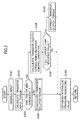
- step S101 necessary signals are read and then the program goes to a step S102 where a friction loss Lf of the automatic transmission at the present gear ratio is obtained from an engine torque Te by referring to a table and a transfer input torque Ti is calculated from the engine torque Te, a gear ratio and the friction loss Lf.
- step S103 it is checked whether or not either of the VDC control section 33, the TCS control section 34 and the ABS control section 35 is operative.
- the program goes to a step S104 where a torque sensitive torque Tt, a differential sensitive torque Ts and a yaw rate feedback torque Ty are calculated respectively and a transfer clutch torque Ttr is calculated based on these torque values.
- the program goes to a step S105 where a hydraulic indicating value corresponding to the calculated transfer clutch torque Ttr is established and the program leaves the routine after the hydraulic indicating value controls the transfer clutch driving section 40a.
- the program goes to a step S106 where the front-rear power distribution control section 40 establishes a transfer clutch torque Ttr in the respective non-interference regions of the vehicle behavior control sections in the table.
- the program goes to a step S107 where it is judged whether or not the absolute value
- step S107 if it is judged that the absolute value
- the program goes to a step S108 where the correction quantity of the transfer clutch torque is established based on
- the transfer clutch torque is increased by that established correction quantity and when the vehicle behavior is in an oversteer tendency, the transfer clutch torque is reduced by that established correction quantity.
- the program goes to a step S105 where an established hydraulic indicating value corresponding to the corrected transfer clutch torque is sent to the transfer clutch control section 40a, leaving the routine.
- the transfer clutch torque Ttr is selected from the region having no interference with other vehicle behavior controls and is established to a larger value as the transfer input torque Ti is large, the transfer 3 according to the embodiment can realize an excellent convergence in vehicle behavior control.
- the convergence in vehicle behavior control can be enhanced by appropriately increasing or decreasing the transfer clutch torque Ttr.
- the power distribution control according to the aforesaid embodiment is exemplified in the four wheel drive vehicle capable of varying the front to rear distribution ratio from 100 : 0 (front drive vehicle) to 50 : 50, however the principle of the present invention is not restricted to such four wheel drive vehicle.
- the present invention may be applied to a four wheel drive vehicle incorporating a planetary gear train designed so as to have an unequal torque distribution ratio between front and rear wheels and having a transfer capable of varying the torque distribution ratio within a range from a specified design value to 50:50.
Landscapes
- Engineering & Computer Science (AREA)
- Transportation (AREA)
- Mechanical Engineering (AREA)
- Chemical & Material Sciences (AREA)
- Combustion & Propulsion (AREA)
- Automation & Control Theory (AREA)
- Arrangement And Driving Of Transmission Devices (AREA)
- Control Of Driving Devices And Active Controlling Of Vehicle (AREA)
- Control Of Vehicle Engines Or Engines For Specific Uses (AREA)
Applications Claiming Priority (2)
| Application Number | Priority Date | Filing Date | Title |
|---|---|---|---|
| JP2002270287A JP2004106649A (ja) | 2002-09-17 | 2002-09-17 | 4輪駆動車の動力配分制御装置 |
| JP2002270287 | 2002-09-17 |
Publications (2)
| Publication Number | Publication Date |
|---|---|
| EP1400390A2 true EP1400390A2 (de) | 2004-03-24 |
| EP1400390A3 EP1400390A3 (de) | 2004-04-28 |
Family
ID=31944527
Family Applications (1)
| Application Number | Title | Priority Date | Filing Date |
|---|---|---|---|
| EP03020530A Withdrawn EP1400390A3 (de) | 2002-09-17 | 2003-09-16 | Antriebskraftverteilungs- Steuerungsgerät für ein vierradgetriebenes Fahrzeug |
Country Status (3)
| Country | Link |
|---|---|
| US (1) | US20040064239A1 (de) |
| EP (1) | EP1400390A3 (de) |
| JP (1) | JP2004106649A (de) |
Cited By (5)
| Publication number | Priority date | Publication date | Assignee | Title |
|---|---|---|---|---|
| EP1686031A3 (de) * | 2005-01-26 | 2007-02-07 | Fuji Jukogyo Kabushiki Kaisha | Steuervorrichtung eines Fahrzeuges mit Allradantrieb |
| WO2007123634A1 (en) * | 2006-03-28 | 2007-11-01 | Borgwarner Inc. | Understeer/oversteer correction for all wheel drive vehicle |
| EP1731347A3 (de) * | 2005-06-10 | 2008-10-29 | Fuji Jukogyo Kabushiki Kaisha | Front- und Heckantriebs- Verteilungssteuerungssystem für ein Fahrzeug |
| EP2022659A1 (de) * | 2007-08-07 | 2009-02-11 | Nissan Motor Co., Ltd. | Verfahren und Vorrichtung zur Steuerung der Antriebskraftverteilung für ein Fahrzeug mit Vierradantrieb |
| EP2338719A1 (de) * | 2009-12-07 | 2011-06-29 | Honda Motor Co., Ltd. | Steuervorrichtung und Fahrzeug mit Allradantrieb |
Families Citing this family (15)
| Publication number | Priority date | Publication date | Assignee | Title |
|---|---|---|---|---|
| SE0402539D0 (sv) * | 2004-10-21 | 2004-10-21 | Haldex Traction Ab | All wheel drive system |
| US7634342B2 (en) * | 2005-03-18 | 2009-12-15 | Honda Motor Co., Ltd. | Method for deploying a torque reduction and torque limitation command through per wheel torque control of a controllable 4-wheel-drive system |
| JP4684755B2 (ja) * | 2005-06-10 | 2011-05-18 | 富士重工業株式会社 | 車両の前後駆動力配分制御装置 |
| JP4684754B2 (ja) * | 2005-06-10 | 2011-05-18 | 富士重工業株式会社 | 車両の前後駆動力配分制御装置 |
| JP2006341825A (ja) * | 2005-06-10 | 2006-12-21 | Fuji Heavy Ind Ltd | 車両の駆動力配分制御装置 |
| JP4730543B2 (ja) * | 2006-03-29 | 2011-07-20 | 三菱自動車工業株式会社 | 車両の駆動力分配制御装置 |
| JP4662060B2 (ja) * | 2006-03-29 | 2011-03-30 | 三菱自動車工業株式会社 | 車両の駆動力分配制御装置 |
| JP4980168B2 (ja) * | 2007-08-01 | 2012-07-18 | 富士重工業株式会社 | 車両挙動制御装置 |
| JP5206229B2 (ja) * | 2008-08-22 | 2013-06-12 | 株式会社ジェイテクト | 前後輪駆動車用の駆動力配分制御装置 |
| US8285465B2 (en) * | 2009-06-30 | 2012-10-09 | Robert Bosch Gmbh | Cooperative traction control system using dual slip controllers |
| US8768595B2 (en) * | 2009-09-03 | 2014-07-01 | Bosch Corporation | Vehicle braking force control device |
| FR2958586B1 (fr) * | 2010-04-12 | 2014-05-09 | Renault Sa | Systeme de commande d'un actionneur de transfert de couple a modes de fonctionnement multiples. |
| US8682556B2 (en) * | 2011-03-30 | 2014-03-25 | Nissin Kogyo Co., Ltd. | Control device for controlling drive force that operates on vehicle |
| US20160144855A1 (en) * | 2013-08-05 | 2016-05-26 | Toyota Jidosha Kabushiki Kaisha | Vibration damping control system for vehicle |
| JP6785317B2 (ja) * | 2016-12-13 | 2020-11-18 | 本田技研工業株式会社 | トルク配分装置の制御装置 |
Citations (1)
| Publication number | Priority date | Publication date | Assignee | Title |
|---|---|---|---|---|
| JPS6137541A (ja) | 1984-07-20 | 1986-02-22 | アルフレツド・テヴエス・ゲーエムベーハー | 全輪駆動型車用スリツプ制御ブレーキシステム |
Family Cites Families (8)
| Publication number | Priority date | Publication date | Assignee | Title |
|---|---|---|---|---|
| JPH01114523A (ja) * | 1987-10-27 | 1989-05-08 | Fuji Heavy Ind Ltd | 4輪駆動車の駆動力制御装置 |
| US5041978A (en) * | 1989-01-17 | 1991-08-20 | Mazda Motor Corporation | Power train control apparatus |
| JPH04151029A (ja) * | 1990-10-11 | 1992-05-25 | Toyoda Mach Works Ltd | 駆動力伝達装置 |
| DE19641101A1 (de) * | 1996-10-04 | 1998-04-09 | Audi Ag | Verfahren zum Steuern der Differentialsperre eines Getriebes |
| DE60035166T2 (de) * | 1999-09-08 | 2008-02-07 | Jtekt Corp., Osaka | Antriebskraftverteilungssystem für ein Kraftfahrzeug mit Allradantrieb |
| JP4456748B2 (ja) * | 2000-10-27 | 2010-04-28 | 富士重工業株式会社 | 4輪駆動車の動力配分制御装置 |
| DE10054023A1 (de) * | 2000-11-01 | 2002-05-08 | Bayerische Motoren Werke Ag | Steuersytem zur variablen Drehmomentverteilung |
| US6688415B2 (en) * | 2002-03-14 | 2004-02-10 | Ford Global Technologies, Llc | Stability control throttle compensation on vehicles with passive all wheel drive systems |
-
2002
- 2002-09-17 JP JP2002270287A patent/JP2004106649A/ja active Pending
-
2003
- 2003-09-16 US US10/662,326 patent/US20040064239A1/en not_active Abandoned
- 2003-09-16 EP EP03020530A patent/EP1400390A3/de not_active Withdrawn
Patent Citations (1)
| Publication number | Priority date | Publication date | Assignee | Title |
|---|---|---|---|---|
| JPS6137541A (ja) | 1984-07-20 | 1986-02-22 | アルフレツド・テヴエス・ゲーエムベーハー | 全輪駆動型車用スリツプ制御ブレーキシステム |
Cited By (11)
| Publication number | Priority date | Publication date | Assignee | Title |
|---|---|---|---|---|
| EP1686031A3 (de) * | 2005-01-26 | 2007-02-07 | Fuji Jukogyo Kabushiki Kaisha | Steuervorrichtung eines Fahrzeuges mit Allradantrieb |
| US7493982B2 (en) | 2005-01-26 | 2009-02-24 | Fuji Jukogyo Kabushiki Kaisha | Control device for a four-wheel drive vehicle |
| EP1731347A3 (de) * | 2005-06-10 | 2008-10-29 | Fuji Jukogyo Kabushiki Kaisha | Front- und Heckantriebs- Verteilungssteuerungssystem für ein Fahrzeug |
| US7610982B2 (en) | 2005-06-10 | 2009-11-03 | Fuji Jukogyo Kabushiki Kaisha | Front and rear drive power distribution control device for vehicle |
| EP2241470A3 (de) * | 2005-06-10 | 2010-12-08 | Fuji Jukogyo Kabushiki Kaisha | Front- und Heckantriebs- Verteilungssteuerungssystem für ein Fahrzeug |
| WO2007123634A1 (en) * | 2006-03-28 | 2007-11-01 | Borgwarner Inc. | Understeer/oversteer correction for all wheel drive vehicle |
| EP2022659A1 (de) * | 2007-08-07 | 2009-02-11 | Nissan Motor Co., Ltd. | Verfahren und Vorrichtung zur Steuerung der Antriebskraftverteilung für ein Fahrzeug mit Vierradantrieb |
| CN101362437B (zh) * | 2007-08-07 | 2012-03-28 | 日产自动车株式会社 | 用于四轮驱动车辆的驱动力分配控制方法和装置 |
| US8374761B2 (en) | 2007-08-07 | 2013-02-12 | Nissan Motor Co., Ltd. | Driving force distribution control method and device for four wheel drive vehicle |
| EP2338719A1 (de) * | 2009-12-07 | 2011-06-29 | Honda Motor Co., Ltd. | Steuervorrichtung und Fahrzeug mit Allradantrieb |
| US8527178B2 (en) | 2009-12-07 | 2013-09-03 | Honda Motor Co., Ltd. | Control apparatus for four-wheel drive vehicle |
Also Published As
| Publication number | Publication date |
|---|---|
| JP2004106649A (ja) | 2004-04-08 |
| US20040064239A1 (en) | 2004-04-01 |
| EP1400390A3 (de) | 2004-04-28 |
Similar Documents
| Publication | Publication Date | Title |
|---|---|---|
| US6634451B2 (en) | Power distribution control system for a vehicle | |
| EP1400390A2 (de) | Antriebskraftverteilungs- Steuerungsgerät für ein vierradgetriebenes Fahrzeug | |
| US6094614A (en) | Driving force distribution control system and road friction coefficient estimating apparatus | |
| EP1538017B1 (de) | Kraftübertragung für ein Fahrzeug mit Allradantrieb | |
| US5701247A (en) | Integrated control system for 4WD vehicles for controlling driving torque distribution | |
| JP3617680B2 (ja) | 4輪駆動車のトラクション制御装置 | |
| EP1232900B1 (de) | Verfahren und Vorrichtung zum Steuern eines Fahrzeugs mit Allradantrieb | |
| US6076033A (en) | Process for controlling yaw moment in vehicle | |
| US8548706B2 (en) | Device operable to control turning of vehicle | |
| US7761215B2 (en) | Device operable to control turning of vehicle using driving and braking force for understeering and oversteering | |
| EP0844129B1 (de) | System zur Kontrolle des Giermomentes in Fahrzeugen | |
| US6587775B2 (en) | Driving force control system for four-wheel drive vehicles | |
| JP3272617B2 (ja) | 車両のヨーモーメント制御装置 | |
| KR20210071133A (ko) | 차량의 자세 제어 방법 | |
| US8204669B2 (en) | Method and device for regulating the driving dynamics of a vehicle | |
| JPH11115719A (ja) | 4輪駆動車の動力配分制御装置 | |
| JP4114065B2 (ja) | 四輪駆動車の挙動制御装置 | |
| EP1522474B1 (de) | Vorrichtung zur Regelung der Fahrzeugbewegung | |
| JP2853474B2 (ja) | 四輪駆動車の駆動力配分装置 | |
| JP4910361B2 (ja) | 車輌の駆動力制御装置 | |
| JP2646764B2 (ja) | 四輪駆動車の駆動力配分制御装置 | |
| JP3518464B2 (ja) | 四輪駆動車の駆動力配分制御装置 | |
| JP4661450B2 (ja) | 車輌の駆動トルク制御装置 | |
| JPH0680035A (ja) | 前後輪と左右輪の駆動力配分総合制御装置 | |
| JP3506223B2 (ja) | 四輪駆動車の駆動力配分制御装置 |
Legal Events
| Date | Code | Title | Description |
|---|---|---|---|
| PUAI | Public reference made under article 153(3) epc to a published international application that has entered the european phase |
Free format text: ORIGINAL CODE: 0009012 |
|
| PUAL | Search report despatched |
Free format text: ORIGINAL CODE: 0009013 |
|
| AK | Designated contracting states |
Kind code of ref document: A2 Designated state(s): AT BE BG CH CY CZ DE DK EE ES FI FR GB GR HU IE IT LI LU MC NL PT RO SE SI SK TR |
|
| AX | Request for extension of the european patent |
Extension state: AL LT LV MK |
|
| AK | Designated contracting states |
Kind code of ref document: A3 Designated state(s): AT BE BG CH CY CZ DE DK EE ES FI FR GB GR HU IE IT LI LU MC NL PT RO SE SI SK TR |
|
| AX | Request for extension of the european patent |
Extension state: AL LT LV MK |
|
| RIC1 | Information provided on ipc code assigned before grant |
Ipc: 7B 60K 17/346 B Ipc: 7B 60K 28/16 B Ipc: 7B 60K 23/08 A |
|
| 17P | Request for examination filed |
Effective date: 20040517 |
|
| AKX | Designation fees paid |
Designated state(s): DE FR GB |
|
| STAA | Information on the status of an ep patent application or granted ep patent |
Free format text: STATUS: THE APPLICATION HAS BEEN WITHDRAWN |
|
| 18W | Application withdrawn |
Effective date: 20051206 |