EP1400335A1 - Anschlussrohrstück, inbesondere Extruderanschlussrohrstück - Google Patents
Anschlussrohrstück, inbesondere Extruderanschlussrohrstück Download PDFInfo
- Publication number
- EP1400335A1 EP1400335A1 EP02020796A EP02020796A EP1400335A1 EP 1400335 A1 EP1400335 A1 EP 1400335A1 EP 02020796 A EP02020796 A EP 02020796A EP 02020796 A EP02020796 A EP 02020796A EP 1400335 A1 EP1400335 A1 EP 1400335A1
- Authority
- EP
- European Patent Office
- Prior art keywords
- connection
- pipe
- complementary
- extruder
- pipe part
- Prior art date
- Legal status (The legal status is an assumption and is not a legal conclusion. Google has not performed a legal analysis and makes no representation as to the accuracy of the status listed.)
- Withdrawn
Links
Images


Classifications
-
- F—MECHANICAL ENGINEERING; LIGHTING; HEATING; WEAPONS; BLASTING
- F16—ENGINEERING ELEMENTS AND UNITS; GENERAL MEASURES FOR PRODUCING AND MAINTAINING EFFECTIVE FUNCTIONING OF MACHINES OR INSTALLATIONS; THERMAL INSULATION IN GENERAL
- F16L—PIPES; JOINTS OR FITTINGS FOR PIPES; SUPPORTS FOR PIPES, CABLES OR PROTECTIVE TUBING; MEANS FOR THERMAL INSULATION IN GENERAL
- F16L27/00—Adjustable joints; Joints allowing movement
- F16L27/08—Adjustable joints; Joints allowing movement allowing adjustment or movement only about the axis of one pipe
- F16L27/0849—Adjustable joints; Joints allowing movement allowing adjustment or movement only about the axis of one pipe the fluid being turned through an angle when passing from one joint element to another
-
- B—PERFORMING OPERATIONS; TRANSPORTING
- B29—WORKING OF PLASTICS; WORKING OF SUBSTANCES IN A PLASTIC STATE IN GENERAL
- B29C—SHAPING OR JOINING OF PLASTICS; SHAPING OF MATERIAL IN A PLASTIC STATE, NOT OTHERWISE PROVIDED FOR; AFTER-TREATMENT OF THE SHAPED PRODUCTS, e.g. REPAIRING
- B29C48/00—Extrusion moulding, i.e. expressing the moulding material through a die or nozzle which imparts the desired form; Apparatus therefor
- B29C48/03—Extrusion moulding, i.e. expressing the moulding material through a die or nozzle which imparts the desired form; Apparatus therefor characterised by the shape of the extruded material at extrusion
- B29C48/07—Flat, e.g. panels
- B29C48/08—Flat, e.g. panels flexible, e.g. films
-
- B—PERFORMING OPERATIONS; TRANSPORTING
- B29—WORKING OF PLASTICS; WORKING OF SUBSTANCES IN A PLASTIC STATE IN GENERAL
- B29C—SHAPING OR JOINING OF PLASTICS; SHAPING OF MATERIAL IN A PLASTIC STATE, NOT OTHERWISE PROVIDED FOR; AFTER-TREATMENT OF THE SHAPED PRODUCTS, e.g. REPAIRING
- B29C48/00—Extrusion moulding, i.e. expressing the moulding material through a die or nozzle which imparts the desired form; Apparatus therefor
- B29C48/25—Component parts, details or accessories; Auxiliary operations
- B29C48/256—Exchangeable extruder parts
- B29C48/2562—Mounting or handling of the die
Definitions
- the invention relates to a connecting pipe piece, in particular Extruder connection pipe piece for the passage of a melt from an extruder to another system component.
- Extruder connection pipe piece for the passage of a melt from an extruder to another system component.
- at the other system components are in particular an adapter to which the one emerging from the extruder Melt is performed.
- the adapter is convenient a wide slot tool downstream.
- On Extruder connection pipe piece must be designed so that the melt is as short as possible to the further system component or led to the adapter can be.
- the invention is the technical problem is based on a connecting pipe piece, in particular extruder connecting pipe piece specify with which all possible Tolerances reliable and above all simple and little can be compensated for in a complex manner.
- the invention teaches a connecting pipe piece, in particular an extruder connecting pipe piece for passing a melt through from an extruder to a further system component, at least one middle pipe part and a first end pipe part connected to a first end of the middle pipe part and a second end pipe part connected to the opposite second end of the middle pipe part are provided, wherein the first end pipe part and the second end pipe part are each connected with a connection surface to a complementary connection surface of the center pipe part, the connection surfaces and the complementary connection surfaces being oriented obliquely to the longitudinal axes of the end pipe parts and to the longitudinal axis of the center pipe part, and wherein each end pipe part and the middle pipe part can be rotated relative to one another about an axis of rotation arranged perpendicular to the respective connection surface and perpendicular to the respectively assigned complementary connection surface.
- Extruder connection pipe piece is also generally means a "connecting pipe piece”.
- Extruder connection pipe piece is also generally means a "connecting pipe piece”.
- Extruder connection pipe piece from three Parts, namely a central tube part, a first and a second tail pipe part. It is within the Invention that the end pipe parts and the middle pipe part are continuously rotatable to each other.
- tailpipe part with its connection surface to the assigned Complementary connection surface of the center tube part placed and the pad is relative to the complement pad rotatable or the complementary connection surface can be rotated relative to the connection surface.
- connection area between Connection area and complementary connection area for the Application is set up sufficiently dense and that insofar as suitable sealing measures are taken or suitable Sealing elements are provided.
- an end pipe part for example the first Tail pipe part is provided for connection to an extruder.
- the other second end pipe part is then expedient connected to an adapter, which is a wide slot tool is connected downstream and the extruder connection pipe piece in this way forms a connecting element in the melt guide area between extruder and Adapter.
- Tail pipe part on the connection surface a circular Internal cross-section and has the central tube part on the assigned complementary pad also one circular inner cross-section. So the melt will expediently in the connection area between the connection surface and complementary pad by one Line section with a circular inner cross section or headed with a cylindrical interior.
- This Embodiment has been in terms of reliable and easy turning of the pipe parts especially proven. This is because they become disadvantageous Avoid elliptical cross-sections in the connection area that inevitably arise when a sloping surface at the forehead a piece of pipe with a circular inner cross section is established.
- connection element Is preferably on an end pipe part with the Connection surface equipped connection element provided, which connecting element has a cylindrical interior has, the cylinder longitudinal axis of this interior is arranged perpendicular to the connection surface.
- Cylindrical interior means an interior circular cross section.
- the middle pipe part Connection element expediently has a connection flange on which the connection surface is provided. It is within the scope of the invention that on the central tube part one equipped with a complementary connection surface Complementary connection element is provided, which Complementary connection element also one has cylindrical interior, the Longitudinal cylinder axis of this interior perpendicular to the Complementary connection surface is arranged. Conveniently, is on both faces or on both Connection sides of the central tube part such a complementary connection element intended.
- the oblique connection surface of a tail pipe part with the Longitudinal axis of this tail pipe part an angle ⁇ of 10 ° to 60 °, preferably from 10 ° to 55 °.
- the angle ⁇ lies preferably between 15 ° and 50 °.
- the angle ⁇ can for example values of 15 °, 30 ° or 45 ° accept.
- the angle ⁇ is preferably in the range between 15 ° and 55 °, preferably between 40 ° and 50 °. It's in the frame of the invention that the assigned to the concerned Connection surface vertical axis of rotation with the longitudinal axis of the relevant end pipe part an angle ⁇ with the forms the aforementioned values.
- a Complementary connection surface of the central tube part with the Longitudinal axis of this central tube part an angle ⁇ of 10 ° forms to 60 °, preferably from 10 ° to 55 °.
- the angle ⁇ is expediently in the range between 15 ° and 50 °.
- the angle ⁇ is preferably in the range between 35 ° and 55 °, preferably between 40 ° and 50 °. It is within the Invention that the above angle ⁇ is the same Has value like the angle ⁇ .
- a linear state of the Extruder connection pipe piece according to the invention can be generated, in which the longitudinal axes of the tailpipe parts and the longitudinal axis of the center tube part are arranged parallel to each other.
- This linear state can be twisted accordingly the end pipe parts or the middle pipe part are generated.
- End pipe parts or middle pipe part can be a first angled condition of the extruder connection pipe piece be produced in which a longitudinal axis of a End raw part perpendicular to the longitudinal axis of the middle pipe part is arranged.
- Tailpipe parts or Middle tube part can expediently a second angled condition of the extruder connection pipe piece be produced in which the longitudinal axes of the two Tail pipe parts parallel to each other and perpendicular to Longitudinal axis of the central tube part are arranged.
- the invention is based on the knowledge that it is in the connection pipe piece according to the invention by a Pipe joint that is simple, flexible and variably adaptable to all possible connection conditions is.
- the connecting pipe piece is particularly suitable as Extruder connection pipe piece in the melt guide area behind an extruder.
- Extruder connection pipe piece can be easily and easily all possible tolerances or all axis and Angular misalignments in the melt guide area compensated become.
- the extruder connection pipe piece can be simple and little complex way quickly to the changed connection situation be adjusted. Nonetheless, it is undisturbed and functionally reliable melt guidance possible.
- the extruder connection pipe piece according to the invention takes measures considerable advantages. It should be emphasized also that the extruder connection pipe piece according to the invention can be produced in a simple and inexpensive manner can and the existing systems with no problem retrofitted such an extruder connection pipe piece can be.
- FIG. 1 shows a system with an extruder 1 Screen changer 2 and an extruder connection pipe section 3, the connects the extruder 1 with an adapter 4.
- the adapter 4 is a wide slot tool 5 in the exemplary embodiment downstream.
- a rigid Extruder connection pipe section 3 provided only by elaborate welding and milling work and can be adapted to the connection conditions.
- Extruder connection pipe section 3 for carrying out a Melt from one extruder 1 to another Plant component.
- a central tube part 6 is provided and one to a first End of the middle tube part 6 connected first Tail pipe part 7 and one on the opposite second End of the middle tube part 6 connected second Tail pipe part 8 provided.
- the first tail pipe part 7 has a first connection surface 9 to a first complementary connection surface 10 of the Middle tube part 6 connected.
- the first pad 9 and the first complementary connection surface 10 are included obliquely to the longitudinal axis 11 of the first tail pipe part 7 and oriented obliquely to the longitudinal axis 12 of the central tube part 6.
- Connection surface 9, 14 or complementary connection surface 10, 15 here and below means on the one hand the one with the Middle pipe part 6 or with the end pipe part 7, 8 in contact standing area as well as in relation to the geometric Relationships, the respective level at which the actually contacting connection surface 9, 14 or complementary connection surface 10, 15 lies.
- the first tail pipe part 7 and the center tube part 6 are perpendicular to the first one Pad 9 and perpendicular to the assigned Complementary connection surface 10 oriented (imaginary) Rotation axis 13 rotatable against each other. That also results from a comparative consideration of FIGS. 2 and 3. According to the first tail pipe part 7 and Center tube part 6 continuously rotatable and thus everyone can between the state in Fig. 2 and the State in Fig. 3 lying intermediate state appropriate twist can be realized.
- the second tail pipe part 8 is with a second Pad 14 to a second complementary pad 15 of the central tube part 6 connected, the second pad 14 and the second complementary pad 15 obliquely to the longitudinal axis 16 of the second Tail pipe part 8 and obliquely to the longitudinal axis 12 of the Center tube part 6 are arranged.
- the second tail pipe part 8 and the center tube part 6 are perpendicular to the second pad 14 and perpendicular to the assigned second complementary connection surface 15 oriented second (imaginary) axis of rotation 17 stepless rotatable against each other.
- An end pipe part 7, 8 can be an extruder 1 or Screen changer 2 must be connected immediately. But it is also possible, the extruder connection pipe piece according to the invention 3 to one already connected to the extruder 1 Connect pipe section.
- Tail pipe part 7, 8 on the connection surface 9, 14 a circular inner cross-section and also has that Middle tube part 6 on the associated complementary connection surface 10, 15 also a circular inner cross section on.
- This circular inner cross section is 4 can be seen in particular.
- the respective Terminal surface 9, 14 having a cylindrical shape Connection element 18 is provided, which is cylindrical Connection element 18 a cylindrical interior having.
- connection element 18 with a connection flange 19 equipped on which the connection surface 9, 14 is provided is.
- this also has in the exemplary embodiment Middle tube part 6 on each side of the respective Complementary connection surface 10, 15 having a cylindrical Complementary connection element 20, which also cylindrical complementary connector 20 a has cylindrical interior.
- the associated Longitudinal cylinder axes, which correspond to the axes of rotation 13, 17, are perpendicular to the complementary connection surfaces 10, 15 arranged.
- the complementary connection element 20 is with a complementary connecting flange 21, on which the respective complementary connection surface 10, 15 is provided is.
- a connection element 8 preferably forms and in Embodiment with the associated Complementary connection element 20 a pipe section, which is cylindrical on the inside or throughout the length of the pipe section has a circular inner cross section. in the Embodiment otherwise corresponds to the first The axis of rotation 13 or the second axis of rotation 17 Central longitudinal axis of the respective cylindrical Pipeline section.
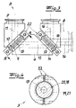
- the embodiment forms the Terminal surface 9, 14 of a tail pipe part 7, 8 or the corresponding level in which the connecting surface 9, 14 lies, with the associated central longitudinal axis 11, 16 this Tail pipe part 7, 8 an angle ⁇ of 45 °. 2 is recognizable that the axis of rotation 13, 17 with the assigned central longitudinal axis 11, 16 of the tail pipe part 7, 8 form an angle ⁇ of 45 °.
- the middle tube part 6 has an angle ⁇ of 45 °. 2 it can also be seen that the axis of rotation 13, 17 with this central longitudinal axis 12 forms an angle ⁇ of 45 °.
- Fig. 3 shows a first angled state of the Extruder connection pipe piece 3, which by turning the first tail pipe part 7 opposite the center pipe part 6 is producible and in which the central longitudinal axis 11 of the first tail pipe part 7 perpendicular to the central longitudinal axis 12 of the Middle tube part 6 and to the central longitudinal axis 16 of the second Tail pipe part 8 is arranged.
- the second tail pipe part 8 was used to represent this first angled state dash-dotted lines.
- connection flange 19 and the complementary connection flange 21 with the help of an annular fixing element 22 are held together.
- the two flanges or their connecting surfaces 9, 14 and complementary connecting surfaces 10, 15 are, as it were, by means of Wedge lock pressed together.
Landscapes
- Engineering & Computer Science (AREA)
- Mechanical Engineering (AREA)
- General Engineering & Computer Science (AREA)
- Extrusion Moulding Of Plastics Or The Like (AREA)
Abstract
Description
wobei zumindest ein Mittelrohrteil sowie ein an ein erstes Ende des Mittelrohrteils angeschlossenes erstes Endrohrteil und ein an dem gegenüberliegenden zweiten Ende des Mittelrohrteils angeschlossenes zweites Endrohrteil vorgesehen ist,
wobei das erste Endrohrteil und das zweite Endrohrteil jeweils mit einer Anschlussfläche an eine Komplementäranschlussfläche des Mittelrohrteils angeschlossen sind, wobei die Anschlussflächen und die Komplementäranschlussflächen schräg zu den Längsachsen der Endrohrteile und zur Längsachse des Mittelrohrteils orientiert sind,
und wobei jedes Endrohrteil und das Mittelrohrteil um eine senkrecht zur jeweiligen Anschlussfläche und senkrecht zur jeweils zugeordneten Komplementäranschlussfläche angeordneten Drehachse gegeneinander verdrehbar sind.
- Fig. 1
- eine Seitenansicht einer Vorrichtung nach dem Stand der Technik,
- Fig. 2
- ein erster Zustand eines erfindungsgemäßen Extruderanschlussrohrstückes,
- Fig. 3
- den Gegenstand nach Fig. 2 in einem zweiten Funktionszustand und
- Fig. 4
- ein Schnitt A-A durch den Gegenstand nach Fig. 3.
Claims (9)
- Anschlussrohrstück, insbesondere Extruderanschlussrohrstück zur Durchleitung einer Schmelze von einem Extruder (1) zu einer weiteren Anlagenkomponente,
wobei zumindest ein Mittelrohrteil (6) sowie ein an ein erstes Ende des Mittelrohrteils (6) angeschlossenes erstes Endrohrteil (7) und ein an dem gegenüberliegenden zweiten Ende des Mittelrohrteils (6) angeschlossenes zweites Endrohrteil (8) vorgesehen ist,
wobei das erste Endrohrteil (7) und das zweite Endrohrteil (8) jeweils mit einer Anschlussfläche (9, 14) an eine Komplementäranschlussfläche (10, 15) des Mittelrohrteils (6) angeschlossen ist, wobei die Anschlussflächen (9, 14) und die Komplementäranschlussflächen (10, 15) schräg zu den Längsachsen (11, 16) der Endrohrteile (7, 8) und zur Längsachse (12) des Mittelrohrteils (6) orientiert sind
und wobei jedes Endrohrteil (7, 8) und das Mittelrohrteil (6) um eine senkrecht zur jeweiligen Anschlussfläche (9, 14) und senkrecht zur jeweils zugeordneten Komplementäranschlussfläche (10, 15) angeordneten Drehachse (13, 17) gegeneinander verdrehbar sind. - Anschlussrohrstück nach Anspruch 1, wobei ein Endrohrteil (7, 8) zum Anschluss an einen Extruder (1) vorgesehen ist.
- Anschlussrohrstück nach einem der Ansprüche 1 oder 2, wobei ein Endrohrteil (7, 8) an der Anschlussfläche (9, 14) einen kreisförmigen Innenquerschnitt aufweist und wobei das Mittelrohrteil (6) an der zugeordneten Komplementäranschlussfläche (10, 15) ebenfalls einen kreisförmigen Innenquerschnitt aufweist.
- Anschlussrohrstück nach einem der Ansprüche 1 bis 3, wobei an einem Endrohrteil (7, 8) ein mit der Anschlussfläche (9, 14) ausgestattetes Anschlusselement (18) vorgesehen ist, welches Anschlusselement (18) einen zylinderförmigen Innenraum aufweist, wobei die Zylinderlängsachse senkrecht zu der Anschlussfläche (9, 14) orientiert ist.
- Anschlussrohrstück nach einem der Ansprüche 1 bis 4, wobei an dem Mittelrohrteil (6) ein mit einer Komplementäranschlussfläche (10, 15) ausgestattetes Komplementäranschlusselement (20) vorgesehen ist, welches Komplementäranschlusselement (20) einen zylinderförmigen Innenraum aufweist, wobei die Zylinderlängsachse dieses Innenraumes senkrecht zu der Komplementäranschlussfläche (10, 15) orientiert ist.
- Anschlussrohrstück nach einem der Ansprüche 1 bis 5, wobei eine Anschlussfläche (9, 14) eines Endrohrteils (7, 8) mit der Längsachse (11, 16) dieses Endrohrteils (7, 8) einen Winkel α von 10° bis 60°, vorzugsweise von 10° bis 55° bildet.
- Anschlussrohrstück nach einem der Ansprüche 1 bis 6, wobei eine Komplementäranschlussfläche (10, 15) des Mittelrohrteils (6) mit der Längsachse (12) des Mittelrohrteils (6) einen Winkel β von 10° bis 60°, vorzugsweise von 10° bis 55° bildet.
- Anschlussrohrstück nach einem der Ansprüche 1 bis 7, wobei ein linearer Zustand des Extruderanschlussrohrstückes (3) erzeugbar ist, in dem die Längsachsen (11, 12, 16) der Endrohrteile (7, 8) und des Mittelrohrteils (6) parallel zueinander angeordnet sind.
- Anschlussrohrstück nach einem der Ansprüche 1 bis 6, wobei durch Verdrehen von Endrohrteilen (7, 8) bzw. Mittelrohrteil (6) ein gewinkelter Zustand des Extruderanschlussrohrstückes (3) herstellbar ist, in dem die Längsachsen (11, 16) der Endrohrteile (7, 8) parallel zueinander und senkrecht zur Längsachse (12) des Mittelrohrteils (6) angeordnet sind.
Priority Applications (2)
| Application Number | Priority Date | Filing Date | Title |
|---|---|---|---|
| EP02020796A EP1400335A1 (de) | 2002-09-17 | 2002-09-17 | Anschlussrohrstück, inbesondere Extruderanschlussrohrstück |
| CNB031220517A CN1318664C (zh) | 2002-09-17 | 2003-04-24 | 连接管件,特别是挤压机连接管件 |
Applications Claiming Priority (1)
| Application Number | Priority Date | Filing Date | Title |
|---|---|---|---|
| EP02020796A EP1400335A1 (de) | 2002-09-17 | 2002-09-17 | Anschlussrohrstück, inbesondere Extruderanschlussrohrstück |
Publications (1)
| Publication Number | Publication Date |
|---|---|
| EP1400335A1 true EP1400335A1 (de) | 2004-03-24 |
Family
ID=31896860
Family Applications (1)
| Application Number | Title | Priority Date | Filing Date |
|---|---|---|---|
| EP02020796A Withdrawn EP1400335A1 (de) | 2002-09-17 | 2002-09-17 | Anschlussrohrstück, inbesondere Extruderanschlussrohrstück |
Country Status (2)
| Country | Link |
|---|---|
| EP (1) | EP1400335A1 (de) |
| CN (1) | CN1318664C (de) |
Families Citing this family (1)
| Publication number | Priority date | Publication date | Assignee | Title |
|---|---|---|---|---|
| CN113187974A (zh) * | 2021-04-25 | 2021-07-30 | 梁永清 | 一种连接管组件 |
Citations (6)
| Publication number | Priority date | Publication date | Assignee | Title |
|---|---|---|---|---|
| DE181327C (de) * | ||||
| DE805469C (de) * | 1950-02-16 | 1951-05-21 | Emil Zepp | Zum Aneinandersetzen im Winkel oder in der Geraden geeignete Rohrstuecke |
| DE1077741B (de) * | 1957-01-24 | 1960-03-17 | Siemens Ag | Flanschverbindung fuer zwei Hohlleiterabschnitte einer Hochfrequenzleitung |
| US3216080A (en) * | 1962-10-12 | 1965-11-09 | Midland Ross Corp | Extrusion apparatus for coating pipe |
| FR1469425A (fr) * | 1966-02-21 | 1967-02-10 | élément de tuyauterie | |
| US3692447A (en) * | 1970-11-30 | 1972-09-19 | Crompton & Knowles Corp | Multiple extrusion apparatus |
-
2002
- 2002-09-17 EP EP02020796A patent/EP1400335A1/de not_active Withdrawn
-
2003
- 2003-04-24 CN CNB031220517A patent/CN1318664C/zh not_active Expired - Fee Related
Patent Citations (6)
| Publication number | Priority date | Publication date | Assignee | Title |
|---|---|---|---|---|
| DE181327C (de) * | ||||
| DE805469C (de) * | 1950-02-16 | 1951-05-21 | Emil Zepp | Zum Aneinandersetzen im Winkel oder in der Geraden geeignete Rohrstuecke |
| DE1077741B (de) * | 1957-01-24 | 1960-03-17 | Siemens Ag | Flanschverbindung fuer zwei Hohlleiterabschnitte einer Hochfrequenzleitung |
| US3216080A (en) * | 1962-10-12 | 1965-11-09 | Midland Ross Corp | Extrusion apparatus for coating pipe |
| FR1469425A (fr) * | 1966-02-21 | 1967-02-10 | élément de tuyauterie | |
| US3692447A (en) * | 1970-11-30 | 1972-09-19 | Crompton & Knowles Corp | Multiple extrusion apparatus |
Also Published As
| Publication number | Publication date |
|---|---|
| CN1318664C (zh) | 2007-05-30 |
| CN1483862A (zh) | 2004-03-24 |
Similar Documents
| Publication | Publication Date | Title |
|---|---|---|
| EP0671985B1 (de) | Presswerkzeug | |
| DE3838935A1 (de) | Kupplungsstueck | |
| DE2927716A1 (de) | Fluid-verbindungsstueck | |
| DE19542463B4 (de) | Rohrkupplung | |
| DE202013012532U1 (de) | Vorrichtung zum Verbinden von zwei exzentrisch zueinander angeordneten Stäben und Einrichtung zum Verbinden von zwei Bauelementen mit jeweils einem Stab | |
| EP0315772A2 (de) | Verbindung eines Kugelgelenkschaftes mit einem Rohr | |
| CH667505A5 (de) | Rohrverbindung zum verbinden von zwei mit gewinden versehenen rohrenden. | |
| CH616733A5 (de) | ||
| EP1400335A1 (de) | Anschlussrohrstück, inbesondere Extruderanschlussrohrstück | |
| DE3937888C2 (de) | ||
| DE69907212T2 (de) | Rohrverbindung | |
| DE2141846A1 (de) | Rohrkupplung | |
| WO1994007072A1 (de) | Lösbare rohrverbindung | |
| DE3536297A1 (de) | Schlauch und kupplung umfassende anordnung sowie schlauchkupplung hierfuer | |
| DE19911814A1 (de) | Flanschverbindung zwischen zwei Rohrstücken | |
| DE202006006746U1 (de) | Verbindungseinheit mit Schelle | |
| DE4317498A1 (de) | Zusammenfassung aufeinander folgender Abschnitte von Hängebahnlaufschienen, dafür vorgesehener Verbinder und Verfahren zur Durchführung der Zusammenfassung | |
| DE2819921A1 (de) | Vorrichtung zum verbinden zweier rohre bzw. zweier rohrstutzen | |
| DE3402583A1 (de) | Rohranschlussvorrichtung | |
| DE10354845B4 (de) | Rohrleitungsbauteil | |
| EP3460306A1 (de) | Rohr mit verbindungsflansch | |
| DE102004009416A1 (de) | Rohrverbindung | |
| DE19957640C2 (de) | Verbindungsvorrichtung | |
| EP2988045B1 (de) | Dichtung für eine hauseinführung, insbesondere mehrspartenhauseinführung | |
| CH664813A5 (en) | Shift prevention for pipe coupling - uses sheet metal half-shells with sharp internal protrusions clamped together |
Legal Events
| Date | Code | Title | Description |
|---|---|---|---|
| PUAI | Public reference made under article 153(3) epc to a published international application that has entered the european phase |
Free format text: ORIGINAL CODE: 0009012 |
|
| AK | Designated contracting states |
Kind code of ref document: A1 Designated state(s): AT BE BG CH CY CZ DE DK EE ES FI FR GB GR IE IT LI LU MC NL PT SE SK TR |
|
| AX | Request for extension of the european patent |
Extension state: AL LT LV MK RO SI |
|
| 17P | Request for examination filed |
Effective date: 20040302 |
|
| AKX | Designation fees paid |
Designated state(s): AT BE BG CH CY CZ DE DK EE ES FI FR GB GR IE IT LI LU MC NL PT SE SK TR |
|
| AXX | Extension fees paid |
Extension state: SI Payment date: 20040421 Extension state: MK Payment date: 20040421 |
|
| RTI1 | Title (correction) |
Free format text: CONNECTING PIPE SECTION FOR AN EXTRUDER |
|
| GRAP | Despatch of communication of intention to grant a patent |
Free format text: ORIGINAL CODE: EPIDOSNIGR1 |
|
| RAP1 | Party data changed (applicant data changed or rights of an application transferred) |
Owner name: REIFENHAEUSER GMBH & CO. KG MASCHINENFABRIK |
|
| STAA | Information on the status of an ep patent application or granted ep patent |
Free format text: STATUS: THE APPLICATION IS DEEMED TO BE WITHDRAWN |
|
| 18D | Application deemed to be withdrawn |
Effective date: 20070718 |