EP0671985B1 - Presswerkzeug - Google Patents
Presswerkzeug Download PDFInfo
- Publication number
- EP0671985B1 EP0671985B1 EP94901870A EP94901870A EP0671985B1 EP 0671985 B1 EP0671985 B1 EP 0671985B1 EP 94901870 A EP94901870 A EP 94901870A EP 94901870 A EP94901870 A EP 94901870A EP 0671985 B1 EP0671985 B1 EP 0671985B1
- Authority
- EP
- European Patent Office
- Prior art keywords
- press
- pressing
- jaws
- ring
- groove
- Prior art date
- Legal status (The legal status is an assumption and is not a legal conclusion. Google has not performed a legal analysis and makes no representation as to the accuracy of the status listed.)
- Expired - Lifetime
Links
Images


Classifications
-
- B—PERFORMING OPERATIONS; TRANSPORTING
- B25—HAND TOOLS; PORTABLE POWER-DRIVEN TOOLS; MANIPULATORS
- B25B—TOOLS OR BENCH DEVICES NOT OTHERWISE PROVIDED FOR, FOR FASTENING, CONNECTING, DISENGAGING OR HOLDING
- B25B27/00—Hand tools, specially adapted for fitting together or separating parts or objects whether or not involving some deformation, not otherwise provided for
- B25B27/02—Hand tools, specially adapted for fitting together or separating parts or objects whether or not involving some deformation, not otherwise provided for for connecting objects by press fit or detaching same
- B25B27/10—Hand tools, specially adapted for fitting together or separating parts or objects whether or not involving some deformation, not otherwise provided for for connecting objects by press fit or detaching same inserting fittings into hoses
-
- B—PERFORMING OPERATIONS; TRANSPORTING
- B21—MECHANICAL METAL-WORKING WITHOUT ESSENTIALLY REMOVING MATERIAL; PUNCHING METAL
- B21D—WORKING OR PROCESSING OF SHEET METAL OR METAL TUBES, RODS OR PROFILES WITHOUT ESSENTIALLY REMOVING MATERIAL; PUNCHING METAL
- B21D39/00—Application of procedures in order to connect objects or parts, e.g. coating with sheet metal otherwise than by plating; Tube expanders
- B21D39/04—Application of procedures in order to connect objects or parts, e.g. coating with sheet metal otherwise than by plating; Tube expanders of tubes with tubes; of tubes with rods
-
- Y—GENERAL TAGGING OF NEW TECHNOLOGICAL DEVELOPMENTS; GENERAL TAGGING OF CROSS-SECTIONAL TECHNOLOGIES SPANNING OVER SEVERAL SECTIONS OF THE IPC; TECHNICAL SUBJECTS COVERED BY FORMER USPC CROSS-REFERENCE ART COLLECTIONS [XRACs] AND DIGESTS
- Y10—TECHNICAL SUBJECTS COVERED BY FORMER USPC
- Y10T—TECHNICAL SUBJECTS COVERED BY FORMER US CLASSIFICATION
- Y10T29/00—Metal working
- Y10T29/53—Means to assemble or disassemble
- Y10T29/5367—Coupling to conduit
Definitions
- the invention relates to a pressing tool for pressing tubular, nested workpieces, in particular a pipe end and a press fitting plugged over them, with a plurality of press jaw elements which carry press jaws, into which a press groove which runs in the circumferential direction on the inside and which has a press web along only one side is formed.
- press tools have been developed for the radial pressing of press fitting and pipe end. These pressing tools have pressing jaw elements which have pressing jaws which are moved radially during the pressing to form a closed pressing space. Not only are press tools known with two press jaws (DE-A-34 23 283; DE-A-38 33 748), but also with more than two press jaws in order to be able to achieve higher press-in depths.
- the latter pressing tools can be found in particular in EP-A-0 ⁇ 451 80 ⁇ 6.
- the pressing tools shown in Figures (7) and (8) are suitable for connecting pipe ends of larger and very large diameters.
- the pressing jaws of such pressing tools have a certain cross-sectional contour adapted to the shape of the press fitting. Since such press fittings have an outwardly projecting annular bead at the free end, into which a sealing ring is inserted on the inside, the press jaw has a molded-in press groove for receiving this annular bead. The individual sections of the press groove in the press jaws complement each other to form a continuous press groove.
- press ridges run on both sides of the press groove, which are pressed into the material of the press fitting and thus also of the inserted pipe end during the pressing process.
- press bars on both sides of the press groove is not absolutely necessary for the functioning of the pressing.
- the handling is foolproof if the cross-section of the press jaws is symmetrical, that is to say the press ridges run on both sides of the press groove, since it does not matter in which position the press tool is placed at the point to be pressed.
- the invention is therefore based on the object of designing a pressing tool of the type mentioned at the outset which, while maintaining the assembly security, permits pressing without endangering the tightness.
- This object is achieved in that a jig is arranged on the other side, which fits over the inserted workpiece, but not over the pushed-on workpiece.
- a specific pressing tool only fits for pressing a workpiece with a certain diameter, so the reference to the workpiece also contains a statement about the dimensioning of the pressing tool.
- the additional arrangement of a gauge prevents the press tool from being placed on the press point in the wrong position, in which the press web comes to rest on the side of the annular bead facing the free end of the press fitting, because in this position the gauge prevents it from touching down, because they don't have that Press fitting fits. Only in the reverse position, in which the gauge comes to lie outside the press fitting, is it possible to put the press tool on.
- the teaching consists in a particularly simple design of a correspondingly shaped sheet metal part which is attached to one of the press jaw elements.
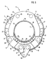
- the press ring (5) has essentially identical press jaw elements (6, 7, 8, 9, 10ildete), each press jaw element (6, 7, 8, 9, 10 ⁇ ) consisting of an external press jaw carrier (11, 12, 13, 14, 15) and an inner, arc-shaped press jaw (16, 17, 18, 19, 20 ⁇ ).
- the press jaw supports are connected to one another via intermediate pieces (21, 22, 23, 24), the press jaw supports (11, 12, 13, 14, 15) using articulated bolts (26, 27, 28, 29, 30 ⁇ , 31, 32, 33) are articulated on the intermediate pieces (21, 22, 23, 24).
- At least one hinge pin (26, 27, 28, 29, 30 ⁇ , 31, 32, 33) per intermediate piece (21, 22, 23, 24) is designed to be removable, so that the press ring (5) is divided into individual press jaw elements (6, 7, 8, 9, 10 ⁇ ) can be taken apart or assembled on site.
- the press jaws (16, 17, 18, 19, 20 ⁇ ) are slidably mounted in the circumferential direction in the press jaw carriers (11, 12, 13, 14, 15).
- a clamping device (34, 35, 36, 37, 38) is attached to each press jaw support (11, 12, 13, 14, 15), which has a clamping punch (39, 40 ⁇ , 41, 42, 43).
- the clamping devices (34, 35, 36, 37, 38) also serve to axially guide the press jaws (16, 17, 18, 19, 20 ⁇ ).
- the hinge pins (29, 30 ⁇ ) on the central press jaw support (13) carry a jaw-like gauge (44) in the form of a sheet metal part with a semicircular recess (45), the radius of the recess (45) being such that the gauge (44 ) fits on the one hand over the pipe end (1), but on the other hand does not fit over the cylindrical part of the press fitting (2) adjoining the annular bead (3).
- the lower press jaw elements (6, 10 ⁇ ) have between them a closing gap (46) in the positions shown in Figures (1) and (2). In the figures (1) it is so large that the press ring (5) can be put over the press fitting (2) and pipe end (1).
- the free ends of the pressing jaw elements (6, 10 ⁇ ) delimiting the closing gap (46) carry hinge pins (47, 48), a coupling lug (49, 50 ⁇ ) being suspended from each hinge pin (47, 48).
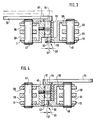
- the shape of the coupling straps (49, 50 ⁇ ) and their connection with the hinge pins (47, 48) result in particular from the sectional view according to Figures (3) and (4).
- the free ends of the coupling tabs (49, 50 ⁇ ) have through openings (51, 52).
- a coupling pin (53) is inserted axially. It has a first bolt section (54) with which it passes through the through hole (51).
- One end of the first bolt section (54) is connected to a hand lever (55).
- a second pin section (56) is formed on the other end of the first pin section (54), the axis of which is offset by an eccentricity (57) with respect to the axis of the first pin section (54).
- the second pin section (56) fits into the through hole (52) ) of the other coupling plate (50 ⁇ )
- the coupling plates (49, 50 ⁇ ) together with the coupling bolt (53) form a coupling element for the temporary connection of the ends of the pressing ring (5) before the actual pressing process.
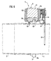
- the press jaws (16, 17, 18, 19, 20 ⁇ ) are not only axially guided by the clamping devices (34, 35, 36, 37, 38), but also by the other side of the press jaw carrier (11, 12, 13, 14, 15) screwed on guide plates (62).
- the press jaws (16, 17, 18, 19, 20 ⁇ ) themselves have an asymmetrical cross-sectional contour. They have an annular groove (63), the pressing grooves (63) of all pressing jaws (16, 17, 18, 19, 20 ⁇ ) complementing one another to form a continuous circumferential annular groove.
- the cross section of the press groove (63) is adapted to the annular bead (3), which carries a sealing ring (64) on the inside.
- a pressing web (65) runs along one side of the annular groove (63). It also complements the press bars of the other press jaws (16, 17, 18 19, 20 ⁇ ) to form a continuous circumferential press bar.
- the press web (65) is intended to dig into the material of the press fitting (2) during the pressing process and also to dig in to deform the pipe end (1). On the other side of the annular groove (63), such a press bar is not provided.
- the opened press ring (5) is first placed over the pipe end (1) and the press fitting (2), as can be seen from the figures (1) and (6).
- the two lower press jaw elements (6, 10 ⁇ ) are pivoted towards each other and onto the pipe end (1), so that they correspond to those shown in Figure (2 ) assume the position shown.
- the coupling straps (49, 50 ⁇ ) which then still hang down and are shown in dash-dot lines in this position in FIG. (2), are then pivoted in the directions of arrows C and D with respect to one another.
- the coupling bolt (53) is in such a position that its second bolt section (56) does not protrude through the through bore (51), which is indicated in FIG. (3) by the position of the hand lever (55) shown in dotted lines.
- the coupling lugs (49, 50 ⁇ ) are pivoted into a position where they overlap and the through holes (51, 52) merge into one another.
- the hand lever (55) are in such a position that the second bolt section (56) is offset in the direction of the other coupling plate (50 ⁇ ) and therefore easily in the through bore (52) by axial displacement of the Grip the coupling pin (53) so that both coupling brackets (49, 50 ⁇ ) can couple.
- the press ring (5) still has a certain amount of slack.
- the hand lever (55) is then pivoted from the position shown in solid lines in Figure (2) to the dash-dotted position in the direction of arrow E by 180 °.
- the second pin section (56) executes an eccentric movement and thereby shortens the distance between the two hinge pins (47, 48) by twice the eccentricity (57).
- Figures (3) and (4) with Figure (4) showing the pivoted position.
- a circumferential force is applied to the press ring (5) via which the press jaws (16, 17, 18, 19, 20 ⁇ ) press onto the press fitting (2) with a certain radial preload.
- the press ring (5) then has a seat that is difficult or impossible to turn. This effect is supported by the clamping rams (39, 40 ⁇ , 41, 42, 43), which then rest against the pipe end (1) with a likewise radially directed prestress.
- a locking device belonging to the pressing tool (4) is used, as is known schematically from Figure (7) of EP-A-0 ⁇ 451 80 ⁇ 6.
- This locking device has two pincer-shaped lever arms with which the locking device can be attached to the hinge pins (47, 48). They cover gaps (58, 59) or (60 ⁇ , 61) and then lay on the outside of the hinge pin (47, 48). The pliers-like lever arms are then moved together by means of a hydraulic motor belonging to the locking device, so that the hinge pins (47, 48) approach each other.
- the pressing ring (5) assumes the position shown in FIG. (5). After axial displacement of the coupling pin (53) in such a way that the second pin section (56) moves out of the through hole (52), the press ring (5) can be removed again and used for further pressing processes.
Landscapes
- Mechanical Engineering (AREA)
- Engineering & Computer Science (AREA)
- Automatic Assembly (AREA)
- Measurement Of The Respiration, Hearing Ability, Form, And Blood Characteristics Of Living Organisms (AREA)
- Hand Tools For Fitting Together And Separating, Or Other Hand Tools (AREA)
- Treatment Of Fiber Materials (AREA)
- Jigs For Machine Tools (AREA)
- Press Drives And Press Lines (AREA)
- Shaping Metal By Deep-Drawing, Or The Like (AREA)
- Apparatuses For Bulk Treatment Of Fruits And Vegetables And Apparatuses For Preparing Feeds (AREA)
- Finger-Pressure Massage (AREA)
- Perforating, Stamping-Out Or Severing By Means Other Than Cutting (AREA)
- Non-Disconnectible Joints And Screw-Threaded Joints (AREA)
- Wire Bonding (AREA)
- Gripping Jigs, Holding Jigs, And Positioning Jigs (AREA)
- Auxiliary Devices For And Details Of Packaging Control (AREA)
- Preventing Corrosion Or Incrustation Of Metals (AREA)
- Acyclic And Carbocyclic Compounds In Medicinal Compositions (AREA)
- Fats And Perfumes (AREA)
- Food-Manufacturing Devices (AREA)
Description
- Die Erfindung betrifft ein Preßwerkzeug zum Verpressen von rohrförmigen, ineinandergesteckten Werkstücken, insbesondere einem Rohrende und einem darübergestecktem Preßfitting, mit mehreren Preßbackenelementen, welche Preßbacken tragen, in die eine innenseitig jeweils in Umfangsrichtung verlaufende Preßnut eingeformt ist, die entlang nur einer Seite einen Preßsteg aufweist.
- Zur Verbindung von Rohrenden ist es bekannt, hülsenförmige Preßfittings zu verwenden, die plastisch verformbar sind und aus Metall, vorzugsweise aus Stahl bestehen. Solche Rohrverbindunen und die zugehörigen Preßfittings sind beispielsweise der DE-C-1 187 870̸ und der DE-C-40̸ 12 50̸4 zu entnehmen.
- Für das radiale Zusammenpressen von Preßfitting und Rohrende sind verschiedenste Formen von Preßwerkzeugen entwickelt worden. Diese Preßwerkzeuge haben Preßbackenelemente, die Preßbacken aufweisen, welche beim Verpressen radial zur Bildung eines geschlossenen Preßraumes bewegt werden. Dabei sind nicht nur Preßwerkzeuge mit zwei Preßbacken bekannt (DE-A-34 23 283; DE-A-38 33 748), sondern auch mit mehr als zwei Preßbacken, um höhere Einpreßtiefen verwirklichen zu können. Letztere Preßwerkzeuge sind insbesondere der EP-A-0̸ 451 80̸6 zu entnehmen. Dabei sind von besonderem Interesse die in den Figuren (7) und (8) dargestellten Preßwerkzeuge, da sie sich für das Verbinden von Rohrenden größeren und sehr großen Durchmessers eignen.
- Wie der gattungsgemäßen DE-C2-38 33 748 zu entnehmen ist, haben die Preßbacken solcher Preßwerkzeuge innenseitig eine bestimmte, an die Form des Preßfittings angepaßte Querschnittskontur. Da solche Preßfittinge am freien Ende einen nach außen vorstehenden Ringwulst aufweisen, in den innenseitig ein Dichtring eingelegt ist, hat die Preßbacke eine eingeformte Preßnut zur Aufnahme dieses Ringwulstes. Die einzelnen Abschnitte der Preßnut in den Preßbacken ergänzen sich zu einer über den Umfang durchgehenden Preßnut.
- Um nicht nur den Ringwulst auf das Rohrende zu pressen, sondern auch neben dem Ringwulst eine Verpressung zwischen Preßfitting und Rohrende zu bewirken, verlaufen zu beiden Seiten der Preßnut Preßstege, die sich beim Preßvorgang in das Material des Preßfittings und damit auch des eingesteckten Rohrendes einpressen. Wie der DE-C2-38 33 748 auch zu entnehmen ist, ist für das Funktionieren der Verpressung das Vorsehen von Preßstegen auf beiden Seiten der Preßnut nicht unbedingt erforderlich. Die Handhabung ist jedoch dann, wenn der Querschnitt der Preßbacken symmetrisch ist, also zu beiden Seiten der Preßnut Preßstege verlaufen, narrensicher, da es dann nicht darauf ankommt, in welcher Lage das Preßwerkzeug an die zu verpressende Stelle angelegt wird.
- Beim Einsatz eines Preßwerkzeuges der eingangs genannten Art mit symmetrischer Querschnittskontur der Preßbacken hat sich gezeigt, daß der auf der freien Seite des Preßfittings liegende Preßsteg in der Endphase des Preßvorgangs auch an dem Rohr zur Anlage kommt und dort zu einer Einschnürung des Rohres führt. Abgesehen davon, daß sich hierdurch die aufzuwendenden Preßkräfte erhöhen, wird die durch die Verpressung des Ringwulstes erzeugte elastische Vorspannung des Dichtrings verringert, so daß nicht mehr gewährleistet ist, daß die geforderte Dichtheit über Jahre hinweg erhalten bleibt. Im ungünstigsten Falle kann im Dichtsitzbereich sogar ein Spalt entstehen, der Undichtigkeiten nach sich zieht.
- Der Erfindung liegt deshalb die Aufgabe zugrunde, ein Preßwerkzeug der eingangs genannten Art so auszubilden, das unter Beibehaltung der Montagesicherheit ein Verpressen ohne Gefährdung der Dichtheit zuläßt.
- Diese Aufgabe wird erfindungsgemäß dadurch gelöst, daß zur anderen Seite hin eine Lehre angeordnet ist, die über das eingesteckte Werkstück, nicht jedoch über das aufgeschobene Werkstück paßt.
- Mit einem solchermaßen ausgebildeten Preßwerkzeug ist eine narrensichere Handhabung trotz der Tatsache gewährleistet, daß entlang nur einer Seite ein Preßsteg vorhanden ist. Es können somit die Vorteile von Preßwerkzeug mit unsymmetrischen Preßbacken verwirklicht werden, ohne daß hierdurch die Montagesicherheit leidet. Die Vorteile bestehen darin, daß Verformungen des Rohrs im Bereich des freien Endes des Preßfittings vermieden werden und damit die elastische Vorspannung des Dichtrings infolge der Verpressung des Ringwulstes nicht beeinträchtigt wird. Es ergänzen sich somit Montagesicherheit und die Gewährleistung der Dichtheit über Jahre.
- Dabei ist zu beachten, daß ein bestimmtes Preßwerkzeug nur zum Verpressen eines Werkstückes mit einem bestimmten Durchmesser paßt, die Bezugnahme auf das Werkstück also gleichzeitig eine Aussage über die Dimensionierung des Preßwerkzeuges beinhaltet. Die zusätzliche Anordnung einer Lehre verhindert, daß das Preßwerkzeug in einer falschen Stellung, bei der der Preßsteg auf der zum freien Ende des Preßfittings gerichteten Seite des Ringwulstes zu liegen kommt, auf die Preßstelle aufgesetzt wird, denn in dieser Stellung verhindert die Lehre ein Aufsetzen, weil sie nicht über den Preßfitting paßt. Erst in der umgekehrten Stellung, in der die Lehre außerhalb des Preßfittings zu liegen kommt, ist ein Anlegen des Preßwerkzeuges möglich.
- Die Lehre besteht in einer besonders einfachen Ausbildung aus einem entsprechend geformten Blechteil, das an einem der Preßbackenelemente befestigt ist.
- In der Zeichnung ist die Erfindung anhand eines Ausführungsbeispiels näher veranschaulicht. Es zeigen:
- Figur (1)
- den Preßring eines Preßwerkzeuges in geöffnetem Zustand;
- Figur (2)
- den Preßring gemäß Figur (1) in geschlossenem Zustand;
- Figur (3)
- einen Schnitt durch das Kupplungsglied des Preßrings gemäß den Figuren (1) und (2) in den Ebenen A-B in lockerer Kupplungsstellung;
- Figur (4)
- das Kupplungsglied in der Darstellung gemäß Figut (3) in gespanntem Zustand;
- Figur (5)
- den Preßring gemäß den Figuren (1) bis (4) in der Stellung nach der Verpressung und
- Figur (6)
- den Preßring mit Rohrende und Preßfitting in einem Axialschnitt in aufgesetztem Zustand.
- In den Figuren (1), (2) und (5) ist im Querschnitt und strickpunktiert ein innenliegendes Rohrende (1) sowie ein darauf aufgeschobenes Preßfitting (2) mit einem einen Dichtring enthaltenen Ringwulst (3) angedeutet. Rohrende (1) und Preßfitting (2) sollen mit Hilfe eines Preßwerkzeuges (4) verpreßt werden, von dem in den Figuren (1), (2) und (5) nur der Preßring (5) dargestellt ist.
- Der Preßring (5) weist bei diesem Ausführungsbeispiel im wesentlichen identisch ausgebildete Preßbackenelemente (6, 7, 8, 9, 10̸) auf, wobei jedes Preßbackenelement (6, 7, 8, 9, 10̸) aus einem außenliegenden Preßbackenträger (11, 12, 13, 14, 15) und einer innenliegenden, bogenförmigen Preßbacke (16, 17, 18, 19, 20̸) besteht. Bis auf eine Ausnahme sind die Preßbackenträger über Zwischenstücke (21, 22, 23, 24) miteinander verbunden, wobei die Preßbackenträger (11, 12, 13, 14, 15) über Gelenkbolzen (26, 27, 28, 29, 30̸, 31, 32, 33) an den Zwischenstücken (21, 22, 23, 24) angelenkt sind.
- Wenigstens jeweils ein Gelenkbolzen (26, 27, 28, 29, 30̸, 31, 32, 33) pro Zwischenstück (21, 22, 23, 24) ist herausnehmbar ausgebildet, so daß sich der Preßring (5) in einzelne Preßbackenelemente (6, 7, 8, 9, 10̸) auseinandernehmen oder aus diesen vor Ort zusammensetzen läßt. Die Preßbacken (16, 17, 18, 19, 20̸) sind in Umfangsrichtung verschieblich in den Preßbackenträgern (11, 12, 13, 14, 15) gelagert.
- An jedem Preßbackenträger (11, 12, 13, 14, 15) ist eine Klemmeinrichtung (34, 35, 36, 37, 38) angebracht, die einen radial nach innen gerichteten und unter Federvorspannung stehenden Klemmstempel (39, 40̸, 41, 42, 43) aufweist. Die Klemmeinrichtungen (34, 35, 36, 37, 38) dienen gleichzeitig der axialen Führung der Preßbacken (16, 17, 18, 19, 20̸).
- Die Gelenkbolzen (29, 30̸) an dem mittleren Preßbackenträger (13) tragen eine maulartige Lehre (44) in Form eines Blechteils mit einer halbkreisförmigen Ausnehmung (45), wobei der Radius der Ausnehmung (45) so bemesen ist, daß die Lehre (44) einerseits über das Rohrende (1) paßt, andererseits aber nicht über den an den Ringwulst (3) anschließenden, zylindrischen Teil des Preßfittings (2). Hierdurch ist gesichert, daß der Preßring (5) nur in einer, und zwar der vorgesehenen Stellung über die Kombination aus Rohrende (1) und Preßfitting (2) herumgelegt werden kann.
- Die unteren Preßbackenelemente (6, 10̸) haben in den in den Figuren (1) und (2) gezeigten Stellungen zwischen sich einen Schließspalt (46). In den Figuren (1) ist er so groß, daß der Preßring (5) über Preßfitting (2) und Rohrende (1) gestülpt werden kann. Die freien Enden der den Schließspalt (46) begrenzenden Preßbackenelemente (6, 10̸) tragen Gelenkbolzen (47, 48) wobei an jedem Gelenkbolzen (47, 48), jeweils eine Kupplungslasche (49, 50̸) aufgehängt ist. Die Formgebung der Kupplungslaschen (49, 50̸) und ihre Verbindung mit den Gelenkbolzen (47, 48) ergeben sich insbesondere aus der Schnittdarstellung gemäß den Figuren (3) und (4).
- Die freien Enden der Kupplungslaschen (49, 50̸) weisen Durchgangsöfnungen (51, 52) auf. In die Durchgangsbohrung (51) der Kupplungslasche (49) ist ein Kupplungsbolzen (53) axial verschieblich eingesetzt. Er weist einen ersten Bolzenabschnitt (54) auf, mit dem er die Durchgangsbohrung (51) durchfaßt. Ein Ende des ersten Bolzenabschnittes (54) ist mit einem Handhebel (55) verbunden. An dem anderen Ende des ersten Bolzenabschnittes (54) ist ein zweiter Bolzenabschnitt (56 angeformt, dessen Achse gegenüber der Achse des ersten Bolzenabschnittes (54) um eine Exentrizität (57) versetzt ist. Der zweite Bolzenabschnitt (56) paßt in die Durchgangsbohrung (52) der anderen Kupplungslasche (50̸). Die Kupplungslaschen (49, 50̸) bilden zusammen mit dem Kupplungsbolzen (53) ein Kupplungsglied zur provisorischen Verbindung der Enden des Preßrings (5) vor dem eigentlichen Preßvorgang.
- Wie sich aus der Darstellung gemäß Figur (6) ersehen läßt, werden die Preßbacken (16, 17, 18, 19, 20̸) nicht nur durch die Klemmeinrichtungen (34, 35, 36, 37, 38) axial geführt, sondern auch durch auf der anderen Seite der Preßbackenträger (11, 12, 13, 14, 15) aufgeschraubte Führungsplatten (62). Die Preßbacken (16, 17, 18, 19, 20̸) selbst haben eine asymmetrische Querschnittskontur. Sie weisen eine Ringnut (63) auf, wobei sich die Preßnuten (63) aller Preßbacken (16, 17, 18, 19, 20̸) zu einer durchgehenden Umfangsringnut ergänzen. Der Querschnitt der Preßnut (63) ist an den Ringwulst (3) angepaßt, welcher innenseitig einen Dichtring (64) trägt.
- Entlang einer Seite der Ringnut (63) verläuft ein Preßsteg (65). Auch er ergänzt sich mit den Preßstegen der anderen Preßbacken (16, 17, 18 19, 20̸) zu einem durchgehenden Umfangspreßsteg. Der Preßsteg (65) ist dazu bestimmt, sich beim Preßvorgang in das Material des Preßfittings (2) einzugraben und auch das Rohrende (1) zu verformen einzugraben. Auf der anderen Seite der Ringnut (63) ist ein solcher Preßsteg nicht vorgesehen.
- Für einen Preßvorgang wird zunächst der geöffnete Preßring (5) über das Rohrende (1) und den Preßfitting (2) gelegt, wie dies aus den Figuren (1) und (6) zu sehen ist. Wenn der Preßring (5) auf dem Rohrende (1) bzw. Preßfitting (2) aufsitzt, werden die beiden unteren Preßbackenelemente (6, 10̸) in Richtung zueinander und auf das Rohrende (1) verschwenkt, so daß sie die in Figur (2) gezeigte Stellung einnehmen. Die dann noch herunterhängenden, in dieser Stellung in Figur (2) strichpunktiert dargestellten Kupplungslaschen (49, 50̸) werden dann in die Richtungen der Pfeile C bzw. D zueinander verschwenkt. Dabei befindet sich der Kupplungsbolzen (53) in einer solchen Stellung, daß sein zweiter Bolzenabschnitt (56) nicht über die Durchgangsbohrung (51) vorsteht, was in Figur (3) durch die strickpunktiert gezeigte Stellung des Handhebels (55) angedeutet ist.
- Die Verschwenkung der Kupplungslaschen (49,50̸) geschieht bis in eine Stellung, wo sie sich überlappen und die Durchgangsbohrungen (51, 52) ineinander übergehen. Der Kupplungsbolzen (53) und damit der Handhebel (55) befinden sich dabei in einer solchen Stellung, daß der zweite Bolzenabschnitt (56) in Richtung auf die andere Kupplungslasche (50̸) versetzt ist und deshalb leicht in deren Durchgangsbohrung (52) durch axiale Verschiebung des Kupplungsbolzen (53) einfassen und damit beide Kupplungslaschen (49, 50̸) kuppeln kann. In dieser Stellung hat der Preßring (5) noch eine gewisse Lose.
- Der Handhebel (55) wird dann aus der in Figur (2) mit durchgezogenen Linien gezeigten Stellung in die strichpunktierte Stellung in Richtung des Pfeils E um 180̸° verschwenkt. Hierdurch führt der zweite Bolzenabschnitt (56) eine Exenterbewegung aus und verkürzt hierdurch den Abstand zwischen den beiden Gelenkbolzen (47, 48) um das Doppelte der Exentrizität (57). Diese wird aus dem Vergleich der Figuren (3) und (4) deutlich, wobei die Figur (4) die verschwenkte Stellung zeigt. Hierdurch wird dem Preßring (5) eine Umfangskraft aufgeprägt, über die die Preßbacken (16, 17, 18, 19, 20̸) mit einer gewissen Radialvorspannung auf das Preßfitting (2) aufdrücken. Der Preßring (5) hat dann einen nicht oder nur noch schwer verdrehbaren Sitz. Diese Wirkung wird durch die Klemmstempel (39, 40̸, 41, 42, 43) unterstützt, welche dann mit ebenfalls radial gerichteter Vorspannung an dem Rohrende (1) anliegen.
- Nun kann der eigentliche Preßvorgang beginnen. Hierzu wird eine nicht näher dargestellte, zum Preßwerkzeug (4) gehörende Schließeinrichtung verwendet, wie sie schematisch aus Figur (7) der EP-A-0̸ 451 80̸6 bekannt ist. Diese Schließeinrichtung hat zwei zangenförmige Hebelarme, mit denen die Schließeinrichtung an die Gelenkbolzen (47, 48) angesetzt werden kann. Sie durchfassen dabei Zwischenräume (58, 59) bzw. (60̸, 61) und legen sich dann an die Außenseiten der Gelenkbolzen (47, 48) an. Die zangenartigen Hebelarme werden dann mittels eines zur Schließeinrichtung gehörenden Hydraulikmotors zusammengefahren, so daß sich die Gelenkbolzen (47, 48) einander annähern. Dies hat zur Folge, daß sich der Preßring (5) zusammenzieht und hierdurch das Preßfitting (2) und das Rohrende (1) radial gestaucht werden, wobei sich der Preßsteg (65) in das Material des Preßfittings (2) ein wenig eingräbt und der Ringwulst (3) so gegen das Rohrende (1) gedrückt wird, daß der Dichtring (64) mit der für eine gute Abdichtung nötigen Radialkraft auf das Rohrende (1) gepreßt wird. Dabei verschieben sich die Preßbacken (16, 17, 18, 19, 20̸) in Anpassung an diesen Vorgang selbsttätig in Umfangsrichtung, und zwar solange, bis die Stirnseiten der Preßbacken (16, 17, 18, 19, 20̸) gegenseitig zur Anlage kommen. Gleichzeitig weichen die Kupplungslaschen (49, 50̸) nach außen aus, behindern also nicht den Preßvorgang. Nach Abschluß des Preßvorgangs nimmt der Preßring (5) die in Figur (5) gezeigte Stellung ein. Nach axialer Verschiebung des Kupplungsbolzen (53) in der Weise, daß der zweite Bolzenabschnitt (56) aus der Durchgangsbohrung (52) herausfährt, kann der Preßring (5) wieder abgenommen und für weitere Preßvorgänge benutzt werden.
Claims (3)
- Preßwerkzeug zum Verpressen von rohrförmigen, ineinandergesteckten Werkstücken (1, 2), insbesondere einem Rohrende (1) und einem darübergesteckten Preßfitting (2), mit mehreren Preßbackenelementen (6, 7, 8, 9, 10̸), welche Preßbacken (16, 17, 18, 19, 20̸) aufweisen, in die innenseitig eine jeweils in Umfangsrichtung verlaufende Preßnut (63) eingeformt ist, die entlang nur einer Seite einen Preßsteg (65) aufweist,
dadurch gekennzeichnet, daß zur anderen Seite hin eine Lehre (44) angeordnet ist, die über das eingesteckte Werkstück (1), nicht jedoch über das aufgeschobene Werkstück (2) paßt. - Preßwerkzeug nach Anspruch (1),
dadurch gekennzeichnet, daß die Lehre (44) maulartig geformt ist. - Preßwerkzeug nach Anspruch (1) oder (2),
dadurch gekennzeichnet, daß die Lehre aus einem Blechteil besteht, das an einem der Preßbackenelemente (8) befestigt ist.
Applications Claiming Priority (3)
| Application Number | Priority Date | Filing Date | Title |
|---|---|---|---|
| DE9216369U DE9216369U1 (de) | 1992-12-02 | 1992-12-02 | Preßwerkzeug |
| DE9216369U | 1992-12-02 | ||
| PCT/EP1993/003302 WO1994012297A1 (de) | 1992-12-02 | 1993-11-25 | Presswerkzeug |
Publications (2)
| Publication Number | Publication Date |
|---|---|
| EP0671985A1 EP0671985A1 (de) | 1995-09-20 |
| EP0671985B1 true EP0671985B1 (de) | 1996-08-28 |
Family
ID=6886640
Family Applications (1)
| Application Number | Title | Priority Date | Filing Date |
|---|---|---|---|
| EP94901870A Expired - Lifetime EP0671985B1 (de) | 1992-12-02 | 1993-11-25 | Presswerkzeug |
Country Status (20)
| Country | Link |
|---|---|
| US (1) | US5697135A (de) |
| EP (1) | EP0671985B1 (de) |
| JP (1) | JPH08503662A (de) |
| CN (1) | CN1093957A (de) |
| AT (1) | ATE141835T1 (de) |
| AU (1) | AU669039B2 (de) |
| BR (1) | BR9307578A (de) |
| CA (1) | CA2150811C (de) |
| CZ (1) | CZ282551B6 (de) |
| DE (2) | DE9216369U1 (de) |
| DK (1) | DK0671985T3 (de) |
| ES (1) | ES2093511T3 (de) |
| FI (1) | FI952672A0 (de) |
| GR (1) | GR3021325T3 (de) |
| HU (1) | HUT71167A (de) |
| NO (1) | NO952176D0 (de) |
| NZ (1) | NZ258548A (de) |
| PL (1) | PL171755B1 (de) |
| SK (1) | SK66595A3 (de) |
| WO (1) | WO1994012297A1 (de) |
Families Citing this family (32)
| Publication number | Priority date | Publication date | Assignee | Title |
|---|---|---|---|---|
| DE4240427C1 (de) * | 1992-12-02 | 1994-01-20 | Novopress Gmbh | Preßwerkzeug |
| DE9312808U1 (de) * | 1993-08-26 | 1993-10-28 | Novopress GmbH Pressen und Presswerkzeuge & Co KG, 41460 Neuss | Meßgerät zur Erfassung der Einschubtiefe bei einer Rohrverbindung |
| RU2133401C1 (ru) * | 1997-06-25 | 1999-07-20 | Хасанов Ильмер Юсупович | Способ ремонта дефектов трубопровода |
| DE19734355C2 (de) * | 1997-08-08 | 2002-08-14 | Uponor Rohrsysteme Gmbh | Preßwerkzeug |
| DE29721759U1 (de) * | 1997-12-10 | 1998-04-09 | Franz Viegener II GmbH & Co. KG, 57439 Attendorn | Preßwerkzeug zum unlösbaren Verbinden eines Fittings und eines eingeführten Metallrohrendes |
| US6185980B1 (en) * | 1999-09-23 | 2001-02-13 | Leonard J. Law | Special crimping tool |
| ES2223362T3 (es) | 1999-10-26 | 2005-03-01 | Ridge Tool Ag | Una herramienta compresora y el metodo para unir piezas mediante deformacion en frio. |
| ES2254784T3 (es) * | 2001-12-08 | 2006-06-16 | Gustav Klauke Gmbh | Dispositivo de prensa. |
| US20030230132A1 (en) * | 2002-06-17 | 2003-12-18 | Emerson Electric Co. | Crimping apparatus |
| US7398909B2 (en) * | 2003-07-17 | 2008-07-15 | Swagelok Company | Pipe collets |
| WO2007038308A1 (en) | 2005-09-23 | 2007-04-05 | Bruns Daniel Kidd | Tool to crimp non-metallic tubing onto fittings |
| DE102006050427A1 (de) * | 2006-08-22 | 2008-02-28 | Gustav Klauke Gmbh | Verfahren zum Verpressen eines Pressfittings sowie Presswerkzeug hierzu |
| JP5396273B2 (ja) * | 2006-10-20 | 2014-01-22 | グスタフ・クラウケ・ゲーエムベーハー | プレス継手のプレス方法及びそのプレス工具 |
| US20080122222A1 (en) * | 2006-11-29 | 2008-05-29 | H & H Tube & Manufacturing Co. | Crimp-on transition fitting |
| KR100739106B1 (ko) * | 2006-12-20 | 2007-07-12 | 웰텍 주식회사 | 강관 맞대기용 정형이음장치 |
| US7980522B2 (en) * | 2007-12-28 | 2011-07-19 | Alion Science And Technology Corporation | Trailing edge blade clamp |
| US8230714B2 (en) * | 2009-01-23 | 2012-07-31 | Custom Machining Services, Inc. | Die carrier assembly and crimping process |
| US20100253066A1 (en) * | 2009-04-02 | 2010-10-07 | Victaulic Company | Crimp-Type Coupling, Crimping Tool and Method of Crimping |
| DE202009009456U1 (de) * | 2009-07-15 | 2010-11-25 | Novopress Gmbh Pressen Und Presswerkzeuge & Co. Kommanditgesellschaft | Presswerkzeug zum Verbinden von insbesondere rohrförmigen Werkstücken |
| DE102009059053A1 (de) * | 2009-12-15 | 2011-06-16 | REMS-WERK Christian Föll und Söhne GmbH | Presswerkzeug zum Radialverpressen von Werkstücken sowie Werkzeug mit wenigstens zwei relativ zueinander bewegbaren Werkzeugteilen |
| CN101890457A (zh) * | 2010-06-25 | 2010-11-24 | 浙江毅力汽车空调有限公司 | 管路接头压接工具 |
| FR2965199B1 (fr) * | 2010-09-24 | 2012-09-07 | Serimax | Bride d'aide au travail de tubes comportant plusieurs parties. |
| DE102011052852A1 (de) * | 2011-08-19 | 2013-02-21 | Gustav Klauke Gmbh | Pressvorrichtung |
| DE202011105967U1 (de) | 2011-09-21 | 2011-12-06 | Mehmet Saldiray Atac | Presswerkzeug-Mehrfachgrössenkopf |
| CN102805676B (zh) * | 2012-08-14 | 2015-06-17 | 杭州启明医疗器械有限公司 | 人造瓣膜置换装置的压缩装置 |
| US9388885B2 (en) | 2013-03-15 | 2016-07-12 | Ideal Industries, Inc. | Multi-tool transmission and attachments for rotary tool |
| EP3548258B1 (de) * | 2017-03-30 | 2022-05-04 | IPS, Corporation - Weld-On Division | Rohrkupplungsvorrichtung und verfahren |
| CN108620498B (zh) * | 2018-04-28 | 2020-11-03 | 浙江康帕斯流体输送技术有限公司 | 一种卡压式管件的环压工具 |
| KR200491617Y1 (ko) * | 2019-01-21 | 2020-05-11 | 민우정공(주) | 배관용 압착 체결구 |
| CN110052991A (zh) * | 2019-05-24 | 2019-07-26 | 成都川力美亚管业有限公司 | 一种连接稳定的环压管件工具 |
| DE102019118588A1 (de) * | 2019-07-09 | 2021-01-14 | Daniel Knipping | Quetschhülse für Rohrverbindungen |
| DE102023111833A1 (de) | 2023-05-05 | 2024-11-07 | Oetiker Schweiz Ag | Crimpbackenanordnung und Crimpwerkzeug |
Family Cites Families (11)
| Publication number | Priority date | Publication date | Assignee | Title |
|---|---|---|---|---|
| DE1187870B (de) * | 1958-10-01 | 1965-02-25 | Aga Plaatfoeraedling Aktiebola | Plastisch verformbare metallische Kupplungshuelse zum Verbinden von Metallrohren mit glatten Enden |
| US3756064A (en) * | 1972-03-24 | 1973-09-04 | Waldes Kohinoor Inc | Hand-operated plier-like tools |
| NL149406B (nl) * | 1973-10-02 | 1976-05-17 | Hubert Joseph Mertens | Pijpenklem. |
| DE3423283A1 (de) * | 1984-06-23 | 1986-01-02 | Helmut Dipl.-Ing. 4040 Neuss Dischler | Klemmwerkzeug, insbesondere zum verbinden von rohren und anderen profilen |
| US4934673A (en) * | 1987-12-10 | 1990-06-19 | General Dynamics Corp., Pomona Division | V-clamp installation tool |
| DE3833748A1 (de) * | 1988-09-30 | 1990-04-05 | Mannesmann Ag | Verfahren und vorrichtung zur herstellung einer unloesbaren, dichten verbindung von rohren |
| DE58901633D1 (de) * | 1988-09-30 | 1992-07-16 | Mannesmann Ag | Verfahren und vorrichtung und pressfitting zur herstellung einer unloesbaren, dichten verbindung von rohren. |
| US5209100A (en) * | 1990-04-12 | 1993-05-11 | Helmut Dischler | Compression tool |
| DE9007414U1 (de) * | 1990-04-12 | 1991-07-18 | Dischler, Helmut, Dipl.-Ing., 4040 Neuss | Preßwerkzeug |
| DE4036915A1 (de) * | 1990-11-20 | 1992-05-21 | Chiron Werke Gmbh | Werkzeugmaschine und verfahren zum oeffnen und schliessen eines greifers |
| DE9103264U1 (de) * | 1991-03-18 | 1991-06-20 | Hewing GmbH, 4434 Ochtrup | Preßzange für das Verpressen von Rohrverbindungen |
-
1992
- 1992-12-02 DE DE9216369U patent/DE9216369U1/de not_active Expired - Lifetime
-
1993
- 1993-11-25 WO PCT/EP1993/003302 patent/WO1994012297A1/de not_active Ceased
- 1993-11-25 ES ES94901870T patent/ES2093511T3/es not_active Expired - Lifetime
- 1993-11-25 CA CA002150811A patent/CA2150811C/en not_active Expired - Fee Related
- 1993-11-25 EP EP94901870A patent/EP0671985B1/de not_active Expired - Lifetime
- 1993-11-25 JP JP6512759A patent/JPH08503662A/ja active Pending
- 1993-11-25 DE DE59303597T patent/DE59303597D1/de not_active Expired - Fee Related
- 1993-11-25 FI FI952672A patent/FI952672A0/fi not_active Application Discontinuation
- 1993-11-25 PL PL93309047A patent/PL171755B1/pl unknown
- 1993-11-25 CZ CZ951380A patent/CZ282551B6/cs unknown
- 1993-11-25 SK SK665-95A patent/SK66595A3/sk unknown
- 1993-11-25 HU HU9501521A patent/HUT71167A/hu unknown
- 1993-11-25 NZ NZ258548A patent/NZ258548A/en unknown
- 1993-11-25 DK DK94901870.9T patent/DK0671985T3/da active
- 1993-11-25 US US08/448,437 patent/US5697135A/en not_active Expired - Lifetime
- 1993-11-25 AT AT94901870T patent/ATE141835T1/de not_active IP Right Cessation
- 1993-11-25 BR BR9307578-2A patent/BR9307578A/pt not_active Application Discontinuation
- 1993-11-25 AU AU56273/94A patent/AU669039B2/en not_active Ceased
- 1993-12-01 CN CN93120082A patent/CN1093957A/zh active Pending
-
1995
- 1995-06-01 NO NO952176A patent/NO952176D0/no unknown
-
1996
- 1996-10-10 GR GR960402688T patent/GR3021325T3/el unknown
Also Published As
| Publication number | Publication date |
|---|---|
| PL171755B1 (pl) | 1997-06-30 |
| ES2093511T3 (es) | 1996-12-16 |
| DE9216369U1 (de) | 1993-02-04 |
| PL309047A1 (en) | 1995-09-18 |
| DK0671985T3 (da) | 1996-12-02 |
| SK66595A3 (en) | 1996-03-06 |
| CA2150811A1 (en) | 1994-06-09 |
| CA2150811C (en) | 2001-05-29 |
| FI952672A7 (fi) | 1995-06-01 |
| HUT71167A (en) | 1995-11-28 |
| ATE141835T1 (de) | 1996-09-15 |
| NO952176L (no) | 1995-06-01 |
| US5697135A (en) | 1997-12-16 |
| AU5627394A (en) | 1994-06-22 |
| AU669039B2 (en) | 1996-05-23 |
| HU9501521D0 (en) | 1995-07-28 |
| DE59303597D1 (de) | 1996-10-02 |
| JPH08503662A (ja) | 1996-04-23 |
| NO952176D0 (no) | 1995-06-01 |
| BR9307578A (pt) | 1999-08-31 |
| CZ282551B6 (cs) | 1997-08-13 |
| GR3021325T3 (en) | 1997-01-31 |
| FI952672A0 (fi) | 1995-06-01 |
| NZ258548A (en) | 1997-07-27 |
| CZ138095A3 (en) | 1996-04-17 |
| CN1093957A (zh) | 1994-10-26 |
| EP0671985A1 (de) | 1995-09-20 |
| WO1994012297A1 (de) | 1994-06-09 |
Similar Documents
| Publication | Publication Date | Title |
|---|---|---|
| EP0671985B1 (de) | Presswerkzeug | |
| EP0671984B1 (de) | Presswerkzeug | |
| EP0452791B1 (de) | Presswerkzeug | |
| DE69810362T2 (de) | Dichtverbindung zwischen Fluidbohrungen | |
| DE2911708C2 (de) | Rohrverbindungsanordnung, insbesondere für Gasrohrleitungsnetze oder dergleichen, und Verfahren und Vorrichtung zur Herstellung von derartigen Rohrverbindungsanordnungen | |
| DE60305236T2 (de) | Verbindungsvorrichtung zur Verbindung von zwei Rohren | |
| EP1455969A1 (de) | Pressvorrichtung | |
| DE19701857C2 (de) | Geschlitzter Befestigungsring | |
| DE3226868A1 (de) | Dauerhaft dichte gewindelose rohrverbindung | |
| DE1934339A1 (de) | Verfahren und Vorrichtung zum dauerhaften Verbinden von umlaufenden Teilen,wie Wellenteilen od.dgl.,mittels Kerbverzahnung | |
| EP3308066A1 (de) | Schelle mit schellenband und vorpositionierer | |
| DE1450396A1 (de) | Dichtverbindung fuer stroemungsfaehige Medien | |
| EP0774611A1 (de) | Verfahren zur Herstellung einer Rohrverbindung sowie Kupplungsvorrichtung für die Herstellung einer Rohrverbindung | |
| EP1535677B1 (de) | Presswerkzeug | |
| CH656199A5 (de) | Verbindungselement zum kuppeln zweier flansche. | |
| DE69121548T2 (de) | Verbesserte Bandschelle mit keilförmigen, geschlitzten Nocken | |
| DE2133446A1 (de) | Axialspannfutter | |
| WO2003062694A1 (de) | Rohrpresskupplung | |
| EP1793155B1 (de) | Rohrschelle, insbesondere Anbohrschelle | |
| DE29517518U1 (de) | Preßwerkzeug | |
| DE102020202867A1 (de) | Presskette | |
| EP0554699B1 (de) | Vorrichtung zum Runddrücken von Rohren | |
| DE102020131455B4 (de) | Verbindungssystem | |
| WO1996021531A1 (de) | Verfahren zum verbinden eines pressfittings mit einem rohrende sowie pressgerät zur durchführung dieses verfahrens | |
| DE2545518A1 (de) | Rohrklemm- und dichtungskupplung fuer unterwasser-pipelines |
Legal Events
| Date | Code | Title | Description |
|---|---|---|---|
| PUAI | Public reference made under article 153(3) epc to a published international application that has entered the european phase |
Free format text: ORIGINAL CODE: 0009012 |
|
| 17P | Request for examination filed |
Effective date: 19950512 |
|
| AK | Designated contracting states |
Kind code of ref document: A1 Designated state(s): AT BE CH DE DK ES FR GB GR IT LI NL PT SE |
|
| GRAG | Despatch of communication of intention to grant |
Free format text: ORIGINAL CODE: EPIDOS AGRA |
|
| GRAH | Despatch of communication of intention to grant a patent |
Free format text: ORIGINAL CODE: EPIDOS IGRA |
|
| 17Q | First examination report despatched |
Effective date: 19960215 |
|
| GRAH | Despatch of communication of intention to grant a patent |
Free format text: ORIGINAL CODE: EPIDOS IGRA |
|
| GRAA | (expected) grant |
Free format text: ORIGINAL CODE: 0009210 |
|
| AK | Designated contracting states |
Kind code of ref document: B1 Designated state(s): AT BE CH DE DK ES FR GB GR IT LI NL PT SE |
|
| REF | Corresponds to: |
Ref document number: 141835 Country of ref document: AT Date of ref document: 19960915 Kind code of ref document: T |
|
| ET | Fr: translation filed | ||
| REF | Corresponds to: |
Ref document number: 59303597 Country of ref document: DE Date of ref document: 19961002 |
|
| GBT | Gb: translation of ep patent filed (gb section 77(6)(a)/1977) |
Effective date: 19961003 |
|
| ITF | It: translation for a ep patent filed | ||
| PGFP | Annual fee paid to national office [announced via postgrant information from national office to epo] |
Ref country code: PT Payment date: 19961118 Year of fee payment: 4 |
|
| PGFP | Annual fee paid to national office [announced via postgrant information from national office to epo] |
Ref country code: DK Payment date: 19961125 Year of fee payment: 4 |
|
| PGFP | Annual fee paid to national office [announced via postgrant information from national office to epo] |
Ref country code: GR Payment date: 19961127 Year of fee payment: 4 |
|
| REG | Reference to a national code |
Ref country code: DK Ref legal event code: T3 |
|
| REG | Reference to a national code |
Ref country code: ES Ref legal event code: FG2A Ref document number: 2093511 Country of ref document: ES Kind code of ref document: T3 |
|
| REG | Reference to a national code |
Ref country code: GR Ref legal event code: FG4A Free format text: 3021325 |
|
| SC4A | Pt: translation is available |
Free format text: 961004 AVAILABILITY OF NATIONAL TRANSLATION |
|
| PLBE | No opposition filed within time limit |
Free format text: ORIGINAL CODE: 0009261 |
|
| STAA | Information on the status of an ep patent application or granted ep patent |
Free format text: STATUS: NO OPPOSITION FILED WITHIN TIME LIMIT |
|
| 26N | No opposition filed | ||
| PG25 | Lapsed in a contracting state [announced via postgrant information from national office to epo] |
Ref country code: DK Free format text: LAPSE BECAUSE OF NON-PAYMENT OF DUE FEES Effective date: 19971125 |
|
| PG25 | Lapsed in a contracting state [announced via postgrant information from national office to epo] |
Ref country code: GR Free format text: LAPSE BECAUSE OF NON-PAYMENT OF DUE FEES Effective date: 19971130 |
|
| PG25 | Lapsed in a contracting state [announced via postgrant information from national office to epo] |
Ref country code: PT Free format text: LAPSE BECAUSE OF NON-PAYMENT OF DUE FEES Effective date: 19980531 |
|
| REG | Reference to a national code |
Ref country code: PT Ref legal event code: MM4A Free format text: LAPSE DUE TO NON-PAYMENT OF FEES Effective date: 19980531 |
|
| PGFP | Annual fee paid to national office [announced via postgrant information from national office to epo] |
Ref country code: SE Payment date: 19991119 Year of fee payment: 7 Ref country code: AT Payment date: 19991119 Year of fee payment: 7 |
|
| PGFP | Annual fee paid to national office [announced via postgrant information from national office to epo] |
Ref country code: NL Payment date: 19991122 Year of fee payment: 7 |
|
| PGFP | Annual fee paid to national office [announced via postgrant information from national office to epo] |
Ref country code: BE Payment date: 19991123 Year of fee payment: 7 |
|
| PGFP | Annual fee paid to national office [announced via postgrant information from national office to epo] |
Ref country code: ES Payment date: 19991125 Year of fee payment: 7 |
|
| REG | Reference to a national code |
Ref country code: DK Ref legal event code: EBP |
|
| PG25 | Lapsed in a contracting state [announced via postgrant information from national office to epo] |
Ref country code: AT Free format text: LAPSE BECAUSE OF NON-PAYMENT OF DUE FEES Effective date: 20001125 |
|
| PG25 | Lapsed in a contracting state [announced via postgrant information from national office to epo] |
Ref country code: ES Free format text: LAPSE BECAUSE OF NON-PAYMENT OF DUE FEES Effective date: 20001126 |
|
| PG25 | Lapsed in a contracting state [announced via postgrant information from national office to epo] |
Ref country code: SE Free format text: THE PATENT HAS BEEN ANNULLED BY A DECISION OF A NATIONAL AUTHORITY Effective date: 20001129 |
|
| PG25 | Lapsed in a contracting state [announced via postgrant information from national office to epo] |
Ref country code: BE Free format text: LAPSE BECAUSE OF NON-PAYMENT OF DUE FEES Effective date: 20001130 |
|
| BERE | Be: lapsed |
Owner name: NOVOPRESS G.M.B.H. PRESSEN UND PRESSWERKZEUGE & C Effective date: 20001130 |
|
| PG25 | Lapsed in a contracting state [announced via postgrant information from national office to epo] |
Ref country code: NL Free format text: LAPSE BECAUSE OF NON-PAYMENT OF DUE FEES Effective date: 20010601 |
|
| EUG | Se: european patent has lapsed |
Ref document number: 94901870.9 |
|
| NLV4 | Nl: lapsed or anulled due to non-payment of the annual fee |
Effective date: 20010601 |
|
| PGFP | Annual fee paid to national office [announced via postgrant information from national office to epo] |
Ref country code: GB Payment date: 20011102 Year of fee payment: 9 |
|
| PGFP | Annual fee paid to national office [announced via postgrant information from national office to epo] |
Ref country code: DE Payment date: 20011113 Year of fee payment: 9 |
|
| PGFP | Annual fee paid to national office [announced via postgrant information from national office to epo] |
Ref country code: FR Payment date: 20011119 Year of fee payment: 9 |
|
| PGFP | Annual fee paid to national office [announced via postgrant information from national office to epo] |
Ref country code: CH Payment date: 20011126 Year of fee payment: 9 |
|
| REG | Reference to a national code |
Ref country code: GB Ref legal event code: IF02 |
|
| PG25 | Lapsed in a contracting state [announced via postgrant information from national office to epo] |
Ref country code: GB Free format text: LAPSE BECAUSE OF NON-PAYMENT OF DUE FEES Effective date: 20021125 |
|
| PG25 | Lapsed in a contracting state [announced via postgrant information from national office to epo] |
Ref country code: LI Free format text: LAPSE BECAUSE OF NON-PAYMENT OF DUE FEES Effective date: 20021130 Ref country code: CH Free format text: LAPSE BECAUSE OF NON-PAYMENT OF DUE FEES Effective date: 20021130 |
|
| PG25 | Lapsed in a contracting state [announced via postgrant information from national office to epo] |
Ref country code: DE Free format text: LAPSE BECAUSE OF NON-PAYMENT OF DUE FEES Effective date: 20030603 |
|
| REG | Reference to a national code |
Ref country code: CH Ref legal event code: PL |
|
| GBPC | Gb: european patent ceased through non-payment of renewal fee | ||
| PG25 | Lapsed in a contracting state [announced via postgrant information from national office to epo] |
Ref country code: FR Free format text: LAPSE BECAUSE OF NON-PAYMENT OF DUE FEES Effective date: 20030731 |
|
| REG | Reference to a national code |
Ref country code: FR Ref legal event code: ST |
|
| REG | Reference to a national code |
Ref country code: ES Ref legal event code: FD2A Effective date: 20011214 |
|
| PG25 | Lapsed in a contracting state [announced via postgrant information from national office to epo] |
Ref country code: IT Free format text: LAPSE BECAUSE OF NON-PAYMENT OF DUE FEES;WARNING: LAPSES OF ITALIAN PATENTS WITH EFFECTIVE DATE BEFORE 2007 MAY HAVE OCCURRED AT ANY TIME BEFORE 2007. THE CORRECT EFFECTIVE DATE MAY BE DIFFERENT FROM THE ONE RECORDED. Effective date: 20051125 |