EP1398993A2 - Vorrichtung und Verfahren zur Rückkopplungskompensation in einem akustischen Verstärkungssystem, insbesondere in einem Hörnhilfsgerät - Google Patents
Vorrichtung und Verfahren zur Rückkopplungskompensation in einem akustischen Verstärkungssystem, insbesondere in einem Hörnhilfsgerät Download PDFInfo
- Publication number
- EP1398993A2 EP1398993A2 EP03019877A EP03019877A EP1398993A2 EP 1398993 A2 EP1398993 A2 EP 1398993A2 EP 03019877 A EP03019877 A EP 03019877A EP 03019877 A EP03019877 A EP 03019877A EP 1398993 A2 EP1398993 A2 EP 1398993A2
- Authority
- EP
- European Patent Office
- Prior art keywords
- filter
- feedback
- signal
- compensator
- compensation
- Prior art date
- Legal status (The legal status is an assumption and is not a legal conclusion. Google has not performed a legal analysis and makes no representation as to the accuracy of the status listed.)
- Granted
Links
Images



Classifications
-
- H—ELECTRICITY
- H04—ELECTRIC COMMUNICATION TECHNIQUE
- H04R—LOUDSPEAKERS, MICROPHONES, GRAMOPHONE PICK-UPS OR LIKE ACOUSTIC ELECTROMECHANICAL TRANSDUCERS; ELECTRIC HEARING AIDS; PUBLIC ADDRESS SYSTEMS
- H04R25/00—Electric hearing aids
- H04R25/45—Prevention of acoustic reaction, i.e. acoustic oscillatory feedback
- H04R25/453—Prevention of acoustic reaction, i.e. acoustic oscillatory feedback electronically
-
- H—ELECTRICITY
- H04—ELECTRIC COMMUNICATION TECHNIQUE
- H04R—LOUDSPEAKERS, MICROPHONES, GRAMOPHONE PICK-UPS OR LIKE ACOUSTIC ELECTROMECHANICAL TRANSDUCERS; ELECTRIC HEARING AIDS; PUBLIC ADDRESS SYSTEMS
- H04R3/00—Circuits for transducers
- H04R3/02—Circuits for transducers for preventing acoustic reaction, i.e. acoustic oscillatory feedback
Definitions
- the invention relates to a feedback compensator in one acoustic amplification system for compensation of a feedback signal, that with an amplification of an input signal due to a feedback path from an amplified one Output signal to the input signal arises with a adaptive feedback compensation filter based on the amplified output signal generates a compensation signal, and with a first filter that limits the frequency range, in which the compensation signal is generated.
- the invention also relates to a hearing aid with a such feedback compensator.
- the invention relates to a method for Compensation of a feedback signal in an acoustic System, wherein the feedback signal when amplified of an input signal due to a feedback path of an amplified output signal on the input signal arises, and wherein an adaptive feedback compensation filter a compensation signal to simulate the feedback signal generated from the amplified output signal.
- the invention also relates to an application of the method in a hearing aid.
- a compensation signal is generated, which is subtracted from the input signal before amplification and that is such that a feedback causing frequency is reduced to an intensity that is below a so-called stability limit.
- the feedback compensation path is generated with the adaptive feedback compensation filter, which is usually a So-called FIR filter (FIR: Finite Impulse Response). This generates a filtering of the amplified output signal the compensation signal.
- the feedback compensation filter is set with an adaptation unit, the for example based on filter coefficients of the feedback compensation filter tries the effect of the feedback compensation filter so that an error signal, mostly the input signal just before it enters the amplification system, minimized to the smallest signal energy becomes. For such an optimization, the error signal and the output signal from the adaptation unit using an LMS function (least mean square) compared.
- the adaptation of the coefficients must not be too fast or too slow; it is characterized by the adaptation step size, i.e. the change in the coefficients, and by the speed, with the new coefficient to the feedback compensation filter be transmitted.
- various feedback compensators are off WO 00/19605 known.
- the bandwidth of the compensation signal limited to interference due to the feedback compensation filter to minimize and on the unstable Limit frequency range.
- the limitation of the frequency range has the disadvantage that it is unstable with one Frequency range-selecting filter is performed.
- the Frequency range of the feedback can vary during the Change application, for example due to an additional one Gap between an in-the-ear hearing aid and the Ear canal of the hearing aid wearer or due to changing external acoustic framework conditions such as wearing a Helms. This quickly leads to a too wide, too narrow or completely wrong limitation of the frequency range with a correspondingly inadequate function of the feedback compensator and thus the hearing aid.
- the invention is based on the object of a feedback compensator, a hearing aid with a feedback compensator, a method for compensating a feedback signal in an acoustic amplification system and an application to specify such a procedure that is effective and enable fast feedback compensation with high sound quality.
- the filter function describes this of a filter, the transfer function, i.e. the transmission the filter at a given frequency. she decides hence the frequency range in which the filter acts.
- 'Adaptable in its filter function' means in Sense of the invention that the filter function due to the Feedback situation is changeable.
- the first filter has the advantage that the first filter automatically to the currently unstable frequency range can be customized. This also allows the process of Feedback compensation with respect to the frequency range automatically be optimized so that the feedback compensation very effective and fast with minimal artifacts in the amplified Output signal can be carried out.
- the feedback compensator a learning ability due to an adaptation process can have with regard to the filter function. This allows it, the first filter initially based on experience or measurement basic setting. It comes during using the feedback compensation filter to one Feedback at another, from the feedback compensator uncovered frequency to a feedback, the Filter function can be extended to this frequency range.
- Such an adaptive system can e.g. also perform tests, which check whether the one captured by the filter function Frequency range is set too wide. If so, it can Frequency range can be reduced accordingly. This causes Accelerated feedback compensation with fewer artifacts.
- the first filter consisting of several individual filters. Together these result the filter function of the first filter.
- the advantage of one Such a modular filter structure lies in the diverse Setting option of the filter function.
- a simple realization the adaptability of the frequency range of the first Filters then consists of switching between two or several individual filters to the frequency range of the present Adapt feedback.
- the filter function of the first filter is adjustable Coefficients changeable. This has the advantage that one all necessary filter functions with a single adjustable filter can realize.
- the feedback compensator is the amplified output signal over the first filter connected to the feedback compensation filter. This has the advantage that the first filter is primary affects the feedback compensation path.
- the feedback compensator a control unit for adapting the first filter on.
- a control unit can be a changeover switch, for example to choose the individual filter or it can be medium for setting filter coefficients of the first filter exhibit.
- the feedback compensator an analysis unit for checking the feedback compensation on.
- Such an analysis unit can, for example the parameters of the adaptive feedback compensation filter check and use the filter parameters of the compare first filter. From a good match the filter functions can be inferred, for example, that the first filter on the feedback compensation filter is ideally adapted. A bad match of the filter functions may indicate the need for a further adaptation step to adjust the filter function of the first filter Clues.
- the analysis unit has Means for comparing the input signal with the filtered Output signal on. Such a comparison can find out whether and in what frequency range feedback is present. The frequency range of the first filter can then be adjusted.
- the analysis unit comprises an oscillation detector, that for measuring feedback in the amplified Frequency range is used.
- an oscillation detector that for measuring feedback in the amplified Frequency range is used.
- the acoustic feedback path both the transmission of the Feedback via structure-borne noise as well as airborne noise.
- the Structure-borne noise can, for example, by suitable reinforcements of the hearing aid housing, i.e. prevented by construction measures become.
- airborne noise is general harder to control.
- it depends on the Adaptation of an in-the-ear hearing aid to the anatomical conditions from and on the other hand he can, for example due to deformation of the anatomy when chewing or yawning or change due to changes in the acoustic environment.
- An exception is airborne sound, which e.g. along the ventilation hole leads to feedback. Because this feedback path for example, he cannot change anything at the Signal processing are taken into account.
- the feedback compensator is used the compensation of an electromagnetic feedback path.
- an electromagnetic feedback path one understands e.g. the feedback from the speaker coil on the telecoil by electromagnetic fields, which at the Function of the speaker emitted and from the telecoil be received.
- the advantage of the feedback compensator according to the invention lies in its flexibility over the possible feedback paths.
- the adaptive feedback compensation filter an adaptation unit which e.g. to minimize the error signal energy with that acting as an error signal Input signal is connected.
- an adaptation unit which e.g. to minimize the error signal energy with that acting as an error signal Input signal is connected.
- the adaptation unit with the output of the first filter connected via a third filter. This has the advantage that the adaptation unit and the feedback compensation filter be operated with differently filtered signals can.
- the filter function of the third filter at least substantially the same as the filter function of the second filter.
- the feedback compensator are also the first filter second and / or third filter in their filter function adaptable filters.
- These adaptable filters can also with a control unit, for example the same as for the first filter.
- the adaptation can, for example again by switching between different ones Filter or by setting the filter coefficients of the second and / or third filter.
- a system in which all three filters are adaptable has the advantage of the greatest possible Freedom about the filter functions that lead to a high quality feedback compensation are required.
- the Interaction of filters that can be changed in their filter function, The control unit and analysis unit are always guaranteed the optimal use of the bandwidth-limiting filters, so that the optimal function of the adaptation unit is guaranteed is.
- the task regarding a hearing aid is performed by a hearing aid solved that a feedback compensator of the above described type.
- the invention can be used in all known hearing aid types are used, for example with hearing aids worn behind the ear, in the ear portable hearing aids, implantable hearing aids, Hearing aid systems or pocket hearing aids.
- the advantage the learning ability of the feedback compensator focus on the hearing aid. So the frequency range in the delivery state of the device in its default setting be chosen particularly closely to ensure the best possible sound to ensure. Only after feedback problems occur the device adapts itself to the new acoustic conditions on.
- a simplified variant to adaptivity to take advantage of the first filter is to use a in-situ measurement of the feedback path the frequency range manually or automatically set appropriately.
- the task is accomplished by a compensation method a feedback signal solved in an acoustic system, the feedback signal upon amplification of an input signal due to a feedback path from an amplified one Output signal to the input signal arises, whereby an adaptive feedback compensation filter for replication of the feedback path a compensation signal starting from generated amplified output signal, and wherein the frequency range, in which the compensation signal is generated while the compensation is adapted.
- the frequency range of the compensation signal is then through the filters or Filter sets, i.e. several filters, determined.
- the frequency domain adaptation with one in its Filter function changeable first filter performed.
- Advantageous can use the filter function, for example Coefficients are changed. This enables the setting of the frequency range with a single filter.
- the feedback compensation is continuously checked by means of signal analysis.
- parameters of the adaptive feedback compensation filter are compared with the frequency range in which the feedback path simulation takes place by means of a signal analysis. This provides important information as to whether the frequency range of the feedback signal corresponds to the frequency range required by the feedback compensation filter or whether an adaptation of the frequency range is necessary.
- the input signal is determined by means of a signal analysis Feedback signal components checked. For example examines the input signal for oscillations that a Give feedback on feedback.
- the signal can be used to emulate the feedback path filtered before comparison with a third filter become.
- the filter functions also create adaptation of the second and / or third filter adapted. You can for example the filter function of the second and / or third Filters using a switch from a selection of individual filters to get voted. Alternatively, to adapt the second and / or third filter also their filter functions can be set using filter coefficients.
- All three are in a particularly favorable training Filters controlled by the same control unit and in their Frequency range adapted.
- An essential aspect of the invention therefore consists in Control of the filter or filters that the frequency selection for do the actual feedback compensation filter.
- the Adaptation speed can be changed, e.g. a to bring about faster adaptation to the new frequency range.
- This can be done in a number of ways. For example can by continuous evaluation of the coefficients of the Feedback compensation filter can be determined in which Frequency range is the greatest risk of feedback. It is now recognized that in the range of the previous limit frequency an increased feedback tendency exists, the feedback compensation filter now with a different filter behavior, other coefficients or another filter an extended one Frequency range are offered. Another possibility offers itself in the presence of an oscillation detector on. Here the frequency ranges outside monitor the feedback compensation area. discovered now this oscillation detector vibrates on the flanks or outside of the one currently processed by the feedback compensator Frequency range, in turn, the frequency range of the compensation signal can be adjusted.
- the one adaptive frequency domain selection enables changed on the situation of adjusted frequency range settings is saved become. On the one hand, this can be permanent or just take place temporarily and thus gives the hearing aid a kind of memory of its parameters under certain situations.
- the frequency range settings saved in this way can be considered as adapting to new feedback conditions possible basic setting for adaptation can be selected. In order to the hearing aid is quasi learnable and adapts the individual feedback conditions of the respective hearing aid wearer on.
- This ability to learn allows e.g. choosing one clearly restricted frequency range in the delivery state of the Hearing aid. This minimizes the possible artifacts and enables a good sound, even with tonal input signals. Does the hearing aid wearer have any feedback problems or only in the very limited frequency range of the basic setting, so everything remains unchanged. Kick once Feedback elsewhere, so the hearing aid adapts on, extends, or shifts that of the feedback compensation filter covered frequency range and regulates the feedback out. The hearing aid saves this change of the frequency range and uses the new limit frequencies as new presets.
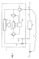
- FIG. 1 shows a schematic overview of a feedback compensator 1, which is a good quality reinforcement an acoustic input signal 3 with a hearing aid signal processing 5 also enables if a feedback path 7 is present, the frequency range of which varies due to external conditions can change.
- the feedback path 7 is for example by the diameter and by the Location of the ventilation ventilation hole of an in-the-ear hearing aid as well as a changing inadequate degree of the in-the-ear hearing aid with the ear. changes of the feedback path 7 also occur when the acoustic Environment changes, e.g. when a helmet is on or off becomes.
- the feedback compensator 1 is characterized in that he the frequency range of the compensation signal 8 to the adapt the changing frequency range of the feedback path 7 can.
- the feedback compensator 1 generates the compensation signal 8 as follows.
- a small part of the output signal 11 of the hearing aid signal processing 5 is on one Node 12 separated for the feedback compensator 1.
- There it is restricted with a filter 13 in the frequency range and an FIR filter 15. This generates from the filtered signal by means of its filter function, the compensation signal 8.
- the filter function of the FIR filter 15 is set by means of filter coefficients 16, which are generated by an adaptation unit 17 are transmitted to the FIR filter 15. Compare for adaptation the adaptation unit 17 an error signal 19 that the Input signal 3 after merging with the compensation signal 8 comes from, and that filtered with the filter 13 Output signal 11. Both signals are each with a filter 21 or 23 further restricted in the frequency domain.
- By change the coefficient 16 of the FIR filter 15 tries the Adaptation unit 17 to prevent feedback.
- the one filtered with the filter 13 Output signal 11 normalized signal energy of the error signal 19.
- the coefficients 16 of the FIR filter 15 are changed so that the signal energy of the error signal 19 minimal, i.e. is free of feedback.
- the Filters 13, 21 and 23 are adaptable in their filter function.
- the adaptation takes place via the filter coefficients of the filters, which are set by an analysis and control unit 25.
- the analysis and control unit 25 is with the adaptation unit 17 for information exchange about e.g. the filter coefficients 16 of the FIR filter 15 connected.
- a comparison of the Coefficients 16 with the coefficient or filter functions of the three filters 13, 21 and 23 allows the analysis and Control unit 25, the three filters 13, 21 and 23 such in their Adjust the filter function so that it works optimally with the Overlay the filter function of the FIR filter 15.
- the analysis and Control unit 25 then informs the adaptation unit 17 about the adaptation step size and adaptation speed, which on best to those set by the three filters 13, 21 and 23 Frequency ranges fit.
- FIG. 2 illustrates the operation of the adaptation of the filter function using coefficients using the example of filter 13.
- the amplitude of the feedback path 7 is plotted as a function from frequency on the one hand in the case of feedback in a narrow frequency range (feedback amplitude 27) and secondly in the event of a change in the acoustic environment leading to a feedback risk in one leads to a larger frequency range (feedback amplitude 29).
- the transmission of the filter 13 is also located.
- the transmission curve 31 for the first case is centered around 2kHz. The transmission drops to lower ones Frequencies drop sharply according to the feedback amplitude, so that only above 1kHz signal energy for feedback compensation is forwarded to the FIR filter 15.
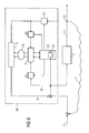
- FIG. 3 shows a schematic overview of a feedback compensator 39, which is essentially under construction and in its operation with the feedback compensator 1 in Figure 1 matches.
- the key difference is in the implementation of filters 13, 21 and 23 and in the adaptation their filter functions to limit the frequency range the feedback compensation.
- Filters 13, 21 and 23 each include a filter set 41, 43 and 45 and a switch 47, 49 and 51.
- the filters of the Filter sets 41, 43 and 45 cover those relevant for the feedback Frequency range.
- the adaptation of the filter functions is done by switching between the different filters of filter sets 41, 43 and 45 to switch or by the combined Use a selection of filters to determine how they work to add.
- the switches 47, 49 and 51 are of the Analysis and control unit 25 controlled.
- control unit 25 compares the different ones as in FIG Filter functions with the coefficients of the FIR filter 15 and adapts the filter functions of the three filters 13, 21 and 23 as best as possible to the filter function of the FIR filter 15.
- the feedback compensator 39 has compared to the feedback compensator 1 the advantage that the implementation of the filter 13, 21 and 23 using the switches 47, 49 and 51 and the preset filters of filter sets 41, 43 and 45 is simpler, saves space and energy.
- the filter functions in their course cannot be adjusted as precisely as with the feedback compensator 1 of Figure 1 is possible.
- FIG. 4 shows a possible division of the feedback-relevant Frequency range between 0.5kHz and 6kHz on the filters of a filter set using the example of the four filters 53, 55, 57 and 59 of the filter set 41.
- the transmission areas the filters 53, 55, 57 and 59 extend from different ones lower limit frequencies up to the common Upper limit of 6kHz.
- the use of the filter 57 is sufficient.
- the analysis detects and Control unit 25 this widening and controls the switch 47 so that the filter 53 for frequency limitation is used.
- FIG. 5 shows an alternative division of the frequency range with the filters 53, 55, 57 and 59, which in this case is narrow-band Filters are.
- the transmission ranges of the filters 53, 55, 57 and 59 together cover the one relevant for the feedback Frequency range.
- the transmission areas overlap in the peripheral areas.
- the feedback amplitude is 27 adequately compensated for by using filters 53 and 55, while for the feedback amplitude 29 all four Filters 53, 55, 57 and 59 used by the switch 47 at the same time become.
- FIG. 6 shows a feedback compensator 65, its functionality and mode of operation essentially again those of the feedback compensators 1 and 39 of FIG. 1 and 3 correspond.
- the analysis and control unit 25 additionally has an oscillation detector 67 which is connected to the input signal connected after the supply of the compensation signal 8 is.
- the oscillation detector 67 examines the input signal 3 on oscillations that dominate the input signal 3 and an indication of a feedback risk outside of the covered frequency range. Has the analysis and Control unit 25 using the oscillation detector 67 If a new feedback frequency is recognized, the filter function the filters 13, 21 and 23 to this new frequency range extended.
- the advantage of this embodiment is in the fact that it is usually already on an existing hearing aid Oscillation detector can be used. This simplifies it the implementation of the feedback compensator 65.
- FIG. 7 shows a schematic structure of a further exemplary embodiment shown for a feedback compensator.
- the feedback compensator 71 essentially results from the combination of the feedback compensators 39 from FIG 3 and 65 from Figure 6.
- This particularly advantageous embodiment combines the easy to implement Switching device between different filters and the use of an already existing oscillation detector to analyze the feedback. Again, with help the frequency range adaptation of the filters 13, 21 and 23 the quality and speed of the adaptation process for adjustment the filter function of the FIR filter 15 can be increased.
Landscapes
- Health & Medical Sciences (AREA)
- General Health & Medical Sciences (AREA)
- Neurosurgery (AREA)
- Otolaryngology (AREA)
- Physics & Mathematics (AREA)
- Engineering & Computer Science (AREA)
- Acoustics & Sound (AREA)
- Signal Processing (AREA)
- Tone Control, Compression And Expansion, Limiting Amplitude (AREA)
- Amplifiers (AREA)
- Circuit For Audible Band Transducer (AREA)
Abstract
Description
In einer Weiterbildung werden mittels einer Signalanalyse Parameter des adaptiven Rückkopplungskompensationsfilters mit dem Frequenzbereich, in dem die Rückkopplungspfadnachbildung stattfindet, verglichen. Dadurch erhält man wichtige Information darüber, ob der Frequenzbereich des Rückkopplungssignals mit dem Frequenzbereich, der vom Rückkopplungskompensationsfilter benötigt wird, übereinstimmt oder ob eine Adaption des Frequenzbereichs notwendig ist.
Claims (43)
- Rückkopplungskompensator (1, 39, 65, 71) in einem akustischen Verstärkungssystem zur Kompensation eines Rückkopplungssignals, das bei einer Verstärkung eines Eingangssignals (3) aufgrund eines Rückkopplungspfads (7) von einem verstärkten Ausgangssignal (11) auf das Eingangssignal (3) entsteht, mit einem adaptiven Rückkopplungskompensationsfilter (15), der ausgehend vom verstärkten Ausgangssignal (11) ein Kompensationssignal (8) erzeugt, und mit einem ersten Filter (13), der den Frequenzbereich begrenzt, in dem das Kompensationssignal (8) erzeugt wird,
dadurch gekennzeichnet, dass der erste Filter (13) in seiner Filterfunktion während des Betriebs des Rückkopplungskompensators (1, 39, 65, 71) adaptierbar ist. - Rückkopplungskompensator (1, 39, 65, 71) nach Anspruch 1,
dadurch gekennzeichnet, dass der erste Filter (13) aus mehreren Einzelfiltern besteht, deren Filterfunktionen gemeinsam die Filterfunktion des ersten Filters (13) bestimmen. - Rückkopplungskompensator (1, 39, 65, 71) nach Anspruch 2,
dadurch gekennzeichnet, dass zur Adaption der Filterfunktion mindestens einer der Einzelfilter aus einer Auswahl von Einzelfiltern mit unterschiedlichen Filterfunktionen wählbar ist. - Rückkopplungskompensator (1, 39, 65, 71) nach Anspruch 2 oder 3,
dadurch gekennzeichnet, dass die kumulierte Filterfunktion aller Einzelfilter den zur Rückkopplung relevanten Frequenzbereich abdeckt. - Rückkopplungskompensator (1, 39, 65, 71) nach einem der Ansprüche 1 bis 4,
dadurch gekennzeichnet, dass die Filterfunktion des ersten Filters (13) mittels Koeffizienten veränderbar ist. - Rückkopplungskompensator (1, 39, 65, 71) nach einem der Ansprüche 1 bis 5,
dadurch gekennzeichnet, dass das verstärkte Ausgangssignal über den ersten Filter (13) mit dem Rückkopplungskompensationsfilter (15) verbunden ist. - Rückkopplungskompensator (1, 39, 65, 71) nach einem der Ansprüche 1 bis 6,
dadurch gekennzeichnet, dass zusätzlich eine Steuereinheit (25) zur Adaption des ersten Filters (13) vorhanden ist. - Rückkopplungskompensator (1, 39, 65, 71) nach Anspruch 7,
dadurch gekennzeichnet, dass die Steuereinheit (25) mit einem Umschalter (47) zur Auswahl der Einzelfilter verbunden ist. - Rückkopplungskompensator (1, 39, 65, 71) nach Anspruch 7 oder 8,
dadurch gekennzeichnet, dass die Steuereinheit (25) Mittel zur Einstellung von Filterkoeffizienten aufweist. - Rückkopplungskompensator (1, 39, 65, 71) nach einem der Ansprüche 1 bis 9,
dadurch gekennzeichnet, dass zusätzlich eine Analyseeinheit (25) zur Überprüfung der Rückkopplungskompensation vorhanden ist. - Rückkopplungskompensator (1, 39, 65, 71) nach Anspruch 10, dadurch gekennzeichnet, dass die Analyseeinheit (25) Mittel zur Überprüfung der Parameter des adaptiven Rückkopplungskompensationsfilters (15) aufweist.
- Rückkopplungskompensator (1, 39, 65, 71) nach Anspruch 10 oder 11,
dadurch gekennzeichnet, dass die Analyseeinheit (25) Mittel zum Vergleichen des Eingangssignals (3) mit Ausgangssignal (11) in Hinblick auf Rückkopplung aufweist. - Rückkopplungskompensator (1, 39, 65, 71) nach einem der Ansprüche 10 bis 12,
dadurch gekennzeichnet, dass die Analyseeinheit (25) einen Oszillationsdetektor (67) zur Messung von Rückkopplung im verstärkten Frequenzbereich umfasst. - Rückkopplungskompensator (1, 39, 65, 71) nach einem der Ansprüche 1 bis 13,
dadurch gekennzeichnet, dass der Rückkopplungspfad (7) ein akustischer Rückkopplungspfad ist. - Rückkopplungskompensator (1, 39, 65, 71) nach einem der Ansprüche 1 bis 14,
dadurch gekennzeichnet, dass der Rückkopplungspfad (7) ein elektromagnetischer Rückkopplungspfad ist. - Rückkopplungskompensator (1, 39, 65, 71) nach einem der Ansprüche 1 bis 15,
dadurch gekennzeichnet, dass der adaptive Rückkopplungskompensationsfilter (15) eine Adaptionseinheit (17) aufweist. - Rückkopplungskompensator (1, 39, 65, 71) nach Anspruch 16, dadurch gekennzeichnet, dass die Adaptionseinheit (17) zur Fehlersignalauswertung mit dem Eingangssignal (3) verbunden ist.
- Rückkopplungskompensator (1, 39, 65, 71) nach Anspruch 17, dadurch gekennzeichnet, dass die Verbindung der Adaptionseinheit (17) mit dem Eingangssignal (3) einen zweiten Filter (21) aufweist.
- Rückkopplungskompensator (1, 39, 65, 71) nach einem der Ansprüche 16 bis 18,
dadurch gekennzeichnet, dass die Adaptionseinheit (17) mit dem Ausgang des ersten Filters (13) verbunden ist. - Rückkopplungskompensator (1, 39, 65, 71) nach Anspruch 19, dadurch gekennzeichnet, dass die Verbindung der Adaptionseinheit (17) mit dem ersten Filter (13) einen dritten Filter (23) aufweist.
- Rückkopplungskompensator (1, 39, 65, 71) nach Anspruch 20, dadurch gekennzeichnet, dass die Filterfunktion des dritten Filters (23) zumindest im wesentlichen gleich der Filterfunktion des zweiten Filters (21) ist.
- Rückkopplungskompensator (1, 39, 65, 71) nach einem der Ansprüche 18 bis 21,
dadurch gekennzeichnet, dass der zweite und/oder der dritte Filter (21, 23) in ihrer Filterfunktion adaptierbare Filter sind. - Rückkopplungskompensator (1, 39, 65, 71) nach Anspruch 22, dadurch gekennzeichnet, dass die Steuereinheit (25) Mittel zur Adaption des zweiten und/oder dritten Filters (21, 23) aufweist.
- Rückkopplungskompensator (1, 39, 65, 71) nach Anspruch 23, dadurch gekennzeichnet, dass die Steuereinheit (25) mit einem Umschalter (49, 51) zur Auswahl der Einzelfilter verbunden ist.
- Rückkopplungskompensator (1, 39, 65, 71) nach Anspruch 23 oder 24,
dadurch gekennzeichnet, dass die Steuereinheit (25) Mittel zur Einstellung von Filterkoeffizienten aufweist. - Hörhilfsgerät mit einem Rückkopplungskompensator (1, 39, 65, 71) nach einem der Ansprüche 1 bis 25.
- Verfahren zur Kompensation eines Rückkopplungssignals in einem akustischen System, wobei das Rückkopplungssignal bei einer Verstärkung eines Eingangssignals (3) aufgrund eines Rückkopplungspfads (7) von einem verstärkten Ausgangssignal (11) auf das Eingangssignal (3) entsteht, und wobei ein adaptiver Rückkopplungskompensationsfilter (15) zur Nachbildung des Rückkopplungssignals ein Kompensationssignal (8) ausgehend vom verstärkten Ausgangssignal (11) erzeugt,
dadurch gekennzeichnet, dass der Frequenzbereich, in dem das Kompensationssignal (8) erzeugt wird, während der Kompensation adaptiert wird. - Verfahren nach Anspruch 27,
dadurch gekennzeichnet, dass zur Frequenzbereichsadaption zwischen mehreren parallel vorhandenen Filtern oder Filtersätzen (41) umgeschaltet wird. - Verfahren nach Anspruch 27 oder 28,
dadurch gekennzeichnet, dass die Frequenzbereichsadaption mit einem in seiner Filterfunktion veränderbaren ersten Filter (13) durchgeführt wird. - Verfahren nach einem der Ansprüche 27 bis 29,
dadurch gekennzeichnet, dass die Filterfunktion des ersten Filters (13) mittels Koeffizienten verändert wird. - Verfahren nach einem der Ansprüche 27 bis 30,
dadurch gekennzeichnet, dass mittels einer Signalanalyse die Rückkopplungskompensation überprüft wird. - Verfahren nach Anspruch 31,
dadurch gekennzeichnet, dass mittels einer Signalanalyse Parameter des adaptiven Rückkopplungskompensationsfilters (15) mit dem Frequenzbereich, in dem die Rückkopplungspfadnachbildung stattfindet, verglichen wird. - Verfahren nach einem der Ansprüche 27 bis 32,
dadurch gekennzeichnet, dass mittels der Frequenzbereichsadaption der Frequenzbereich des Rückkopplungskompensationsfilters (15) auf den Frequenzbereich, in dem die Rückkopplungspfadnachbildung stattfindet, abgestimmt wird. - Verfahren nach einem der Ansprüche 31 bis 33,
dadurch gekennzeichnet, dass mittels einer Signalanalyse das Eingangssignal (3) auf Rückkopplungssignalanteile überprüft wird. - Verfahren nach einem der Ansprüche 31 bis 34,
dadurch gekennzeichnet, dass mittels einer Signalanalyse zur Erkennung von Rückkopplung im verstärkten Frequenzbereich Oszillationen im Eingangssignal (3) detektiert werden und dass erkannte Rückkopplungen mithilfe der Frequenzbereichsadaption kompensiert werden. - Verfahren nach einem der Ansprüche 27 bis 35,
dadurch gekennzeichnet, dass mittels einer Adaptionseinheit (17) der Rückkopplungskompensationsfilters (15) adaptiert wird. - Verfahren nach Anspruch 36,
dadurch gekennzeichnet, dass mittels der Adaptionseinheit (17) Koeffizienten (16) des Rückkopplungskompensationsfilters (15) eingestellt werden. - Verfahren nach Anspruch 36 oder 37,
dadurch gekennzeichnet, dass während der Adaption ein mit einem zweiten Filter (21) gefiltertes Fehlersignal (19) mit dem Signal zur Nachbildung des Rückkopplungspfads verglichen wird. - Verfahren nach Anspruch 38,
dadurch gekennzeichnet, dass das Signal zur Nachbildung des Rückkopplungspfads vor dem Vergleich mit einem dritten Filter (23) gefiltert wird. - Verfahren nach Anspruch 38 oder 39,
dadurch gekennzeichnet, dass die Filterfunktionen des zweiten und/oder dritten Filters (21, 23) adaptiert werden. - Verfahren nach Anspruch 40,
dadurch gekennzeichnet, dass zur Adaption die Filterfunktion des zweiten und/oder dritten Filters (21, 23) mittels eines Umschalters (49, 51) aus einer Auswahl von Einzelfiltern gewählt werden. - Verfahren nach Anspruch 40,
dadurch gekennzeichnet, dass zur Adaption des zweiten und/oder dritten Filters (21, 23) ihre Filterfunktionen mittels Filterkoeffizienten eingestellt werden. - Anwendung des Verfahrens nach einem der Ansprüche 27 bis 42 in einem Hörhilfsgerät.
Applications Claiming Priority (2)
| Application Number | Priority Date | Filing Date | Title |
|---|---|---|---|
| DE10242700 | 2002-09-13 | ||
| DE10242700A DE10242700B4 (de) | 2002-09-13 | 2002-09-13 | Rückkopplungskompensator in einem akustischen Verstärkungssystem, Hörhilfsgerät, Verfahren zur Rückkopplungskompensation und Anwendung des Verfahrens in einem Hörhilfsgerät |
Publications (3)
| Publication Number | Publication Date |
|---|---|
| EP1398993A2 true EP1398993A2 (de) | 2004-03-17 |
| EP1398993A3 EP1398993A3 (de) | 2009-03-25 |
| EP1398993B1 EP1398993B1 (de) | 2011-08-17 |
Family
ID=31724752
Family Applications (1)
| Application Number | Title | Priority Date | Filing Date |
|---|---|---|---|
| EP03019877A Revoked EP1398993B1 (de) | 2002-09-13 | 2003-09-01 | Vorrichtung und Verfahren zur Rückkopplungskompensation in einem akustischen Verstärkungssystem, insbesondere in einem Hörgerät |
Country Status (5)
| Country | Link |
|---|---|
| US (2) | US20040125966A1 (de) |
| EP (1) | EP1398993B1 (de) |
| AT (1) | ATE521197T1 (de) |
| DE (1) | DE10242700B4 (de) |
| DK (1) | DK1398993T3 (de) |
Cited By (1)
| Publication number | Priority date | Publication date | Assignee | Title |
|---|---|---|---|---|
| WO2010040863A2 (en) | 2010-01-15 | 2010-04-15 | Phonak Ag | A method for operating a hearing device as well as a hearing device |
Families Citing this family (11)
| Publication number | Priority date | Publication date | Assignee | Title |
|---|---|---|---|---|
| US6876751B1 (en) * | 1998-09-30 | 2005-04-05 | House Ear Institute | Band-limited adaptive feedback canceller for hearing aids |
| DK2986033T3 (da) * | 2005-03-29 | 2020-11-23 | Oticon As | Høreapparat til registrering af data og læring der fra |
| JP4860712B2 (ja) * | 2006-03-09 | 2012-01-25 | ヴェーデクス・アクティーセルスカプ | 適応フィードバック抑制を伴う補聴器 |
| US8280088B2 (en) * | 2006-05-19 | 2012-10-02 | Siemens Audiologische Technik Gmbh | Hearing apparatus with feedback detection and corresponding method |
| US9271090B2 (en) * | 2007-12-07 | 2016-02-23 | Wolfson Dynamic Hearing Pty Ltd | Entrainment resistant feedback cancellation |
| WO2009124550A1 (en) * | 2008-04-10 | 2009-10-15 | Gn Resound A/S | An audio system with feedback cancellation |
| US8358797B2 (en) * | 2008-08-12 | 2013-01-22 | Intricon Corporation | Switch for a hearing aid |
| US8767987B2 (en) * | 2008-08-12 | 2014-07-01 | Intricon Corporation | Ear contact pressure wave hearing aid switch |
| DE102009014540A1 (de) * | 2009-03-24 | 2010-10-07 | Siemens Medical Instruments Pte. Ltd. | Verfahren zum Betreiben einer Hörvorrichtung mit verstärkter Rückkopplungskompensation und Hörvorrichtung |
| DE102009031135A1 (de) * | 2009-06-30 | 2011-01-27 | Siemens Medical Instruments Pte. Ltd. | Hörvorrichtung und Verfahren zur Unterdrückung von Rückkopplungen |
| US9351085B2 (en) | 2012-12-20 | 2016-05-24 | Cochlear Limited | Frequency based feedback control |
Family Cites Families (16)
| Publication number | Priority date | Publication date | Assignee | Title |
|---|---|---|---|---|
| US4689818A (en) * | 1983-04-28 | 1987-08-25 | Siemens Hearing Instruments, Inc. | Resonant peak control |
| US5717772A (en) * | 1995-08-07 | 1998-02-10 | Motorola, Inc. | Method and apparatus for suppressing acoustic feedback in an audio system |
| US6072884A (en) * | 1997-11-18 | 2000-06-06 | Audiologic Hearing Systems Lp | Feedback cancellation apparatus and methods |
| DE19635878A1 (de) * | 1996-09-04 | 1998-03-05 | Deutsche Telekom Ag | Vorrichtung zur Verbesserung des Sendesignals einer Echoreduktionseinrichtung |
| DE19639580C2 (de) * | 1996-09-26 | 1998-09-17 | Deutsche Telekom Ag | Vorrichtung zur Reduktion akustischer Echos |
| DE19714966C2 (de) * | 1997-04-10 | 1999-04-01 | Siemens Ag | Vorrichtung zur Rückhördämpfung |
| JPH11127496A (ja) * | 1997-10-20 | 1999-05-11 | Sony Corp | ハウリング除去装置 |
| DE19805942C1 (de) * | 1998-02-13 | 1999-08-12 | Siemens Ag | Verfahren zur Verbesserung der akustischen Rückhördämpfung in Freisprecheinrichtungen |
| US6876751B1 (en) * | 1998-09-30 | 2005-04-05 | House Ear Institute | Band-limited adaptive feedback canceller for hearing aids |
| WO2000019605A2 (en) * | 1998-09-30 | 2000-04-06 | House Ear Institute | Band-limited adaptive feedback canceller for hearing aids |
| DE19904538C1 (de) * | 1999-02-04 | 2000-07-13 | Siemens Audiologische Technik | Verfahren zur Rückkopplungserkennung in einem Hörgerät und Hörgerät |
| US6434247B1 (en) * | 1999-07-30 | 2002-08-13 | Gn Resound A/S | Feedback cancellation apparatus and methods utilizing adaptive reference filter mechanisms |
| EP1119218B1 (de) * | 2000-01-21 | 2018-06-20 | Oticon A/S | Elektromagnetische Rückkopplungsverminderung in einem Kommunikationsgerät |
| EP1191813A1 (de) * | 2000-09-25 | 2002-03-27 | TOPHOLM & WESTERMANN APS | Hörgerät mit adaptivem Filter zur Unterdrückung akustischer Rückkopplung |
| EP2066139A3 (de) * | 2000-09-25 | 2010-06-23 | Widex A/S | Hörgerät |
| US6831986B2 (en) * | 2000-12-21 | 2004-12-14 | Gn Resound A/S | Feedback cancellation in a hearing aid with reduced sensitivity to low-frequency tonal inputs |
-
2002
- 2002-09-13 DE DE10242700A patent/DE10242700B4/de not_active Expired - Fee Related
-
2003
- 2003-09-01 DK DK03019877.4T patent/DK1398993T3/da active
- 2003-09-01 AT AT03019877T patent/ATE521197T1/de active
- 2003-09-01 EP EP03019877A patent/EP1398993B1/de not_active Revoked
- 2003-09-10 US US10/659,230 patent/US20040125966A1/en not_active Abandoned
-
2008
- 2008-02-08 US US12/028,259 patent/US20080123885A1/en not_active Abandoned
Cited By (1)
| Publication number | Priority date | Publication date | Assignee | Title |
|---|---|---|---|---|
| WO2010040863A2 (en) | 2010-01-15 | 2010-04-15 | Phonak Ag | A method for operating a hearing device as well as a hearing device |
Also Published As
| Publication number | Publication date |
|---|---|
| US20040125966A1 (en) | 2004-07-01 |
| EP1398993A3 (de) | 2009-03-25 |
| EP1398993B1 (de) | 2011-08-17 |
| US20080123885A1 (en) | 2008-05-29 |
| ATE521197T1 (de) | 2011-09-15 |
| DE10242700B4 (de) | 2006-08-03 |
| DK1398993T3 (da) | 2011-12-05 |
| DE10242700A1 (de) | 2004-05-06 |
Similar Documents
| Publication | Publication Date | Title |
|---|---|---|
| EP2180726B1 (de) | Richtungshören bei binauraler Hörgeräteversorgung | |
| EP0071845B1 (de) | Gerät zur Kompensation von Gehörschäden | |
| EP1366564B1 (de) | Vorrichtung zum geräuschabhängigen einstellen der lautstärken | |
| EP1853089B2 (de) | Verfahren zum Unterdrücken von Rückkopplungen und zur Spektralerweiterung bei Hörvorrichtungen | |
| DE69627612T2 (de) | Frequenzselektiver aktiver adaptiver Steuerungsanordnung | |
| DE102005020317B4 (de) | Automatische Verstärkungseinstellung bei einem Hörhilfegerät | |
| EP1912471B1 (de) | Verarbeitung eines Eingangssignals in einer Hörhilfe | |
| EP2244491B2 (de) | Verfahren zum Betrieb einer Hörvorrichtung und Hörvorrichtung mit einer Frequenzweiche | |
| EP1360870A2 (de) | Verfahren zum betrieb eines hörgerätesystems sowie hörgerätesystem | |
| DE102006047965A1 (de) | Hörhilfsgerät mit einer Okklusionsreduktionseinrichtung und Verfahren zur Okklusionsreduktion | |
| DE10242700B4 (de) | Rückkopplungskompensator in einem akustischen Verstärkungssystem, Hörhilfsgerät, Verfahren zur Rückkopplungskompensation und Anwendung des Verfahrens in einem Hörhilfsgerät | |
| CH694543A5 (de) | Verfahren zur Rückkopplungserkennung in einem Hörgerät und Hörgerät zum Ausführen dieses Verfahrens. | |
| EP2081406A1 (de) | Verfahren und Vorrichtung zur Konfiguration von Einstellmöglichkeiten an einem Hörgerät | |
| DE10244184B3 (de) | Feedbackkompensation für Hörgeräte mit Systemabstandsschätzung | |
| DE102019213810B3 (de) | Verfahren zum Betrieb eines Hörgeräts und Hörgerät | |
| EP1542500B1 (de) | Hörgerät mit Störgeräuschunterdrückung und entsprechendes Störgeräuschunterdrückungsverfahren | |
| EP1367856A2 (de) | Vorrichtung und Verfahren zur Feedbackreduktion bei Hörsystemen | |
| DE10245667B4 (de) | Rückkopplungkompensator in einem akustischen Verstärkungssystem, Hörhilfsgerät, Verfahren zur Rückkopplungskompensation und Anwendung des Verfahrens in einem Hörhilfsgerät | |
| EP3355592B1 (de) | Verfahren zum betrieb eines binauralen hörgerätesystems | |
| EP4274260A1 (de) | Verfahren zum betrieb eines hörgerätes und hörgerät | |
| EP1648197B2 (de) | Verfahren und Vorrichtung zur Reduktion von Rückkopplungen bei einem Akustiksystem | |
| EP1858289A1 (de) | Hörvorrichtung mit Rückkopplungsdetektion und entsprechendes Verfahren | |
| DE10310580A1 (de) | Vorrichtung und Verfahren zur Adaption von Hörgerätemikrofonen | |
| EP1303166A2 (de) | Verfahren zum Betrieb eines Hörgerätes und Anordung mit einem Hörgerät | |
| DE10321625A1 (de) | Signalübertragungsvorrichtung |
Legal Events
| Date | Code | Title | Description |
|---|---|---|---|
| PUAI | Public reference made under article 153(3) epc to a published international application that has entered the european phase |
Free format text: ORIGINAL CODE: 0009012 |
|
| AK | Designated contracting states |
Kind code of ref document: A2 Designated state(s): AT BE BG CH CY CZ DE DK EE ES FI FR GB GR HU IE IT LI LU MC NL PT RO SE SI SK TR |
|
| AX | Request for extension of the european patent |
Extension state: AL LT LV MK |
|
| PUAL | Search report despatched |
Free format text: ORIGINAL CODE: 0009013 |
|
| AK | Designated contracting states |
Kind code of ref document: A3 Designated state(s): AT BE BG CH CY CZ DE DK EE ES FI FR GB GR HU IE IT LI LU MC NL PT RO SE SI SK TR |
|
| AX | Request for extension of the european patent |
Extension state: AL LT LV MK |
|
| 17P | Request for examination filed |
Effective date: 20090309 |
|
| AKX | Designation fees paid |
Designated state(s): AT BE BG CH CY CZ DE DK EE ES FI FR GB GR HU IE IT LI LU MC NL PT RO SE SI SK TR |
|
| GRAP | Despatch of communication of intention to grant a patent |
Free format text: ORIGINAL CODE: EPIDOSNIGR1 |
|
| RTI1 | Title (correction) |
Free format text: APPARATUS AND METHOD FOR FEEDBACK COMPENSATION IN AN ACOUSTIC AMPLIFICATION SYSTEM, ESPECIALLY IN A HEARING AID |
|
| GRAS | Grant fee paid |
Free format text: ORIGINAL CODE: EPIDOSNIGR3 |
|
| GRAA | (expected) grant |
Free format text: ORIGINAL CODE: 0009210 |
|
| AK | Designated contracting states |
Kind code of ref document: B1 Designated state(s): AT BE BG CH CY CZ DE DK EE ES FI FR GB GR HU IE IT LI LU MC NL PT RO SE SI SK TR |
|
| REG | Reference to a national code |
Ref country code: GB Ref legal event code: FG4D Free format text: NOT ENGLISH |
|
| REG | Reference to a national code |
Ref country code: CH Ref legal event code: EP Ref country code: CH Ref legal event code: NV Representative=s name: SIEMENS SCHWEIZ AG |
|
| REG | Reference to a national code |
Ref country code: IE Ref legal event code: FG4D Free format text: LANGUAGE OF EP DOCUMENT: GERMAN |
|
| REG | Reference to a national code |
Ref country code: DE Ref legal event code: R096 Ref document number: 50313906 Country of ref document: DE Effective date: 20111020 |
|
| PGFP | Annual fee paid to national office [announced via postgrant information from national office to epo] |
Ref country code: DK Payment date: 20110926 Year of fee payment: 9 |
|
| PGFP | Annual fee paid to national office [announced via postgrant information from national office to epo] |
Ref country code: GB Payment date: 20110915 Year of fee payment: 9 Ref country code: FR Payment date: 20111005 Year of fee payment: 9 |
|
| REG | Reference to a national code |
Ref country code: DK Ref legal event code: T3 |
|
| REG | Reference to a national code |
Ref country code: NL Ref legal event code: VDEP Effective date: 20110817 |
|
| PG25 | Lapsed in a contracting state [announced via postgrant information from national office to epo] |
Ref country code: SE Free format text: LAPSE BECAUSE OF FAILURE TO SUBMIT A TRANSLATION OF THE DESCRIPTION OR TO PAY THE FEE WITHIN THE PRESCRIBED TIME-LIMIT Effective date: 20110817 Ref country code: PT Free format text: LAPSE BECAUSE OF FAILURE TO SUBMIT A TRANSLATION OF THE DESCRIPTION OR TO PAY THE FEE WITHIN THE PRESCRIBED TIME-LIMIT Effective date: 20111219 Ref country code: FI Free format text: LAPSE BECAUSE OF FAILURE TO SUBMIT A TRANSLATION OF THE DESCRIPTION OR TO PAY THE FEE WITHIN THE PRESCRIBED TIME-LIMIT Effective date: 20110817 Ref country code: NL Free format text: LAPSE BECAUSE OF FAILURE TO SUBMIT A TRANSLATION OF THE DESCRIPTION OR TO PAY THE FEE WITHIN THE PRESCRIBED TIME-LIMIT Effective date: 20110817 |
|
| PGFP | Annual fee paid to national office [announced via postgrant information from national office to epo] |
Ref country code: CH Payment date: 20111213 Year of fee payment: 9 |
|
| PG25 | Lapsed in a contracting state [announced via postgrant information from national office to epo] |
Ref country code: CY Free format text: LAPSE BECAUSE OF FAILURE TO SUBMIT A TRANSLATION OF THE DESCRIPTION OR TO PAY THE FEE WITHIN THE PRESCRIBED TIME-LIMIT Effective date: 20110817 Ref country code: SI Free format text: LAPSE BECAUSE OF FAILURE TO SUBMIT A TRANSLATION OF THE DESCRIPTION OR TO PAY THE FEE WITHIN THE PRESCRIBED TIME-LIMIT Effective date: 20110817 Ref country code: GR Free format text: LAPSE BECAUSE OF FAILURE TO SUBMIT A TRANSLATION OF THE DESCRIPTION OR TO PAY THE FEE WITHIN THE PRESCRIBED TIME-LIMIT Effective date: 20111118 |
|
| REG | Reference to a national code |
Ref country code: IE Ref legal event code: FD4D |
|
| BERE | Be: lapsed |
Owner name: SIEMENS AUDIOLOGISCHE TECHNIK G.M.B.H. Effective date: 20110930 |
|
| PG25 | Lapsed in a contracting state [announced via postgrant information from national office to epo] |
Ref country code: IE Free format text: LAPSE BECAUSE OF FAILURE TO SUBMIT A TRANSLATION OF THE DESCRIPTION OR TO PAY THE FEE WITHIN THE PRESCRIBED TIME-LIMIT Effective date: 20110817 Ref country code: SK Free format text: LAPSE BECAUSE OF FAILURE TO SUBMIT A TRANSLATION OF THE DESCRIPTION OR TO PAY THE FEE WITHIN THE PRESCRIBED TIME-LIMIT Effective date: 20110817 Ref country code: MC Free format text: LAPSE BECAUSE OF NON-PAYMENT OF DUE FEES Effective date: 20110930 Ref country code: CZ Free format text: LAPSE BECAUSE OF FAILURE TO SUBMIT A TRANSLATION OF THE DESCRIPTION OR TO PAY THE FEE WITHIN THE PRESCRIBED TIME-LIMIT Effective date: 20110817 |
|
| PLBI | Opposition filed |
Free format text: ORIGINAL CODE: 0009260 |
|
| PG25 | Lapsed in a contracting state [announced via postgrant information from national office to epo] |
Ref country code: EE Free format text: LAPSE BECAUSE OF FAILURE TO SUBMIT A TRANSLATION OF THE DESCRIPTION OR TO PAY THE FEE WITHIN THE PRESCRIBED TIME-LIMIT Effective date: 20110817 Ref country code: RO Free format text: LAPSE BECAUSE OF FAILURE TO SUBMIT A TRANSLATION OF THE DESCRIPTION OR TO PAY THE FEE WITHIN THE PRESCRIBED TIME-LIMIT Effective date: 20110817 Ref country code: IT Free format text: LAPSE BECAUSE OF FAILURE TO SUBMIT A TRANSLATION OF THE DESCRIPTION OR TO PAY THE FEE WITHIN THE PRESCRIBED TIME-LIMIT Effective date: 20110817 |
|
| PLAX | Notice of opposition and request to file observation + time limit sent |
Free format text: ORIGINAL CODE: EPIDOSNOBS2 |
|
| 26 | Opposition filed |
Opponent name: GN RESOUND A/S / WIDEX A/S / OTICON A/S Effective date: 20120516 |
|
| PG25 | Lapsed in a contracting state [announced via postgrant information from national office to epo] |
Ref country code: BE Free format text: LAPSE BECAUSE OF NON-PAYMENT OF DUE FEES Effective date: 20110930 |
|
| RDAF | Communication despatched that patent is revoked |
Free format text: ORIGINAL CODE: EPIDOSNREV1 |
|
| REG | Reference to a national code |
Ref country code: DE Ref legal event code: R103 Ref document number: 50313906 Country of ref document: DE Ref country code: DE Ref legal event code: R064 Ref document number: 50313906 Country of ref document: DE |
|
| REG | Reference to a national code |
Ref country code: DE Ref legal event code: R026 Ref document number: 50313906 Country of ref document: DE Effective date: 20120516 |
|
| RDAG | Patent revoked |
Free format text: ORIGINAL CODE: 0009271 |
|
| STAA | Information on the status of an ep patent application or granted ep patent |
Free format text: STATUS: PATENT REVOKED |
|
| REG | Reference to a national code |
Ref country code: CH Ref legal event code: PL |
|
| 27W | Patent revoked |
Effective date: 20120810 |
|
| GBPR | Gb: patent revoked under art. 102 of the ep convention designating the uk as contracting state |
Effective date: 20120810 |
|
| PG25 | Lapsed in a contracting state [announced via postgrant information from national office to epo] |
Ref country code: LI Free format text: LAPSE BECAUSE OF THE APPLICANT RENOUNCES Effective date: 20110817 Ref country code: CH Free format text: LAPSE BECAUSE OF THE APPLICANT RENOUNCES Effective date: 20110817 Ref country code: AT Free format text: LAPSE BECAUSE OF NON-PAYMENT OF DUE FEES Effective date: 20110901 |
|
| REG | Reference to a national code |
Ref country code: DE Ref legal event code: R107 Ref document number: 50313906 Country of ref document: DE Effective date: 20130207 |
|
| REG | Reference to a national code |
Ref country code: AT Ref legal event code: MA03 Ref document number: 521197 Country of ref document: AT Kind code of ref document: T Effective date: 20120810 |
|
| PG25 | Lapsed in a contracting state [announced via postgrant information from national office to epo] |
Ref country code: BG Free format text: LAPSE BECAUSE OF FAILURE TO SUBMIT A TRANSLATION OF THE DESCRIPTION OR TO PAY THE FEE WITHIN THE PRESCRIBED TIME-LIMIT Effective date: 20111117 |
|
| PG25 | Lapsed in a contracting state [announced via postgrant information from national office to epo] |
Ref country code: HU Free format text: LAPSE BECAUSE OF FAILURE TO SUBMIT A TRANSLATION OF THE DESCRIPTION OR TO PAY THE FEE WITHIN THE PRESCRIBED TIME-LIMIT Effective date: 20110817 |
|
| PG25 | Lapsed in a contracting state [announced via postgrant information from national office to epo] |
Ref country code: LU Free format text: LAPSE BECAUSE OF NON-PAYMENT OF DUE FEES Effective date: 20110901 |
|
| PG25 | Lapsed in a contracting state [announced via postgrant information from national office to epo] |
Ref country code: ES Free format text: LAPSE BECAUSE OF NON-PAYMENT OF DUE FEES Effective date: 20110902 |