EP1397789B1 - Vorrichtung und verfahren zum detektieren von brandherden oder gasverunreinigungen - Google Patents
Vorrichtung und verfahren zum detektieren von brandherden oder gasverunreinigungen Download PDFInfo
- Publication number
- EP1397789B1 EP1397789B1 EP02747322A EP02747322A EP1397789B1 EP 1397789 B1 EP1397789 B1 EP 1397789B1 EP 02747322 A EP02747322 A EP 02747322A EP 02747322 A EP02747322 A EP 02747322A EP 1397789 B1 EP1397789 B1 EP 1397789B1
- Authority
- EP
- European Patent Office
- Prior art keywords
- fire
- gas
- valves
- detector
- gas impurities
- Prior art date
- Legal status (The legal status is an assumption and is not a legal conclusion. Google has not performed a legal analysis and makes no representation as to the accuracy of the status listed.)
- Expired - Lifetime
Links
- 239000012535 impurity Substances 0.000 title claims abstract 17
- 238000000034 method Methods 0.000 title claims description 22
- 238000001514 detection method Methods 0.000 claims abstract description 27
- 238000012544 monitoring process Methods 0.000 claims abstract description 14
- 239000012080 ambient air Substances 0.000 claims abstract description 3
- 238000000605 extraction Methods 0.000 claims description 2
- 230000002123 temporal effect Effects 0.000 claims 1
- 230000004807 localization Effects 0.000 abstract description 13
- 239000000779 smoke Substances 0.000 description 12
- 239000000356 contaminant Substances 0.000 description 11
- 239000003570 air Substances 0.000 description 10
- 238000004891 communication Methods 0.000 description 6
- 238000009434 installation Methods 0.000 description 6
- 238000011109 contamination Methods 0.000 description 5
- 238000013461 design Methods 0.000 description 3
- 230000004913 activation Effects 0.000 description 2
- 238000003915 air pollution Methods 0.000 description 2
- 230000001419 dependent effect Effects 0.000 description 2
- 238000011161 development Methods 0.000 description 2
- 230000018109 developmental process Effects 0.000 description 2
- 239000000203 mixture Substances 0.000 description 2
- 230000003287 optical effect Effects 0.000 description 2
- 230000001154 acute effect Effects 0.000 description 1
- 239000000443 aerosol Substances 0.000 description 1
- 230000033228 biological regulation Effects 0.000 description 1
- 230000005540 biological transmission Effects 0.000 description 1
- 230000015572 biosynthetic process Effects 0.000 description 1
- 150000001875 compounds Chemical class 0.000 description 1
- 230000000694 effects Effects 0.000 description 1
- 230000005284 excitation Effects 0.000 description 1
- 239000007789 gas Substances 0.000 description 1
- 210000004907 gland Anatomy 0.000 description 1
- 244000144980 herd Species 0.000 description 1
- 239000007788 liquid Substances 0.000 description 1
- 239000011159 matrix material Substances 0.000 description 1
- 239000002245 particle Substances 0.000 description 1
- 230000005855 radiation Effects 0.000 description 1
- 238000005070 sampling Methods 0.000 description 1
- 239000007787 solid Substances 0.000 description 1
- 238000012546 transfer Methods 0.000 description 1
- 230000001960 triggered effect Effects 0.000 description 1
Images


Classifications
-
- G—PHYSICS
- G08—SIGNALLING
- G08B—SIGNALLING OR CALLING SYSTEMS; ORDER TELEGRAPHS; ALARM SYSTEMS
- G08B17/00—Fire alarms; Alarms responsive to explosion
- G08B17/10—Actuation by presence of smoke or gases, e.g. automatic alarm devices for analysing flowing fluid materials by the use of optical means
- G08B17/11—Actuation by presence of smoke or gases, e.g. automatic alarm devices for analysing flowing fluid materials by the use of optical means using an ionisation chamber for detecting smoke or gas
- G08B17/113—Constructional details
Definitions
- the invention relates to a device for detecting and locating fire pits or gas contaminants in one or more monitoring rooms, with a (main) detector for detecting a fire characteristic in which via a arranged in each monitoring room and provided with suction pipe by means of a suction constantly a subset the room air contained in the interstitial space is supplied, as well as a method for single detection of fire or gas contaminants in one or more monitoring rooms with a (main) detector, which is connected via a pipe and attached to this pipe suction with the interstitial space for continuous Removal and monitoring of gas samples from the interstitial space.
- the reporting area of a single monitored zone may not exceed 2000 m 2 . Further details are provided for the search distance, which must not be more than 30 m for the optical detection of a fire source within a zone by the emergency services. As a possible detection aid the use of alarm lamps in different places is recommended.
- fire characteristic physical quantities understood that are subject to measurable changes in the environment of a fire, eg. As the ambient temperature, the solids or liquid or gas content in the ambient air (formation of smoke particles or aerosols - or steam), or the ambient radiation.
- Detector boxes which serve to identify the smoke aspirating branch in a branched intake manifold system.
- This detector box consists of a point-shaped smoke detector with a cable gland installed in a housing for connecting the incoming and outgoing pipes and a beacon on the cover.
- a disadvantage of this embodiment is that these detector boxes can not be used at every single intake because of their size, their design and their price.
- the method uses and contains the corresponding device in each monitoring space two there intersecting pipes by means of which one or more fans continuously subsets of air contained in the interstitial space or gas mixture sucked through provided in the pipes suction and at least one detector for detecting a Fire characteristic or a gas contamination per pipe is supplied.
- the localization of the source of the fire or of the source of contamination takes place by a response of both detectors associated with the intersecting pipelines.
- German Patent DE 3 237 021 C2 is a selective gas / smoke detection system with a number of separately and connected to different measuring points in a room to be monitored suction lines for taking air or gas samples at these measuring points known.
- a gas or smoke detector which is connected to these lines, the presence of a certain gas in the sample when exceeding a set threshold value and outputs a detection signal that controls a display and / or alarm circuit.
- shutter valves which cyclically and periodically controlled by a control circuit are excitable.
- a fire detection by means of this gas / smoke detection system is such that the control unit in the absence of a detection signal, the shutter valves are set so that all intake ports are simultaneously in open communication with the Dektektor, and switches upon receipt of a detection signal in a scanning manner, in which the suction lines to usually one after the other or in groups in open communication with the detector.
- this mode of operation for detecting a source of fire presupposes that the detector can be connected to the respective premises to be monitored via individual and selectively openable supply lines.
- the disadvantage of this is also a fairly high installation cost for the necessary suction lines.
- a source of fire or a source of gas contaminants can be localized using the more or less charged with fire or gas indicators gas stream.
- a source of fire or a source of gas contaminants can be localized using the more or less charged with fire or gas indicators gas stream.
- a wireless, radio-based communication between transmitting and receiving module is provided, which e.g. ensures a particularly reliable control in case of fire.
- a lightwave-based communication e.g. in the infrared range or a communication in the ultrasonic range.
- the solenoid valves are provided in their simplest and least expensive form with a conical closure body and a matching molded seat. For flow reasons - to avoid too great Ansaugwiderêtn - but also a spherical closure body is possible, which ensures a minimum turbulence of the gas flow to the valve. Constructively, combinations of e.g. Conical closure body and spherical housing of the solenoid possible to exclude excessive throttle effect.
- valves are open at rest, so do not need to be activated first to suck air from all intake ports.
- the magnetic coil is preferably de-energized to save power.
- a spring holds the open valve in the open position until the coil is energized and the valve is retracted against the seat. It is also possible to use lift valves, which closed without tension, and only after the excitation of the coil raised, that is to be opened.
- solenoid valves have their own voltage source. Especially in connection with a radio control of the valves from the central transmitter module all cabling would be omitted, which would make the valves in case of fire little sensitive to external influences, so extremely reliable.
- An alarm display device on or in the region of the solenoid valves can in particular indicate the activation or localization state of the valves acoustically or optically. If a detection is carried out, for example, a flashing signal could be emitted, which indicates the persons in the vicinity of an acute fire hazard or signals an all-clear signal.
- the solenoid valves can be grouped together in groups, wherein initially a group of valves is closed when fire characteristics or gas contamination is detected at the main detector. If the measured number of these fire or gas indicators increases, this is an indication that more air is coming in from valves, e.g. taken from the direct fire area, so the contribution of unloaded air from the environment of the closed valves has been omitted. In this case, the still open valves are now closed in groups, again determining whether there is an increase or decrease in the fire or gas indicators at the main detector. In the case of a decrease, it can be concluded that now the valves in the environment e.g. the fire was closed, after which the proportion of unloaded air increases. In this case, the previously closed valves are opened again and other valves are closed.
- the iterative procedure is carried out until finally no decrease in the fire or gas indicators is detected, thus one or - in larger premises such.
- Warehouses - or a group of valves were located, which are at or next to the fire. This is finally displayed by means of an alarm signal.
- a warning signal is then emitted at or in the region of all solenoid valves or at the entrance door to the affected room in step a) of the localization process.
- all the alarm indicators could flash, while at the end of which only the alarm indicator at the source of the fire - eg over the front door - changes to steady light, while all others are off.
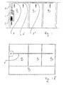
- Figure 1 shows a side cross-section through the spaces R1, R2, R3 with a prior art fire detecting apparatus mounted therein.
- a pipeline 5 connecting all the illustrated spaces R1, R2, R3, which has suction openings 3, 3 ', 3 "in the spaces R1, R2, R3 and which is connected in the space R1 to an arrangement which comprises a main detector 1 and a suction unit 7. If the suction unit 7 is in operation, room air is taken from the spaces R1, R2, R3 via the suction openings 3, 3 ', 3 "and fed to the main detector 1 via the pipe 5.
- FIG. 1A shows a plan view of the rooms of FIG. 1, wherein a room R4 (corridor) connecting the rooms R1, R2, R3 can be seen.
- the embodiment of a device for detecting fires according to the prior art shown here can easily recognize that a single detection of fire sources in the individual rooms R1, R2, R3 with such a device is not possible.
- the main detector 1 can perform no assignment of a fire characteristic to the region of origin in the intake air through the pipe 5.
- FIG. 2 shows a lateral cross section through the spaces R1, R2, R3 with a device for detecting fire sources mounted therein in accordance with the present invention.
- the suction openings 3, 3 ', 3 are equipped with sub-detectors 9, 9', 9", which are switched on by the main detector 1 in the event of the detection of a fire parameter.
- the switching on of the sub-detectors 9, 9 ', 9 " is in this embodiment of a controller 11 made via a corresponding radio signal.
- This controller 11 can be seen in a plan view in FIG. 2A, which shows a cross section through the spaces R1, R2, R3 of FIG.
- corresponding sub-alarm display devices 12, 12 ', 12 are also provided in the region of the doors of the room R4 (corridor) to the rooms R1, R2, R3.
- a fire parameter is detected by the main detector 1 and recorded in FIG the sequence via the controller 11, the activation of all sub-detectors 9, 9 ', 9 "triggered, can be detected on these sub-detectors 9, 9', 9" of the fire in one or more of the rooms R1, R2, R3.
- These sub-detectors 9, 9 ', 9 are in communication with the sub-alarm indicators 12, 12', 12" and signal the location of the fire in the room R4, so that incoming fire fighting forces can advance without further ado directly to the scene. Since the sub-detectors 9, 9 ', 9 "communicate with the controller 11 via radio, the transfer of the fire data via the controller 11 to an alarm display device in a central part of the building or in a fire panel is also possible.
- FIG. 3A shows a sectional side view of an open solenoid valve 20 arranged in an intake manifold, which consists of a closure body 21 which is pulled into its seat 22 with a magnetic coil 23.
- the control of the valve 20 is wired by the central transmission module via the line 24th
- Figure 3B shows a sectional side view of the solenoid valve of Fig. 3A, but now in the closed state.
- the design of the valve 20 is also possible with a spherical closure body 21, and / or with a housed in a spherical housing coil 23.
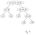
- FIG. 4 shows a schematic overview of the group-wise assignment of valves to explain the localization method according to the invention.
- the main detector detects an incipient fire, it starts an iterative localization process.
- 5 intake ports v1 to v5 are considered for monitoring 5 separate spaces.
- the two valves v1 and v2 are closed, but the other v3, v4, v5 remain open, e.g. the measured smoke level.
- the source of the fire is thus to be found in the group of closed valves v1 and v2.
- valves v3, v4, v5 and v1 are closed, leaving only v2 open. If the measured smoke level increases, the source of the fire is located at v2. Otherwise, v1 would be the source of the fire. It can be seen from the drawing that with 5 suction openings the fire can be localized after a maximum of 3 steps.
- the quantity of smoke-sucking intake openings is subdivided stepwise into 2 groups until this quantity contains only a single intake opening. With n steps, one can thus locate one from 2 n intake openings, as shown in the following table: Number of suction openings Number of steps to localize 1 ... 2 1 3 ... 4 2 5 ... 8 3 9 ... 16 4 ... ... (2 n-1 +1) ... 2 n n
Applications Claiming Priority (3)
| Application Number | Priority Date | Filing Date | Title |
|---|---|---|---|
| DE10125687 | 2001-05-25 | ||
| DE10125687A DE10125687B4 (de) | 2001-05-25 | 2001-05-25 | Vorrichtung zum Detektieren von Brandherden oder Gasverunreinigungen |
| PCT/EP2002/005734 WO2002095703A2 (de) | 2001-05-25 | 2002-05-24 | Vorrichtung und verfahren zum detektieren von brandherden oder gasverunreinigungen |
Publications (2)
| Publication Number | Publication Date |
|---|---|
| EP1397789A2 EP1397789A2 (de) | 2004-03-17 |
| EP1397789B1 true EP1397789B1 (de) | 2007-11-14 |
Family
ID=7686230
Family Applications (1)
| Application Number | Title | Priority Date | Filing Date |
|---|---|---|---|
| EP02747322A Expired - Lifetime EP1397789B1 (de) | 2001-05-25 | 2002-05-24 | Vorrichtung und verfahren zum detektieren von brandherden oder gasverunreinigungen |
Country Status (7)
| Country | Link |
|---|---|
| US (1) | US6985081B2 (zh) |
| EP (1) | EP1397789B1 (zh) |
| CN (1) | CN1331101C (zh) |
| AT (1) | ATE378660T1 (zh) |
| CA (1) | CA2447756C (zh) |
| DE (2) | DE10125687B4 (zh) |
| WO (1) | WO2002095703A2 (zh) |
Cited By (1)
| Publication number | Priority date | Publication date | Assignee | Title |
|---|---|---|---|---|
| EP3955226A1 (de) | 2020-08-12 | 2022-02-16 | Wagner Group GmbH | Ansaugpartikelerkennungssystem mit lichtleitsystem |
Families Citing this family (32)
| Publication number | Priority date | Publication date | Assignee | Title |
|---|---|---|---|---|
| DE10348565B4 (de) * | 2003-10-20 | 2007-01-04 | Wagner Alarm- Und Sicherungssysteme Gmbh | Verfahren und Vorrichtung zum Erkennen und Lokalisieren eines Brandes |
| DE10358531A1 (de) * | 2003-12-13 | 2005-07-28 | Minimax Gmbh & Co. Kg | Vorrichtung und Verfahren zum Detektieren von Entstehungsbränden |
| US7375642B2 (en) * | 2004-08-24 | 2008-05-20 | Wagner Alarm- Und Sicherungssysteme Gmbh | Method and device for identifying and localizing a fire |
| GB2430027A (en) * | 2005-09-09 | 2007-03-14 | Kidde Ip Holdings Ltd | Fibre bragg temperature sensors |
| EP1811478B1 (de) | 2006-01-07 | 2008-04-02 | Hekatron Vertriebs GmbH | Verfahren und Vorrichtung zur Erkennung eines Brandes |
| GB0805063D0 (en) * | 2008-03-18 | 2008-04-23 | No Climb Products Ltd | Testing of aspirating systems |
| EP2368236A1 (de) * | 2008-12-19 | 2011-09-28 | Minimax GmbH & Co. KG | Verfahren und vorrichtung zur früherkennung von bränden |
| JP5540085B2 (ja) * | 2009-06-05 | 2014-07-02 | エックストラリス・テクノロジーズ・リミテッド | ガス検出装置 |
| DE102009027034A1 (de) | 2009-06-18 | 2010-12-23 | Robert Bosch Gmbh | Einrichtung zur Früherkennung ungewöhnlicher Betriebszustände |
| EP2309468A1 (de) * | 2009-10-09 | 2011-04-13 | Amrona AG | Verfahren, Vorrichtung und Computerprogrammprodukt zur Projektierung eines Branderkennungssystems mit Absaugvorrichtung |
| EP2469492B1 (de) | 2010-11-29 | 2013-05-29 | Minimax GmbH & Co. KG | Verfahren und Vorrichtung zur Branddetektion in Volumina |
| CA2762561C (en) | 2010-12-23 | 2021-01-26 | Michael L. Hennegan | Fire sprinkler system having combined detection and distribution piping |
| US10426983B2 (en) | 2010-12-23 | 2019-10-01 | Michael L. Hennegan | Fire sprinkler system having combined detection and distribution piping |
| WO2013031016A1 (ja) * | 2011-09-02 | 2013-03-07 | 日本フェンオール株式会社 | 吸引式煙感知システム |
| EP2852870A4 (en) * | 2012-05-21 | 2016-04-27 | Xtralis Technologies Ltd | SAMPLING POINT FOR PARTICLE DETECTOR |
| CA2874395A1 (en) * | 2012-05-24 | 2013-12-19 | Douglas H. Lundy | Threat detection system having multi-hop, wifi or cellular network arrangement of wireless detectors, sensors and sub-sensors that report data and location non-compliance, and enable related devices while blanketing a venue |
| CN102979949A (zh) * | 2012-12-24 | 2013-03-20 | 苏州才子佳人文化传播有限公司 | 一种报警型气体泄露感应切断开关 |
| DE102013207605A1 (de) * | 2013-04-25 | 2014-10-30 | safetec Brandes und Niehoff GmbH | Rauchmeldeeinheit, Rauchmeldesystem sowie Rauchmeldervorrichtung |
| EP3069331B1 (en) * | 2013-11-14 | 2019-06-12 | Xtralis Global | Improvements to multi-point sampling valves |
| US9224281B2 (en) * | 2014-01-15 | 2015-12-29 | The Boeing Company | Smoke detector sensor network system and method |
| US9448126B2 (en) * | 2014-03-06 | 2016-09-20 | Infineon Technologies Ag | Single diaphragm transducer structure |
| EP2983145A1 (de) * | 2014-08-05 | 2016-02-10 | Siemens Schweiz AG | Meldersockel und Anschlussbasis zur lösbaren Anbringung eines Gefahrenmelders mit jeweils einer Funkeinrichtung zum Aussenden von Positionsdaten des Montageorts des Meldersockels bzw. der Anschlussbasis und/oder eines Verweises auf diese Positionsdaten |
| RU2622787C1 (ru) * | 2016-03-09 | 2017-06-20 | федеральное государственное бюджетное образовательное учреждение высшего образования "Южно-Российский государственный политехнический университет (НПИ) имени М.И. Платова" | Устройство для предотвращения и тушения пожаров и способ его возведения |
| US10885292B2 (en) * | 2016-09-21 | 2021-01-05 | International Business Machines Corporation | System, method and computer program product for pollution source attribution |
| ES2840775T3 (es) * | 2016-11-25 | 2021-07-07 | Wagner Group Gmbh | Dispositivo de filtrado |
| US10746714B2 (en) | 2017-06-16 | 2020-08-18 | International Business Machines Corporation | Air pollution source recognition based on dynamic pairing and comparison |
| EP3483585B1 (en) | 2017-11-13 | 2022-06-29 | Carrier Corporation | Air particulate detection system |
| WO2019222305A1 (en) * | 2018-05-15 | 2019-11-21 | Carrier Corporation | Electroactive actuators as sampling port valves for aspirating contaminant detection |
| EP3828853B1 (en) | 2019-11-29 | 2023-10-04 | Carrier Corporation | Aspiration smoke detector system |
| JP2021162598A (ja) * | 2020-03-31 | 2021-10-11 | ダイキン工業株式会社 | 検知ユニット、収容容器、検知装置 |
| CN112581735A (zh) * | 2020-12-14 | 2021-03-30 | 深圳市查知科技有限公司 | 一种吸气式感烟探测器故障定位系统及方法 |
| US11804118B2 (en) * | 2022-03-01 | 2023-10-31 | Honeywell International Inc. | Aspirating smoke detector discreet sample point |
Family Cites Families (14)
| Publication number | Priority date | Publication date | Assignee | Title |
|---|---|---|---|---|
| DE1154379B (de) * | 1962-05-12 | 1963-09-12 | Walther & Cie Ag | Akustischer Rauchmelder |
| NL187595C (nl) * | 1981-10-08 | 1991-11-18 | Westinghouse Electrotechniek E | Inrichting voor het detecteren van gas- of rookdeeltjes. |
| US4771808A (en) * | 1986-09-19 | 1988-09-20 | Alexander Controls Limited | Apparatus for controlling the flow of gas |
| US4764758A (en) * | 1987-07-01 | 1988-08-16 | Environment/One Corporation | Incipient fire detector II |
| US4818970A (en) * | 1987-08-13 | 1989-04-04 | Gpac, Inc. | Fire condition detection and control system for air moving and filtering units |
| FR2670010B1 (fr) * | 1990-12-03 | 1994-05-06 | Cerberus Guinard | Dispositif de detection de fumee par systeme aspirant. |
| JPH07506688A (ja) * | 1992-05-11 | 1995-07-20 | ビジョン システムズ インコーポレイティド | 煙検知走査装置に関する改良 |
| GB2274333B (en) * | 1993-01-07 | 1996-12-11 | Hochiki Co | Smoke detecting apparatus capable of detecting both smoke and fine particles |
| GB9315779D0 (en) * | 1993-07-30 | 1993-09-15 | Stoneplan Limited | Apparatus and methods |
| JP3648307B2 (ja) * | 1995-11-24 | 2005-05-18 | 日本フエンオール株式会社 | 煙検知システム |
| US6125710A (en) * | 1997-04-15 | 2000-10-03 | Phoenix Controls Corporation | Networked air measurement system |
| CA2291203A1 (en) * | 1998-12-04 | 2000-06-04 | George A. Schoenfelder | Aspirated detector with flow sensor |
| GB9910540D0 (en) * | 1999-05-08 | 1999-07-07 | Airsense Technology Ltd | Method and apparatus |
| US6685104B1 (en) * | 2002-07-17 | 2004-02-03 | Ardele Y. Float | Landscape sprinkling systems |
-
2001
- 2001-05-25 DE DE10125687A patent/DE10125687B4/de not_active Expired - Fee Related
-
2002
- 2002-05-24 US US10/478,375 patent/US6985081B2/en not_active Expired - Lifetime
- 2002-05-24 CA CA2447756A patent/CA2447756C/en not_active Expired - Fee Related
- 2002-05-24 EP EP02747322A patent/EP1397789B1/de not_active Expired - Lifetime
- 2002-05-24 AT AT02747322T patent/ATE378660T1/de active
- 2002-05-24 DE DE50211210T patent/DE50211210D1/de not_active Expired - Lifetime
- 2002-05-24 CN CNB028105958A patent/CN1331101C/zh not_active Expired - Fee Related
- 2002-05-24 WO PCT/EP2002/005734 patent/WO2002095703A2/de active IP Right Grant
Cited By (1)
| Publication number | Priority date | Publication date | Assignee | Title |
|---|---|---|---|---|
| EP3955226A1 (de) | 2020-08-12 | 2022-02-16 | Wagner Group GmbH | Ansaugpartikelerkennungssystem mit lichtleitsystem |
Also Published As
| Publication number | Publication date |
|---|---|
| CN1331101C (zh) | 2007-08-08 |
| CA2447756C (en) | 2014-12-09 |
| EP1397789A2 (de) | 2004-03-17 |
| WO2002095703A3 (de) | 2003-03-20 |
| US20040145484A1 (en) | 2004-07-29 |
| DE10125687B4 (de) | 2005-06-16 |
| WO2002095703A2 (de) | 2002-11-28 |
| CA2447756A1 (en) | 2002-11-28 |
| DE50211210D1 (de) | 2007-12-27 |
| ATE378660T1 (de) | 2007-11-15 |
| CN1514990A (zh) | 2004-07-21 |
| US6985081B2 (en) | 2006-01-10 |
| DE10125687A1 (de) | 2002-12-19 |
Similar Documents
| Publication | Publication Date | Title |
|---|---|---|
| EP1397789B1 (de) | Vorrichtung und verfahren zum detektieren von brandherden oder gasverunreinigungen | |
| EP1634261B1 (de) | Verfahren und vorrichtung zum erkennen und lokalisieren eines brandes | |
| EP1811478A1 (de) | Verfahren und Vorrichtung zur Erkennung eines Brandes | |
| DE2205634A1 (de) | Anlage zur Feuer und/oder Gasuberwa chung mehrerer Uberwachungsstellen | |
| CH691932A5 (de) | Armatur mit integrierbarer, permanenter Lecküberwachung. | |
| DE10164293A1 (de) | Verfahren und Vorrichtung zum Messen des Sauerstoffgehaltes | |
| EP1993082B1 (de) | Detektion und Ortsbestimmung eines Brandes | |
| WO2000022398A1 (de) | Folien-lecksucher | |
| EP1077371A1 (de) | Verfahren, Anordnung und Armatur zur Überwachung eines Rohrleitungssystems | |
| DE19605637C1 (de) | Verfahren zur Luftstromüberwachung in einer Branderkennungsvorrichtung sowie Branderkennungsvorrichtung zur Durchführung des Verfahrens | |
| EP1076211B1 (de) | Vorrichtung zur Rauchfreihaltung von Rettungswegen in Gebäuden | |
| EP0640210A1 (en) | Improvements relating to smoke detection scanning apparatus | |
| EP0774742B1 (de) | Branddetektor | |
| DE102017111017A1 (de) | Leuchtenbaldachin zum Detektieren und Signalisieren unterschiedlicher Gefahrensituationen | |
| EP1030279B1 (de) | Verfahren zum Detektieren von Entstehungsbränden und aspirative Branderkennungsvorrichtung zur Durchführung des Verfahrens | |
| DE2704570C3 (de) | Brandmeldeanlage, insbesondere für einen Autotunnel | |
| DE102004057000B3 (de) | Sensorgesteuertes Notfall- und Evakuierungssystem für Großobjekte | |
| DE102018106253B3 (de) | Leuchtenbaldachin zum Detektieren und Signalisieren von Gefahrensituationen | |
| DE3935238C2 (de) | Luftführungssystem, insbesondere für ein Brandmeldegerät | |
| EP3091375B1 (de) | Blitzwarnvorrichtung | |
| EP1360669A1 (de) | Verfahren und einrichtung zur überwachung unterirdischer anlagen | |
| EP0911774B1 (de) | Raumüberwachungssensor | |
| DE102016202845A1 (de) | Vorrichtung und Verfahren zum Erfassen eines Belegungszustands eines Parkflächenabschnitts eines Parkplatzes und Parkplatz | |
| DE2364202C2 (de) | Brandmeldeanlage für einen Autotunnel | |
| DE102020123176A1 (de) | Verfahren zur Überwachung der Luftqualität in einem Gebäude und Raumluftüberwachungseinrichtung |
Legal Events
| Date | Code | Title | Description |
|---|---|---|---|
| PUAI | Public reference made under article 153(3) epc to a published international application that has entered the european phase |
Free format text: ORIGINAL CODE: 0009012 |
|
| 17P | Request for examination filed |
Effective date: 20031106 |
|
| AK | Designated contracting states |
Kind code of ref document: A2 Designated state(s): AT BE CH CY DE DK ES FI FR GB GR IE IT LI LU MC NL PT SE TR |
|
| AX | Request for extension of the european patent |
Extension state: AL LT LV MK RO SI |
|
| GRAP | Despatch of communication of intention to grant a patent |
Free format text: ORIGINAL CODE: EPIDOSNIGR1 |
|
| GRAS | Grant fee paid |
Free format text: ORIGINAL CODE: EPIDOSNIGR3 |
|
| GRAA | (expected) grant |
Free format text: ORIGINAL CODE: 0009210 |
|
| AK | Designated contracting states |
Kind code of ref document: B1 Designated state(s): AT BE CH CY DE DK ES FI FR GB GR IE IT LI LU MC NL PT SE TR |
|
| REG | Reference to a national code |
Ref country code: GB Ref legal event code: FG4D Free format text: NOT ENGLISH |
|
| REG | Reference to a national code |
Ref country code: CH Ref legal event code: EP |
|
| GBT | Gb: translation of ep patent filed (gb section 77(6)(a)/1977) |
Effective date: 20071114 |
|
| REG | Reference to a national code |
Ref country code: IE Ref legal event code: FG4D Free format text: LANGUAGE OF EP DOCUMENT: GERMAN |
|
| REF | Corresponds to: |
Ref document number: 50211210 Country of ref document: DE Date of ref document: 20071227 Kind code of ref document: P |
|
| REG | Reference to a national code |
Ref country code: CH Ref legal event code: NV Representative=s name: FELBER & PARTNER AG PATENTANWAELTE |
|
| PG25 | Lapsed in a contracting state [announced via postgrant information from national office to epo] |
Ref country code: NL Free format text: LAPSE BECAUSE OF FAILURE TO SUBMIT A TRANSLATION OF THE DESCRIPTION OR TO PAY THE FEE WITHIN THE PRESCRIBED TIME-LIMIT Effective date: 20071114 Ref country code: SE Free format text: LAPSE BECAUSE OF FAILURE TO SUBMIT A TRANSLATION OF THE DESCRIPTION OR TO PAY THE FEE WITHIN THE PRESCRIBED TIME-LIMIT Effective date: 20080214 Ref country code: ES Free format text: LAPSE BECAUSE OF FAILURE TO SUBMIT A TRANSLATION OF THE DESCRIPTION OR TO PAY THE FEE WITHIN THE PRESCRIBED TIME-LIMIT Effective date: 20080225 |
|
| NLV1 | Nl: lapsed or annulled due to failure to fulfill the requirements of art. 29p and 29m of the patents act | ||
| PG25 | Lapsed in a contracting state [announced via postgrant information from national office to epo] |
Ref country code: FI Free format text: LAPSE BECAUSE OF FAILURE TO SUBMIT A TRANSLATION OF THE DESCRIPTION OR TO PAY THE FEE WITHIN THE PRESCRIBED TIME-LIMIT Effective date: 20071114 |
|
| PG25 | Lapsed in a contracting state [announced via postgrant information from national office to epo] |
Ref country code: DK Free format text: LAPSE BECAUSE OF FAILURE TO SUBMIT A TRANSLATION OF THE DESCRIPTION OR TO PAY THE FEE WITHIN THE PRESCRIBED TIME-LIMIT Effective date: 20071114 |
|
| ET | Fr: translation filed | ||
| PLBE | No opposition filed within time limit |
Free format text: ORIGINAL CODE: 0009261 |
|
| STAA | Information on the status of an ep patent application or granted ep patent |
Free format text: STATUS: NO OPPOSITION FILED WITHIN TIME LIMIT |
|
| PG25 | Lapsed in a contracting state [announced via postgrant information from national office to epo] |
Ref country code: PT Free format text: LAPSE BECAUSE OF FAILURE TO SUBMIT A TRANSLATION OF THE DESCRIPTION OR TO PAY THE FEE WITHIN THE PRESCRIBED TIME-LIMIT Effective date: 20080414 |
|
| REG | Reference to a national code |
Ref country code: IE Ref legal event code: FD4D |
|
| 26N | No opposition filed |
Effective date: 20080815 |
|
| PG25 | Lapsed in a contracting state [announced via postgrant information from national office to epo] |
Ref country code: IE Free format text: LAPSE BECAUSE OF FAILURE TO SUBMIT A TRANSLATION OF THE DESCRIPTION OR TO PAY THE FEE WITHIN THE PRESCRIBED TIME-LIMIT Effective date: 20071114 |
|
| BERE | Be: lapsed |
Owner name: WAGNER ALARM- UND SICHERUNGSSYSTEME G.M.B.H. Effective date: 20080531 |
|
| PG25 | Lapsed in a contracting state [announced via postgrant information from national office to epo] |
Ref country code: MC Free format text: LAPSE BECAUSE OF NON-PAYMENT OF DUE FEES Effective date: 20080531 |
|
| PG25 | Lapsed in a contracting state [announced via postgrant information from national office to epo] |
Ref country code: GR Free format text: LAPSE BECAUSE OF FAILURE TO SUBMIT A TRANSLATION OF THE DESCRIPTION OR TO PAY THE FEE WITHIN THE PRESCRIBED TIME-LIMIT Effective date: 20080215 |
|
| PG25 | Lapsed in a contracting state [announced via postgrant information from national office to epo] |
Ref country code: BE Free format text: LAPSE BECAUSE OF NON-PAYMENT OF DUE FEES Effective date: 20080531 |
|
| PG25 | Lapsed in a contracting state [announced via postgrant information from national office to epo] |
Ref country code: CY Free format text: LAPSE BECAUSE OF FAILURE TO SUBMIT A TRANSLATION OF THE DESCRIPTION OR TO PAY THE FEE WITHIN THE PRESCRIBED TIME-LIMIT Effective date: 20071114 |
|
| PG25 | Lapsed in a contracting state [announced via postgrant information from national office to epo] |
Ref country code: LU Free format text: LAPSE BECAUSE OF NON-PAYMENT OF DUE FEES Effective date: 20080524 |
|
| PG25 | Lapsed in a contracting state [announced via postgrant information from national office to epo] |
Ref country code: TR Free format text: LAPSE BECAUSE OF FAILURE TO SUBMIT A TRANSLATION OF THE DESCRIPTION OR TO PAY THE FEE WITHIN THE PRESCRIBED TIME-LIMIT Effective date: 20071114 |
|
| PG25 | Lapsed in a contracting state [announced via postgrant information from national office to epo] |
Ref country code: IT Free format text: LAPSE BECAUSE OF NON-PAYMENT OF DUE FEES Effective date: 20080531 |
|
| REG | Reference to a national code |
Ref country code: GB Ref legal event code: 732E Free format text: REGISTERED BETWEEN 20111201 AND 20111207 |
|
| REG | Reference to a national code |
Ref country code: CH Ref legal event code: PFUS Owner name: WAGNER GROUP GMBH, DE Free format text: FORMER OWNER: WAGNER ALARM- UND SICHERUNGSSYSTEME GMBH, DE |
|
| REG | Reference to a national code |
Ref country code: FR Ref legal event code: CD Owner name: WAGNER GROUP GMBH, DE Effective date: 20120216 Ref country code: FR Ref legal event code: TP Owner name: WAGNER GROUP GMBH, DE Effective date: 20120216 |
|
| REG | Reference to a national code |
Ref country code: AT Ref legal event code: PC Ref document number: 378660 Country of ref document: AT Kind code of ref document: T Owner name: WAGNER GROUP GMBH, DE Effective date: 20120418 |
|
| REG | Reference to a national code |
Ref country code: FR Ref legal event code: PLFP Year of fee payment: 15 |
|
| PGFP | Annual fee paid to national office [announced via postgrant information from national office to epo] |
Ref country code: GB Payment date: 20160520 Year of fee payment: 15 Ref country code: CH Payment date: 20160519 Year of fee payment: 15 Ref country code: DE Payment date: 20160520 Year of fee payment: 15 |
|
| PGFP | Annual fee paid to national office [announced via postgrant information from national office to epo] |
Ref country code: AT Payment date: 20160520 Year of fee payment: 15 Ref country code: FR Payment date: 20160520 Year of fee payment: 15 |
|
| REG | Reference to a national code |
Ref country code: CH Ref legal event code: PCAR Free format text: NEW ADDRESS: DUFOURSTRASSE 116, 8008 ZUERICH (CH) |
|
| REG | Reference to a national code |
Ref country code: DE Ref legal event code: R119 Ref document number: 50211210 Country of ref document: DE |
|
| REG | Reference to a national code |
Ref country code: CH Ref legal event code: PL |
|
| REG | Reference to a national code |
Ref country code: AT Ref legal event code: MM01 Ref document number: 378660 Country of ref document: AT Kind code of ref document: T Effective date: 20170524 |
|
| GBPC | Gb: european patent ceased through non-payment of renewal fee |
Effective date: 20170524 |
|
| PG25 | Lapsed in a contracting state [announced via postgrant information from national office to epo] |
Ref country code: AT Free format text: LAPSE BECAUSE OF NON-PAYMENT OF DUE FEES Effective date: 20170524 |
|
| PG25 | Lapsed in a contracting state [announced via postgrant information from national office to epo] |
Ref country code: CH Free format text: LAPSE BECAUSE OF NON-PAYMENT OF DUE FEES Effective date: 20170531 Ref country code: LI Free format text: LAPSE BECAUSE OF NON-PAYMENT OF DUE FEES Effective date: 20170531 |
|
| REG | Reference to a national code |
Ref country code: FR Ref legal event code: ST Effective date: 20180131 |
|
| PG25 | Lapsed in a contracting state [announced via postgrant information from national office to epo] |
Ref country code: DE Free format text: LAPSE BECAUSE OF NON-PAYMENT OF DUE FEES Effective date: 20171201 Ref country code: GB Free format text: LAPSE BECAUSE OF NON-PAYMENT OF DUE FEES Effective date: 20170524 |
|
| PG25 | Lapsed in a contracting state [announced via postgrant information from national office to epo] |
Ref country code: FR Free format text: LAPSE BECAUSE OF NON-PAYMENT OF DUE FEES Effective date: 20170531 |