EP1396466A1 - Flurförderzeug mit einer seitlichen Batterieentnahmeöffnung - Google Patents
Flurförderzeug mit einer seitlichen Batterieentnahmeöffnung Download PDFInfo
- Publication number
- EP1396466A1 EP1396466A1 EP03019251A EP03019251A EP1396466A1 EP 1396466 A1 EP1396466 A1 EP 1396466A1 EP 03019251 A EP03019251 A EP 03019251A EP 03019251 A EP03019251 A EP 03019251A EP 1396466 A1 EP1396466 A1 EP 1396466A1
- Authority
- EP
- European Patent Office
- Prior art keywords
- roller conveyor
- industrial truck
- battery
- battery compartment
- movable part
- Prior art date
- Legal status (The legal status is an assumption and is not a legal conclusion. Google has not performed a legal analysis and makes no representation as to the accuracy of the status listed.)
- Granted
Links
- 238000005096 rolling process Methods 0.000 claims description 2
Images

Classifications
-
- B—PERFORMING OPERATIONS; TRANSPORTING
- B66—HOISTING; LIFTING; HAULING
- B66F—HOISTING, LIFTING, HAULING OR PUSHING, NOT OTHERWISE PROVIDED FOR, e.g. DEVICES WHICH APPLY A LIFTING OR PUSHING FORCE DIRECTLY TO THE SURFACE OF A LOAD
- B66F9/00—Devices for lifting or lowering bulky or heavy goods for loading or unloading purposes
- B66F9/06—Devices for lifting or lowering bulky or heavy goods for loading or unloading purposes movable, with their loads, on wheels or the like, e.g. fork-lift trucks
- B66F9/075—Constructional features or details
- B66F9/07513—Details concerning the chassis
- B66F9/0754—Battery removal arrangements
-
- B—PERFORMING OPERATIONS; TRANSPORTING
- B60—VEHICLES IN GENERAL
- B60L—PROPULSION OF ELECTRICALLY-PROPELLED VEHICLES; SUPPLYING ELECTRIC POWER FOR AUXILIARY EQUIPMENT OF ELECTRICALLY-PROPELLED VEHICLES; ELECTRODYNAMIC BRAKE SYSTEMS FOR VEHICLES IN GENERAL; MAGNETIC SUSPENSION OR LEVITATION FOR VEHICLES; MONITORING OPERATING VARIABLES OF ELECTRICALLY-PROPELLED VEHICLES; ELECTRIC SAFETY DEVICES FOR ELECTRICALLY-PROPELLED VEHICLES
- B60L50/00—Electric propulsion with power supplied within the vehicle
- B60L50/50—Electric propulsion with power supplied within the vehicle using propulsion power supplied by batteries or fuel cells
- B60L50/60—Electric propulsion with power supplied within the vehicle using propulsion power supplied by batteries or fuel cells using power supplied by batteries
- B60L50/66—Arrangements of batteries
-
- B—PERFORMING OPERATIONS; TRANSPORTING
- B60—VEHICLES IN GENERAL
- B60L—PROPULSION OF ELECTRICALLY-PROPELLED VEHICLES; SUPPLYING ELECTRIC POWER FOR AUXILIARY EQUIPMENT OF ELECTRICALLY-PROPELLED VEHICLES; ELECTRODYNAMIC BRAKE SYSTEMS FOR VEHICLES IN GENERAL; MAGNETIC SUSPENSION OR LEVITATION FOR VEHICLES; MONITORING OPERATING VARIABLES OF ELECTRICALLY-PROPELLED VEHICLES; ELECTRIC SAFETY DEVICES FOR ELECTRICALLY-PROPELLED VEHICLES
- B60L53/00—Methods of charging batteries, specially adapted for electric vehicles; Charging stations or on-board charging equipment therefor; Exchange of energy storage elements in electric vehicles
- B60L53/80—Exchanging energy storage elements, e.g. removable batteries
-
- B—PERFORMING OPERATIONS; TRANSPORTING
- B60—VEHICLES IN GENERAL
- B60K—ARRANGEMENT OR MOUNTING OF PROPULSION UNITS OR OF TRANSMISSIONS IN VEHICLES; ARRANGEMENT OR MOUNTING OF PLURAL DIVERSE PRIME-MOVERS IN VEHICLES; AUXILIARY DRIVES FOR VEHICLES; INSTRUMENTATION OR DASHBOARDS FOR VEHICLES; ARRANGEMENTS IN CONNECTION WITH COOLING, AIR INTAKE, GAS EXHAUST OR FUEL SUPPLY OF PROPULSION UNITS IN VEHICLES
- B60K1/00—Arrangement or mounting of electrical propulsion units
- B60K1/04—Arrangement or mounting of electrical propulsion units of the electric storage means for propulsion
-
- B—PERFORMING OPERATIONS; TRANSPORTING
- B60—VEHICLES IN GENERAL
- B60L—PROPULSION OF ELECTRICALLY-PROPELLED VEHICLES; SUPPLYING ELECTRIC POWER FOR AUXILIARY EQUIPMENT OF ELECTRICALLY-PROPELLED VEHICLES; ELECTRODYNAMIC BRAKE SYSTEMS FOR VEHICLES IN GENERAL; MAGNETIC SUSPENSION OR LEVITATION FOR VEHICLES; MONITORING OPERATING VARIABLES OF ELECTRICALLY-PROPELLED VEHICLES; ELECTRIC SAFETY DEVICES FOR ELECTRICALLY-PROPELLED VEHICLES
- B60L2200/00—Type of vehicles
- B60L2200/40—Working vehicles
- B60L2200/44—Industrial trucks or floor conveyors
-
- Y—GENERAL TAGGING OF NEW TECHNOLOGICAL DEVELOPMENTS; GENERAL TAGGING OF CROSS-SECTIONAL TECHNOLOGIES SPANNING OVER SEVERAL SECTIONS OF THE IPC; TECHNICAL SUBJECTS COVERED BY FORMER USPC CROSS-REFERENCE ART COLLECTIONS [XRACs] AND DIGESTS
- Y02—TECHNOLOGIES OR APPLICATIONS FOR MITIGATION OR ADAPTATION AGAINST CLIMATE CHANGE
- Y02P—CLIMATE CHANGE MITIGATION TECHNOLOGIES IN THE PRODUCTION OR PROCESSING OF GOODS
- Y02P90/00—Enabling technologies with a potential contribution to greenhouse gas [GHG] emissions mitigation
- Y02P90/60—Electric or hybrid propulsion means for production processes
-
- Y—GENERAL TAGGING OF NEW TECHNOLOGICAL DEVELOPMENTS; GENERAL TAGGING OF CROSS-SECTIONAL TECHNOLOGIES SPANNING OVER SEVERAL SECTIONS OF THE IPC; TECHNICAL SUBJECTS COVERED BY FORMER USPC CROSS-REFERENCE ART COLLECTIONS [XRACs] AND DIGESTS
- Y02—TECHNOLOGIES OR APPLICATIONS FOR MITIGATION OR ADAPTATION AGAINST CLIMATE CHANGE
- Y02T—CLIMATE CHANGE MITIGATION TECHNOLOGIES RELATED TO TRANSPORTATION
- Y02T10/00—Road transport of goods or passengers
- Y02T10/60—Other road transportation technologies with climate change mitigation effect
- Y02T10/70—Energy storage systems for electromobility, e.g. batteries
-
- Y—GENERAL TAGGING OF NEW TECHNOLOGICAL DEVELOPMENTS; GENERAL TAGGING OF CROSS-SECTIONAL TECHNOLOGIES SPANNING OVER SEVERAL SECTIONS OF THE IPC; TECHNICAL SUBJECTS COVERED BY FORMER USPC CROSS-REFERENCE ART COLLECTIONS [XRACs] AND DIGESTS
- Y02—TECHNOLOGIES OR APPLICATIONS FOR MITIGATION OR ADAPTATION AGAINST CLIMATE CHANGE
- Y02T—CLIMATE CHANGE MITIGATION TECHNOLOGIES RELATED TO TRANSPORTATION
- Y02T10/00—Road transport of goods or passengers
- Y02T10/60—Other road transportation technologies with climate change mitigation effect
- Y02T10/7072—Electromobility specific charging systems or methods for batteries, ultracapacitors, supercapacitors or double-layer capacitors
-
- Y—GENERAL TAGGING OF NEW TECHNOLOGICAL DEVELOPMENTS; GENERAL TAGGING OF CROSS-SECTIONAL TECHNOLOGIES SPANNING OVER SEVERAL SECTIONS OF THE IPC; TECHNICAL SUBJECTS COVERED BY FORMER USPC CROSS-REFERENCE ART COLLECTIONS [XRACs] AND DIGESTS
- Y02—TECHNOLOGIES OR APPLICATIONS FOR MITIGATION OR ADAPTATION AGAINST CLIMATE CHANGE
- Y02T—CLIMATE CHANGE MITIGATION TECHNOLOGIES RELATED TO TRANSPORTATION
- Y02T90/00—Enabling technologies or technologies with a potential or indirect contribution to GHG emissions mitigation
- Y02T90/10—Technologies relating to charging of electric vehicles
- Y02T90/12—Electric charging stations
-
- Y—GENERAL TAGGING OF NEW TECHNOLOGICAL DEVELOPMENTS; GENERAL TAGGING OF CROSS-SECTIONAL TECHNOLOGIES SPANNING OVER SEVERAL SECTIONS OF THE IPC; TECHNICAL SUBJECTS COVERED BY FORMER USPC CROSS-REFERENCE ART COLLECTIONS [XRACs] AND DIGESTS
- Y02—TECHNOLOGIES OR APPLICATIONS FOR MITIGATION OR ADAPTATION AGAINST CLIMATE CHANGE
- Y02T—CLIMATE CHANGE MITIGATION TECHNOLOGIES RELATED TO TRANSPORTATION
- Y02T90/00—Enabling technologies or technologies with a potential or indirect contribution to GHG emissions mitigation
- Y02T90/10—Technologies relating to charging of electric vehicles
- Y02T90/14—Plug-in electric vehicles
Definitions
- the invention relates to an industrial truck, in particular a forklift, with a Battery compartment and a battery block that is horizontal by a side Opening of the battery compartment is movable relative to the battery compartment, one Bottom surface of the battery compartment is equipped with a roller conveyor.
- the invention is therefore based on the object of an industrial truck of the beginning to provide the type mentioned, in which a battery change without external Roller conveyor is possible.
- the roller conveyor of Truck is made in two or more parts, with at least part of the Roller conveyor can be moved out of the battery compartment in such a way that the battery block is completely movable out of the truck on the roller conveyor.
- the battery block located completely outside the truck can then be directly can be lifted for example by means of a crane.
- An additional external Roller conveyor is not required.
- a part of the truck's roller conveyor always remains on the bottom of the battery compartment.
- the other parts of the Roller conveyor inside the industrial truck can be used to change the Battery blocks are arranged in extension of the first part to the To be able to move the battery block completely out of the truck.
- the Inserting a new battery block then takes place in reverse order, the Battery block is e.g. by means of a crane on the extended roller conveyor removed and then pushed into the battery compartment. Subsequently the movable parts of the roller conveyor are also moved into the battery compartment.
- the roller conveyor therefore preferably has a part which is fixed to the vehicle and which is in the region of the Bottom of the battery compartment is arranged.
- the roller conveyor has at least one movable part, which is in a retracted position in the area of the bottom of the battery compartment and the can be extended into an extended position in the extension of the vehicle-fixed part.
- the movable part of the Roller conveyor provided a movable support with which the roller conveyor on a Roadway is supported. With the support, the weight of one on the Roller conveyor located outside of the truck directly on the battery block Lane are supported. This is necessary because of the large weight of the Battery blocks could otherwise cause the truck to tip over.
- the movable part of the roller conveyor has a stop, which is the end position of the battery packs located outside the truck on the roller conveyor Are defined.
- the stop ensures that the battery pack is not over the end of the Roller conveyor rolls out and falls off the roller conveyor.
- the But stop the position of the battery pack in which the battery pack is completely is located outside the truck and can therefore be lifted safely.
- the stop is movable on the movable part of the roller conveyor is arranged such that the is in the Battery block located on the roller conveyor outside the truck protrudes outwards beyond the end of the roller conveyor.
- the attack so movably arranged on the movable part of the roller conveyor that the Stop with retracted position of the movable part completely within the Contour of the truck is movable.
- the movable stop enables one Execution of the roller conveyor, consisting of a fixed part and only one movable part, which is guided on the fixed part.
- the holding device expediently stands in such a manner with the roller conveyor Active connection that only causes the battery pack to roll out of the battery compartment fully extended and movable part of the Roller conveyor is possible. This also prevents operating errors on the roller conveyor, For example, forgetting to drop the support or a incomplete extension of the roller conveyor.
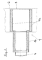
- Figure 1 shows an extended roller conveyor 1 arranged in an industrial truck a vehicle-fixed part 1a and a movable part 1b in plan view.
- the Part 1a fixed to the vehicle is completely within the contour 2 of the industrial truck arranged.
- the outlines of one on the roller conveyor 1 can also be seen standing battery pack 3, which is located in the battery compartment of the truck.
- the movable part 1b of the roller conveyor is in its extended position.
- the battery block 3 can on the roller conveyor 1 to the left in the drawing up to a stop 4 arranged on the movable part 1b.
- the Stop 4 also serves as a handle for moving the movable part 1b. During the operation of the industrial truck, the movable part 1b and Stop moved to the right in the drawing, so that it too is completely are within the contour of the truck.
- FIG. 2 shows the roller conveyor 1 according to FIG. 1 in a side view.
- the Battery block 3 is on the right in its position completely in the truck and shown on the left in its position completely outside the truck.
Landscapes
- Engineering & Computer Science (AREA)
- Transportation (AREA)
- Mechanical Engineering (AREA)
- Life Sciences & Earth Sciences (AREA)
- Power Engineering (AREA)
- Structural Engineering (AREA)
- Sustainable Development (AREA)
- Sustainable Energy (AREA)
- Civil Engineering (AREA)
- Geology (AREA)
- Forklifts And Lifting Vehicles (AREA)
- Arrangement Or Mounting Of Propulsion Units For Vehicles (AREA)
Abstract
Description
- Figur 1
- eine ausgefahrene Rollenbahn in Draufsicht,
- Figur 2
- eine ausgefahrene Rollenbahn in Seitenansicht.
Claims (10)
- Flurförderzeug, insbesondere Gabelstapler, mit einem Batteriefach und ein, Batterieblock (3), der in horizontaler Richtung durch eine seitliche Öffnung des Batteriefachs relativ zu dem Batteriefach bewegbar ist, wobei eine Bodenfläche des Batteriefachs mit einer Rollenbahn (1) ausgerüstet ist, dadurch gekennzeichnet, dass die Rollenbahn (1) zwei- oder mehrteilig ausgeführt ist, wobei mindestens ein Teil (1b) der Rollenbahn (1) derart aus dem Batteriefach heraus bewegbar ist, dass der Batterieblock (3) auf der Rollenbahn (1) vollständig aus dem Flurförderzeug heraus bewegbar ist.
- Flurförderzeug nach Anspruch 1, dadurch gekennzeichnet, dass die Rollenbahn (1) einen fahrzeugfesten Teil (1a) aufweist, der im Bereich des Bodens des Batteriefachs angeordnet ist.
- Flurförderzeug nach Anspruch 1 oder 2, dadurch gekennzeichnet, dass die Rollenbahn (1) mindestens einen bewegbaren Teil (1b) aufweist, der sich in einer zurückgezogenen Stellung im Bereich des Bodens des Batteriefachs befindet und der in Verlängerung des fahrzeugfesten Teils (1a) in eine ausgefahrene Stellung ausfahrbar ist.
- Flurförderzeug nach einem der Ansprüche 1 bis 3, dadurch gekennzeichnet, dass an dem bewegbaren Teil (1b) der Rollenbahn (1 ) eine bewegbare Stütze (5) vorgesehen ist, mit der die Rollenbahn (1) an einer Fahrbahn abstützbar ist.
- Flurförderzeug nach einem der Ansprüche 1 bis 4, dadurch gekennzeichnet, dass der bewegbare Teil (1b) der Rollenbahn (1) einen Anschlag (4) aufweist, der die Endlage des sich außerhalb des Flurförderzeugs auf der Rollenbahn (1) befindlichen Batterieblocks definiert.
- Flurförderzeug nach Anspruch 5, dadurch gekennzeichnet, dass der Anschlag (4) bewegbar an dem bewegbaren Teil (1b) der Rollenbahn (1) angeordnet ist, derart, dass der sich in der Endlage außerhalb des Flurförderzeugs auf der Rollenbahn (1) befindliche Batterieblock (3) nach außen über das Ende der Rollenbahn (1) hinaus ragt.
- Flurförderzeug nach Anspruch 5 oder 6, dadurch gekennzeichnet, dass der Anschlag (4) bewegbar an dem bewegbaren Teil (1b) der Rollenbahn (1) angeordnet ist, derart, dass der Anschlag (4) bei zurückgezogener Stellung des bewegbaren Teils (1b) vollständig innerhalb die Kontur des Flurförderzeugs bewegbar ist.
- Flurförderzeug nach einem der Ansprüche 5 bis 7, dadurch gekennzeichnet, dass der Anschlag (4) als Griff zum Bewegen des bewegbaren Teils (1b) der Rollenbahn (1) ausgeführt ist.
- Flurförderzeug nach einem der Ansprüche 1 bis 8, dadurch gekennzeichnet, dass das Flurförderzeug eine Haltevorrichtung aufweist, mit der ein unbeabsichtigtes Herausrollen des Batterieblocks aus dem Batteriefach verhindert ist.
- Flurförderzeug nach Anspruch 9, dadurch gekennzeichnet, dass die Haltevorrichtung derart mit der Rollenbahn (1) in Wirkverbindung steht, das ein Herausrollen des Batterieblocks aus dem Batteriefach nur bei vollständig ausgefahrenem und an der Fahrbahn abgestütztem bewegbaren Teil (1b) der Rollenbahn (1) möglich ist.
Applications Claiming Priority (2)
| Application Number | Priority Date | Filing Date | Title |
|---|---|---|---|
| DE10241418 | 2002-09-06 | ||
| DE10241418A DE10241418A1 (de) | 2002-09-06 | 2002-09-06 | Flurförderzeug mit einer seitlichen Batterieentnahmeöffnung |
Publications (2)
| Publication Number | Publication Date |
|---|---|
| EP1396466A1 true EP1396466A1 (de) | 2004-03-10 |
| EP1396466B1 EP1396466B1 (de) | 2007-10-03 |
Family
ID=31502460
Family Applications (1)
| Application Number | Title | Priority Date | Filing Date |
|---|---|---|---|
| EP03019251A Expired - Lifetime EP1396466B1 (de) | 2002-09-06 | 2003-08-26 | Flurförderzeug mit einer seitlichen Batterieentnahmeöffnung |
Country Status (4)
| Country | Link |
|---|---|
| US (1) | US20050008465A1 (de) |
| EP (1) | EP1396466B1 (de) |
| JP (1) | JP4546706B2 (de) |
| DE (2) | DE10241418A1 (de) |
Cited By (2)
| Publication number | Priority date | Publication date | Assignee | Title |
|---|---|---|---|---|
| EP2266827A1 (de) | 2009-06-26 | 2010-12-29 | Trepel Airport Equipment GmbH | Elektromotorisch antreibbares Flughafenbodenfahrzeug |
| EP2287041A1 (de) * | 2009-08-21 | 2011-02-23 | Fahrzeugwerk Bernard Krone GmbH | Fahrzeugaufbau |
Families Citing this family (18)
| Publication number | Priority date | Publication date | Assignee | Title |
|---|---|---|---|---|
| DE10248657A1 (de) * | 2002-10-18 | 2004-04-29 | Still Gmbh | Gabelstapler mit einem seitlich entnehmbaren Batterieblock |
| GB2411389B (en) * | 2003-11-10 | 2006-07-05 | Lansing Linde Ltd | Battery replacement system for an industrial truck |
| DE102004000023A1 (de) * | 2004-08-17 | 2006-02-23 | Kuraray Specialities Europe Gmbh | Verfahren zur Herstellung von Folienlaminaten für Verbundverglasungen aus Teilfolien unterschiedlicher Zusammensetzung |
| DE102004056624A1 (de) | 2004-11-24 | 2006-06-01 | Still Gmbh | Flurförderzeug mit einer bewegbaren Aufstandsfläche für einen Batterieblock |
| DE102005051058A1 (de) * | 2005-10-25 | 2007-04-26 | Still Gmbh | Flurförderzeug mit einer bewegbaren Aufstandsfläche für einen Batterieblock |
| DE102006017889A1 (de) * | 2006-04-13 | 2007-10-25 | Linde Material Handling Gmbh | Flurförderzeug mit einer Batterie und Verfahren zum Betrieb eines Flurförderzeugs mit einer Batterie |
| DE102007006890A1 (de) | 2007-02-13 | 2008-08-14 | Linde Material Handling Gmbh | Flurförderzeug mit Stützhebel für den Batterieblock |
| DE102007043544A1 (de) | 2007-03-14 | 2008-09-18 | Linde Material Handling Gmbh | Flurförderzeug mit Batterieblock und geteiltem Wechselschlitten |
| DE102007025332B4 (de) * | 2007-05-31 | 2025-05-28 | Jungheinrich Aktiengesellschaft | Flurförderzeug, insbesondere Gabelstapler |
| DE102008004651B4 (de) | 2008-01-16 | 2023-05-11 | Still Gesellschaft Mit Beschränkter Haftung | Flurförderzeug, insbesondere Gegengewichtsgabelstapler |
| DE102009020081A1 (de) | 2009-05-06 | 2010-11-11 | Still Gmbh | Flurförderzeug, insbesondere Gegengewichtsgabelstapler |
| WO2012170286A1 (en) | 2011-06-07 | 2012-12-13 | Crown Equipment Corporation | Battery transfer apparatus |
| CN102673536B (zh) * | 2012-05-31 | 2014-10-15 | 亿源动力(北京)科技有限公司 | 电池装填单元、电池换电设备以及电池装填方法 |
| MX368015B (es) | 2015-10-15 | 2019-09-13 | Grupo Bimbo Sab De Cv | Sistema de abastecimiento e intercambio de banco de baterías en un vehículo eléctrico de uso comercial. |
| TWI703583B (zh) * | 2015-11-30 | 2020-09-01 | 美商Tn美國有限責任公司 | 用於傳送、旋轉及/或檢查之罐體移動總成及罐體移動方法 |
| KR20250041618A (ko) | 2017-07-13 | 2025-03-25 | 에티움, 엘엘씨 | 지게차 용 모듈식 리튬-이온 배터리 시스템 |
| US12266953B1 (en) | 2020-08-17 | 2025-04-01 | Econtrols, Llc | Dual chemistry rechargeable battery system for use in electric APU-equipped commercial trucks |
| CA3218420A1 (en) | 2021-06-04 | 2022-12-08 | Kennon Guglielmo | Lithium-ion battery charging system for fork lifts |
Citations (5)
| Publication number | Priority date | Publication date | Assignee | Title |
|---|---|---|---|---|
| US3327875A (en) * | 1964-06-30 | 1967-06-27 | Lansing Bagnall Ltd | Lift truck having battery removal apparatus |
| GB2091179A (en) * | 1981-01-20 | 1982-07-28 | Jungheinrich Kg | Lift truck |
| DE3839618A1 (de) * | 1988-11-24 | 1990-05-31 | Linde Ag | Fahrzeug mit einem batterie-elektrischen antrieb |
| JPH08165094A (ja) * | 1994-12-09 | 1996-06-25 | Nippon Yusoki Co Ltd | 産業車両のバッテリーテーブル |
| JP2002274789A (ja) * | 2001-03-19 | 2002-09-25 | Nippon Yusoki Co Ltd | バッテリ式フォークリフト |
Family Cites Families (18)
| Publication number | Priority date | Publication date | Assignee | Title |
|---|---|---|---|---|
| US2627960A (en) * | 1947-07-18 | 1953-02-10 | Journal Company | Loading conveyer |
| US3068983A (en) * | 1959-05-27 | 1962-12-18 | Wilkie Company | Cantilever telescopic conveyor |
| US3122244A (en) * | 1962-05-24 | 1964-02-25 | Samuel S Corso | Battery remover and replacer apparatus |
| US3374878A (en) * | 1966-07-25 | 1968-03-26 | Andrew T. Kornylak | Roller conveyor system |
| US3497090A (en) * | 1968-04-03 | 1970-02-24 | Allis Chalmers Mfg Co | Combined battery case and counterweight |
| US4333788A (en) * | 1980-04-04 | 1982-06-08 | Cooper Tire & Rubber Company | Tire building machine servicer |
| US4459732A (en) * | 1981-09-21 | 1984-07-17 | Driggers Robert H | Stove roller |
| JPS58170397U (ja) * | 1982-05-07 | 1983-11-14 | 株式会社豊田自動織機製作所 | リ−チ式フオ−クリフトにおけるバツテリ−ケ−スの引き出し装置 |
| US4991674A (en) * | 1989-08-09 | 1991-02-12 | Crown Equipment Corporation | Forklift truck battery retainer with spring |
| JPH0549441U (ja) * | 1991-12-17 | 1993-06-29 | 小松フォークリフト株式会社 | フォークリフトトラックのバッテリー出し入れ装置 |
| US5387064A (en) * | 1993-12-16 | 1995-02-07 | Cardinal Materials Flow, Inc. | Movable shelf structure for truck |
| US5544998A (en) * | 1994-03-31 | 1996-08-13 | Mascotech Automotive Systems Group, Inc. | Selectively retractable vehicle load floor |
| US5934725A (en) * | 1997-06-09 | 1999-08-10 | Bowers; Jerald A. | Extendable vehicle bed sliding tray |
| US5806948A (en) * | 1997-06-16 | 1998-09-15 | Rowan, Sr.; W. Frank | Retrofittable battery cabinet for telecommunications enclosures |
| US6045172A (en) * | 1998-05-21 | 2000-04-04 | Thomas; John Joseph | Pick-up truck bed extending device |
| US6397999B1 (en) * | 1999-01-04 | 2002-06-04 | Laurence Edward Taylor | Baggage receiving device |
| US6244646B1 (en) * | 1999-12-06 | 2001-06-12 | Wheeler Bros., Inc. | Storage and retrieval assembly for a vehicle cargo area |
| DE10006617C1 (de) * | 2000-02-15 | 2001-07-12 | Daimler Chrysler Ag | Ausfahrbarer Ladeboden für ein Kraftfahrzeug |
-
2002
- 2002-09-06 DE DE10241418A patent/DE10241418A1/de not_active Withdrawn
-
2003
- 2003-08-26 EP EP03019251A patent/EP1396466B1/de not_active Expired - Lifetime
- 2003-08-26 DE DE50308311T patent/DE50308311D1/de not_active Expired - Lifetime
- 2003-08-28 US US10/651,292 patent/US20050008465A1/en not_active Abandoned
- 2003-09-04 JP JP2003312846A patent/JP4546706B2/ja not_active Expired - Fee Related
Patent Citations (5)
| Publication number | Priority date | Publication date | Assignee | Title |
|---|---|---|---|---|
| US3327875A (en) * | 1964-06-30 | 1967-06-27 | Lansing Bagnall Ltd | Lift truck having battery removal apparatus |
| GB2091179A (en) * | 1981-01-20 | 1982-07-28 | Jungheinrich Kg | Lift truck |
| DE3839618A1 (de) * | 1988-11-24 | 1990-05-31 | Linde Ag | Fahrzeug mit einem batterie-elektrischen antrieb |
| JPH08165094A (ja) * | 1994-12-09 | 1996-06-25 | Nippon Yusoki Co Ltd | 産業車両のバッテリーテーブル |
| JP2002274789A (ja) * | 2001-03-19 | 2002-09-25 | Nippon Yusoki Co Ltd | バッテリ式フォークリフト |
Non-Patent Citations (2)
| Title |
|---|
| PATENT ABSTRACTS OF JAPAN vol. 1996, no. 10 31 October 1996 (1996-10-31) * |
| PATENT ABSTRACTS OF JAPAN vol. 2003, no. 01 14 January 2003 (2003-01-14) * |
Cited By (2)
| Publication number | Priority date | Publication date | Assignee | Title |
|---|---|---|---|---|
| EP2266827A1 (de) | 2009-06-26 | 2010-12-29 | Trepel Airport Equipment GmbH | Elektromotorisch antreibbares Flughafenbodenfahrzeug |
| EP2287041A1 (de) * | 2009-08-21 | 2011-02-23 | Fahrzeugwerk Bernard Krone GmbH | Fahrzeugaufbau |
Also Published As
| Publication number | Publication date |
|---|---|
| JP2004099324A (ja) | 2004-04-02 |
| DE10241418A1 (de) | 2004-03-18 |
| JP4546706B2 (ja) | 2010-09-15 |
| EP1396466B1 (de) | 2007-10-03 |
| DE50308311D1 (de) | 2007-11-15 |
| US20050008465A1 (en) | 2005-01-13 |
Similar Documents
| Publication | Publication Date | Title |
|---|---|---|
| EP1396466B1 (de) | Flurförderzeug mit einer seitlichen Batterieentnahmeöffnung | |
| EP1935731B1 (de) | Gabelstapler mit einer Führung zur seitlichen Batterieentnahme | |
| EP0011250B1 (de) | Fahrzeug zum Laden und Transportieren von Schwergut, insbesondere von Kraftfahrzeugen | |
| EP1415874B1 (de) | Batteriewechselsystem für ein Flurförderzeug | |
| DE19846000A1 (de) | Flurförderzeug mit einem Batterieblock | |
| DE102004052067A1 (de) | Batteriewechselsystem für ein Flurförderzeug | |
| EP1925588B1 (de) | Gabelstapler mit einer Führung zum seitlichen Ausziehen eines Batterieblocks | |
| EP2953887B1 (de) | Vorrichtung zur aufnahme und zum transport von lasten | |
| DE60115484T2 (de) | System zum zweiseitigem laden von lastkraftwagen | |
| EP1661847B1 (de) | Flurförderzeug mit einer bewegbaren Aufstandsfläche für einen Batterieblock | |
| DE202019003416U1 (de) | Fahrerloses, mit elektrisch aufladbarer Batterie ausgerüstetes, motorisch angetriebenes Fahrzeug | |
| EP2518007B1 (de) | Flurförderzeug, insbesondere Gegengewichtsgabelstapler | |
| DE19512246C2 (de) | Selbstfahrendes und auf ein Transportfahrzeug selbstauf- und selbstabladbares Verladesystem für Container oder Wechselbrücken | |
| DE102005022094A1 (de) | Flurförderzeug mit einem seitlich ausziehbaren Batterieblock | |
| EP3147255B1 (de) | Wechselvorrichtung für traktionsbatterie eines flurförderzeugs | |
| DE102013110811A1 (de) | Flurförderzeug mit einem ein- und ausfahrbaren Wechselschlitten einer Energieversorgungseinheit | |
| DE3920632A1 (de) | Aufbau, insbesondere kastenaufbau, fuer ein transportfahrzeug (lkw) | |
| DE10361322A1 (de) | Zur Wartung von Fahrzeugen verwendete Hebebühne | |
| DE3839618A1 (de) | Fahrzeug mit einem batterie-elektrischen antrieb | |
| DE2648251C2 (de) | Lastkraftfahrzeug mit einer Hebeeinrichtung | |
| DE102015116346A1 (de) | Wechselvorrichtung für Traktionsbatterie eines Flurförderzeugs | |
| DE19700272B4 (de) | Flurförderzeug, insbesondere deichselgeführtes Flurförderzeug | |
| AT522493A2 (de) | Fahrbare Hubeinrichtung in Leichtbau | |
| DE19634216C2 (de) | Lastaufnahmemittel zur doppeltiefen Ein- beziehungsweise Auslagerung von palletierten Ladeeinheiten | |
| EP2518005B1 (de) | Flurförderzeug |
Legal Events
| Date | Code | Title | Description |
|---|---|---|---|
| PUAI | Public reference made under article 153(3) epc to a published international application that has entered the european phase |
Free format text: ORIGINAL CODE: 0009012 |
|
| AK | Designated contracting states |
Kind code of ref document: A1 Designated state(s): AT BE BG CH CY CZ DE DK EE ES FI FR GB GR HU IE IT LI LU MC NL PT RO SE SI SK TR |
|
| AX | Request for extension of the european patent |
Extension state: AL LT LV MK |
|
| RIN1 | Information on inventor provided before grant (corrected) |
Inventor name: BUCHMANN, MICHAEL Inventor name: GERDES, TORSTEN Inventor name: SZYMANSKI, MAREK Inventor name: BALLHAUSEN, STEPHAN |
|
| 17P | Request for examination filed |
Effective date: 20040812 |
|
| AKX | Designation fees paid |
Designated state(s): DE FR GB IT |
|
| 17Q | First examination report despatched |
Effective date: 20060928 |
|
| GRAP | Despatch of communication of intention to grant a patent |
Free format text: ORIGINAL CODE: EPIDOSNIGR1 |
|
| GRAS | Grant fee paid |
Free format text: ORIGINAL CODE: EPIDOSNIGR3 |
|
| GRAA | (expected) grant |
Free format text: ORIGINAL CODE: 0009210 |
|
| AK | Designated contracting states |
Kind code of ref document: B1 Designated state(s): DE FR GB IT |
|
| REG | Reference to a national code |
Ref country code: GB Ref legal event code: FG4D Free format text: NOT ENGLISH |
|
| REF | Corresponds to: |
Ref document number: 50308311 Country of ref document: DE Date of ref document: 20071115 Kind code of ref document: P |
|
| GBT | Gb: translation of ep patent filed (gb section 77(6)(a)/1977) |
Effective date: 20071212 |
|
| ET | Fr: translation filed | ||
| PLBE | No opposition filed within time limit |
Free format text: ORIGINAL CODE: 0009261 |
|
| STAA | Information on the status of an ep patent application or granted ep patent |
Free format text: STATUS: NO OPPOSITION FILED WITHIN TIME LIMIT |
|
| 26N | No opposition filed |
Effective date: 20080704 |
|
| PGFP | Annual fee paid to national office [announced via postgrant information from national office to epo] |
Ref country code: GB Payment date: 20110824 Year of fee payment: 9 |
|
| PGFP | Annual fee paid to national office [announced via postgrant information from national office to epo] |
Ref country code: IT Payment date: 20120824 Year of fee payment: 10 |
|
| GBPC | Gb: european patent ceased through non-payment of renewal fee |
Effective date: 20120826 |
|
| PG25 | Lapsed in a contracting state [announced via postgrant information from national office to epo] |
Ref country code: GB Free format text: LAPSE BECAUSE OF NON-PAYMENT OF DUE FEES Effective date: 20120826 |
|
| PG25 | Lapsed in a contracting state [announced via postgrant information from national office to epo] |
Ref country code: IT Free format text: LAPSE BECAUSE OF NON-PAYMENT OF DUE FEES Effective date: 20130826 |
|
| PGFP | Annual fee paid to national office [announced via postgrant information from national office to epo] |
Ref country code: FR Payment date: 20140819 Year of fee payment: 12 |
|
| PGFP | Annual fee paid to national office [announced via postgrant information from national office to epo] |
Ref country code: DE Payment date: 20150820 Year of fee payment: 13 |
|
| REG | Reference to a national code |
Ref country code: FR Ref legal event code: ST Effective date: 20160429 |
|
| PG25 | Lapsed in a contracting state [announced via postgrant information from national office to epo] |
Ref country code: FR Free format text: LAPSE BECAUSE OF NON-PAYMENT OF DUE FEES Effective date: 20150831 |
|
| REG | Reference to a national code |
Ref country code: DE Ref legal event code: R119 Ref document number: 50308311 Country of ref document: DE |
|
| PG25 | Lapsed in a contracting state [announced via postgrant information from national office to epo] |
Ref country code: DE Free format text: LAPSE BECAUSE OF NON-PAYMENT OF DUE FEES Effective date: 20170301 |