EP1396326A1 - Bauteil zum Verbinden einer Fluidleitung mit einer Öffnung eines Kunststoffbehälters - Google Patents
Bauteil zum Verbinden einer Fluidleitung mit einer Öffnung eines Kunststoffbehälters Download PDFInfo
- Publication number
- EP1396326A1 EP1396326A1 EP20030011989 EP03011989A EP1396326A1 EP 1396326 A1 EP1396326 A1 EP 1396326A1 EP 20030011989 EP20030011989 EP 20030011989 EP 03011989 A EP03011989 A EP 03011989A EP 1396326 A1 EP1396326 A1 EP 1396326A1
- Authority
- EP
- European Patent Office
- Prior art keywords
- component
- container
- tubular
- welded
- component according
- Prior art date
- Legal status (The legal status is an assumption and is not a legal conclusion. Google has not performed a legal analysis and makes no representation as to the accuracy of the status listed.)
- Granted
Links
Images


Classifications
-
- B—PERFORMING OPERATIONS; TRANSPORTING
- B60—VEHICLES IN GENERAL
- B60K—ARRANGEMENT OR MOUNTING OF PROPULSION UNITS OR OF TRANSMISSIONS IN VEHICLES; ARRANGEMENT OR MOUNTING OF PLURAL DIVERSE PRIME-MOVERS IN VEHICLES; AUXILIARY DRIVES FOR VEHICLES; INSTRUMENTATION OR DASHBOARDS FOR VEHICLES; ARRANGEMENTS IN CONNECTION WITH COOLING, AIR INTAKE, GAS EXHAUST OR FUEL SUPPLY OF PROPULSION UNITS IN VEHICLES
- B60K15/00—Arrangement in connection with fuel supply of combustion engines or other fuel consuming energy converters, e.g. fuel cells; Mounting or construction of fuel tanks
- B60K15/03—Fuel tanks
- B60K15/035—Fuel tanks characterised by venting means
- B60K15/03519—Valve arrangements in the vent line
-
- B—PERFORMING OPERATIONS; TRANSPORTING
- B29—WORKING OF PLASTICS; WORKING OF SUBSTANCES IN A PLASTIC STATE IN GENERAL
- B29C—SHAPING OR JOINING OF PLASTICS; SHAPING OF MATERIAL IN A PLASTIC STATE, NOT OTHERWISE PROVIDED FOR; AFTER-TREATMENT OF THE SHAPED PRODUCTS, e.g. REPAIRING
- B29C45/00—Injection moulding, i.e. forcing the required volume of moulding material through a nozzle into a closed mould; Apparatus therefor
- B29C45/16—Making multilayered or multicoloured articles
- B29C45/1642—Making multilayered or multicoloured articles having a "sandwich" structure
- B29C45/1643—Making multilayered or multicoloured articles having a "sandwich" structure from at least three different materials or with at least four layers
-
- B—PERFORMING OPERATIONS; TRANSPORTING
- B29—WORKING OF PLASTICS; WORKING OF SUBSTANCES IN A PLASTIC STATE IN GENERAL
- B29C—SHAPING OR JOINING OF PLASTICS; SHAPING OF MATERIAL IN A PLASTIC STATE, NOT OTHERWISE PROVIDED FOR; AFTER-TREATMENT OF THE SHAPED PRODUCTS, e.g. REPAIRING
- B29C65/00—Joining or sealing of preformed parts, e.g. welding of plastics materials; Apparatus therefor
- B29C65/02—Joining or sealing of preformed parts, e.g. welding of plastics materials; Apparatus therefor by heating, with or without pressure
-
- B—PERFORMING OPERATIONS; TRANSPORTING
- B29—WORKING OF PLASTICS; WORKING OF SUBSTANCES IN A PLASTIC STATE IN GENERAL
- B29C—SHAPING OR JOINING OF PLASTICS; SHAPING OF MATERIAL IN A PLASTIC STATE, NOT OTHERWISE PROVIDED FOR; AFTER-TREATMENT OF THE SHAPED PRODUCTS, e.g. REPAIRING
- B29C66/00—General aspects of processes or apparatus for joining preformed parts
- B29C66/01—General aspects dealing with the joint area or with the area to be joined
- B29C66/05—Particular design of joint configurations
- B29C66/10—Particular design of joint configurations particular design of the joint cross-sections
- B29C66/11—Joint cross-sections comprising a single joint-segment, i.e. one of the parts to be joined comprising a single joint-segment in the joint cross-section
- B29C66/112—Single lapped joints
- B29C66/1122—Single lap to lap joints, i.e. overlap joints
-
- B—PERFORMING OPERATIONS; TRANSPORTING
- B29—WORKING OF PLASTICS; WORKING OF SUBSTANCES IN A PLASTIC STATE IN GENERAL
- B29C—SHAPING OR JOINING OF PLASTICS; SHAPING OF MATERIAL IN A PLASTIC STATE, NOT OTHERWISE PROVIDED FOR; AFTER-TREATMENT OF THE SHAPED PRODUCTS, e.g. REPAIRING
- B29C66/00—General aspects of processes or apparatus for joining preformed parts
- B29C66/01—General aspects dealing with the joint area or with the area to be joined
- B29C66/05—Particular design of joint configurations
- B29C66/10—Particular design of joint configurations particular design of the joint cross-sections
- B29C66/13—Single flanged joints; Fin-type joints; Single hem joints; Edge joints; Interpenetrating fingered joints; Other specific particular designs of joint cross-sections not provided for in groups B29C66/11 - B29C66/12
- B29C66/131—Single flanged joints, i.e. one of the parts to be joined being rigid and flanged in the joint area
-
- B—PERFORMING OPERATIONS; TRANSPORTING
- B29—WORKING OF PLASTICS; WORKING OF SUBSTANCES IN A PLASTIC STATE IN GENERAL
- B29C—SHAPING OR JOINING OF PLASTICS; SHAPING OF MATERIAL IN A PLASTIC STATE, NOT OTHERWISE PROVIDED FOR; AFTER-TREATMENT OF THE SHAPED PRODUCTS, e.g. REPAIRING
- B29C66/00—General aspects of processes or apparatus for joining preformed parts
- B29C66/50—General aspects of joining tubular articles; General aspects of joining long products, i.e. bars or profiled elements; General aspects of joining single elements to tubular articles, hollow articles or bars; General aspects of joining several hollow-preforms to form hollow or tubular articles
- B29C66/51—Joining tubular articles, profiled elements or bars; Joining single elements to tubular articles, hollow articles or bars; Joining several hollow-preforms to form hollow or tubular articles
- B29C66/53—Joining single elements to tubular articles, hollow articles or bars
- B29C66/532—Joining single elements to the wall of tubular articles, hollow articles or bars
- B29C66/5324—Joining single elements to the wall of tubular articles, hollow articles or bars said single elements being substantially annular, i.e. of finite length
- B29C66/53245—Joining single elements to the wall of tubular articles, hollow articles or bars said single elements being substantially annular, i.e. of finite length said articles being hollow
- B29C66/53246—Joining single elements to the wall of tubular articles, hollow articles or bars said single elements being substantially annular, i.e. of finite length said articles being hollow said single elements being spouts, e.g. joining spouts to containers
- B29C66/53247—Joining single elements to the wall of tubular articles, hollow articles or bars said single elements being substantially annular, i.e. of finite length said articles being hollow said single elements being spouts, e.g. joining spouts to containers said spouts comprising flanges
-
- B—PERFORMING OPERATIONS; TRANSPORTING
- B29—WORKING OF PLASTICS; WORKING OF SUBSTANCES IN A PLASTIC STATE IN GENERAL
- B29C—SHAPING OR JOINING OF PLASTICS; SHAPING OF MATERIAL IN A PLASTIC STATE, NOT OTHERWISE PROVIDED FOR; AFTER-TREATMENT OF THE SHAPED PRODUCTS, e.g. REPAIRING
- B29C66/00—General aspects of processes or apparatus for joining preformed parts
- B29C66/70—General aspects of processes or apparatus for joining preformed parts characterised by the composition, physical properties or the structure of the material of the parts to be joined; Joining with non-plastics material
- B29C66/72—General aspects of processes or apparatus for joining preformed parts characterised by the composition, physical properties or the structure of the material of the parts to be joined; Joining with non-plastics material characterised by the structure of the material of the parts to be joined
- B29C66/723—General aspects of processes or apparatus for joining preformed parts characterised by the composition, physical properties or the structure of the material of the parts to be joined; Joining with non-plastics material characterised by the structure of the material of the parts to be joined being multi-layered
- B29C66/7234—General aspects of processes or apparatus for joining preformed parts characterised by the composition, physical properties or the structure of the material of the parts to be joined; Joining with non-plastics material characterised by the structure of the material of the parts to be joined being multi-layered comprising a barrier layer
-
- F—MECHANICAL ENGINEERING; LIGHTING; HEATING; WEAPONS; BLASTING
- F16—ENGINEERING ELEMENTS AND UNITS; GENERAL MEASURES FOR PRODUCING AND MAINTAINING EFFECTIVE FUNCTIONING OF MACHINES OR INSTALLATIONS; THERMAL INSULATION IN GENERAL
- F16L—PIPES; JOINTS OR FITTINGS FOR PIPES; SUPPORTS FOR PIPES, CABLES OR PROTECTIVE TUBING; MEANS FOR THERMAL INSULATION IN GENERAL
- F16L47/00—Connecting arrangements or other fittings specially adapted to be made of plastics or to be used with pipes made of plastics
- F16L47/26—Connecting arrangements or other fittings specially adapted to be made of plastics or to be used with pipes made of plastics for branching pipes; for joining pipes to walls; Adaptors therefor
- F16L47/28—Joining pipes to walls or to other pipes, the axis of the joined pipe being perpendicular to the wall or to the axis of the other pipe
-
- B—PERFORMING OPERATIONS; TRANSPORTING
- B29—WORKING OF PLASTICS; WORKING OF SUBSTANCES IN A PLASTIC STATE IN GENERAL
- B29C—SHAPING OR JOINING OF PLASTICS; SHAPING OF MATERIAL IN A PLASTIC STATE, NOT OTHERWISE PROVIDED FOR; AFTER-TREATMENT OF THE SHAPED PRODUCTS, e.g. REPAIRING
- B29C45/00—Injection moulding, i.e. forcing the required volume of moulding material through a nozzle into a closed mould; Apparatus therefor
- B29C45/16—Making multilayered or multicoloured articles
- B29C45/1642—Making multilayered or multicoloured articles having a "sandwich" structure
- B29C45/1646—Injecting parison-like articles
- B29C2045/1648—Injecting parison-like articles the parison core layer being a barrier material
-
- B—PERFORMING OPERATIONS; TRANSPORTING
- B29—WORKING OF PLASTICS; WORKING OF SUBSTANCES IN A PLASTIC STATE IN GENERAL
- B29C—SHAPING OR JOINING OF PLASTICS; SHAPING OF MATERIAL IN A PLASTIC STATE, NOT OTHERWISE PROVIDED FOR; AFTER-TREATMENT OF THE SHAPED PRODUCTS, e.g. REPAIRING
- B29C45/00—Injection moulding, i.e. forcing the required volume of moulding material through a nozzle into a closed mould; Apparatus therefor
- B29C45/16—Making multilayered or multicoloured articles
- B29C45/1642—Making multilayered or multicoloured articles having a "sandwich" structure
- B29C2045/1654—Making multilayered or multicoloured articles having a "sandwich" structure whereby the core material is penetrating through the skin
-
- B—PERFORMING OPERATIONS; TRANSPORTING
- B29—WORKING OF PLASTICS; WORKING OF SUBSTANCES IN A PLASTIC STATE IN GENERAL
- B29C—SHAPING OR JOINING OF PLASTICS; SHAPING OF MATERIAL IN A PLASTIC STATE, NOT OTHERWISE PROVIDED FOR; AFTER-TREATMENT OF THE SHAPED PRODUCTS, e.g. REPAIRING
- B29C65/00—Joining or sealing of preformed parts, e.g. welding of plastics materials; Apparatus therefor
- B29C65/02—Joining or sealing of preformed parts, e.g. welding of plastics materials; Apparatus therefor by heating, with or without pressure
- B29C65/06—Joining or sealing of preformed parts, e.g. welding of plastics materials; Apparatus therefor by heating, with or without pressure using friction, e.g. spin welding
-
- B—PERFORMING OPERATIONS; TRANSPORTING
- B29—WORKING OF PLASTICS; WORKING OF SUBSTANCES IN A PLASTIC STATE IN GENERAL
- B29C—SHAPING OR JOINING OF PLASTICS; SHAPING OF MATERIAL IN A PLASTIC STATE, NOT OTHERWISE PROVIDED FOR; AFTER-TREATMENT OF THE SHAPED PRODUCTS, e.g. REPAIRING
- B29C66/00—General aspects of processes or apparatus for joining preformed parts
- B29C66/70—General aspects of processes or apparatus for joining preformed parts characterised by the composition, physical properties or the structure of the material of the parts to be joined; Joining with non-plastics material
- B29C66/71—General aspects of processes or apparatus for joining preformed parts characterised by the composition, physical properties or the structure of the material of the parts to be joined; Joining with non-plastics material characterised by the composition of the plastics material of the parts to be joined
-
- B—PERFORMING OPERATIONS; TRANSPORTING
- B29—WORKING OF PLASTICS; WORKING OF SUBSTANCES IN A PLASTIC STATE IN GENERAL
- B29K—INDEXING SCHEME ASSOCIATED WITH SUBCLASSES B29B, B29C OR B29D, RELATING TO MOULDING MATERIALS OR TO MATERIALS FOR MOULDS, REINFORCEMENTS, FILLERS OR PREFORMED PARTS, e.g. INSERTS
- B29K2995/00—Properties of moulding materials, reinforcements, fillers, preformed parts or moulds
- B29K2995/0003—Properties of moulding materials, reinforcements, fillers, preformed parts or moulds having particular electrical or magnetic properties, e.g. piezoelectric
- B29K2995/0005—Conductive
-
- B—PERFORMING OPERATIONS; TRANSPORTING
- B29—WORKING OF PLASTICS; WORKING OF SUBSTANCES IN A PLASTIC STATE IN GENERAL
- B29K—INDEXING SCHEME ASSOCIATED WITH SUBCLASSES B29B, B29C OR B29D, RELATING TO MOULDING MATERIALS OR TO MATERIALS FOR MOULDS, REINFORCEMENTS, FILLERS OR PREFORMED PARTS, e.g. INSERTS
- B29K2995/00—Properties of moulding materials, reinforcements, fillers, preformed parts or moulds
- B29K2995/0037—Other properties
- B29K2995/0065—Permeability to gases
- B29K2995/0067—Permeability to gases non-permeable
-
- B—PERFORMING OPERATIONS; TRANSPORTING
- B29—WORKING OF PLASTICS; WORKING OF SUBSTANCES IN A PLASTIC STATE IN GENERAL
- B29L—INDEXING SCHEME ASSOCIATED WITH SUBCLASS B29C, RELATING TO PARTICULAR ARTICLES
- B29L2031/00—Other particular articles
- B29L2031/712—Containers; Packaging elements or accessories, Packages
- B29L2031/7172—Fuel tanks, jerry cans
-
- B—PERFORMING OPERATIONS; TRANSPORTING
- B60—VEHICLES IN GENERAL
- B60K—ARRANGEMENT OR MOUNTING OF PROPULSION UNITS OR OF TRANSMISSIONS IN VEHICLES; ARRANGEMENT OR MOUNTING OF PLURAL DIVERSE PRIME-MOVERS IN VEHICLES; AUXILIARY DRIVES FOR VEHICLES; INSTRUMENTATION OR DASHBOARDS FOR VEHICLES; ARRANGEMENTS IN CONNECTION WITH COOLING, AIR INTAKE, GAS EXHAUST OR FUEL SUPPLY OF PROPULSION UNITS IN VEHICLES
- B60K15/00—Arrangement in connection with fuel supply of combustion engines or other fuel consuming energy converters, e.g. fuel cells; Mounting or construction of fuel tanks
- B60K15/03—Fuel tanks
- B60K15/04—Tank inlets
-
- Y—GENERAL TAGGING OF NEW TECHNOLOGICAL DEVELOPMENTS; GENERAL TAGGING OF CROSS-SECTIONAL TECHNOLOGIES SPANNING OVER SEVERAL SECTIONS OF THE IPC; TECHNICAL SUBJECTS COVERED BY FORMER USPC CROSS-REFERENCE ART COLLECTIONS [XRACs] AND DIGESTS
- Y10—TECHNICAL SUBJECTS COVERED BY FORMER USPC
- Y10S—TECHNICAL SUBJECTS COVERED BY FORMER USPC CROSS-REFERENCE ART COLLECTIONS [XRACs] AND DIGESTS
- Y10S285/00—Pipe joints or couplings
- Y10S285/919—Resinous
-
- Y—GENERAL TAGGING OF NEW TECHNOLOGICAL DEVELOPMENTS; GENERAL TAGGING OF CROSS-SECTIONAL TECHNOLOGIES SPANNING OVER SEVERAL SECTIONS OF THE IPC; TECHNICAL SUBJECTS COVERED BY FORMER USPC CROSS-REFERENCE ART COLLECTIONS [XRACs] AND DIGESTS
- Y10—TECHNICAL SUBJECTS COVERED BY FORMER USPC
- Y10T—TECHNICAL SUBJECTS COVERED BY FORMER US CLASSIFICATION
- Y10T137/00—Fluid handling
- Y10T137/2931—Diverse fluid containing pressure systems
- Y10T137/3003—Fluid separating traps or vents
- Y10T137/3084—Discriminating outlet for gas
- Y10T137/309—Fluid sensing valve
- Y10T137/3099—Float responsive
Definitions
- the invention relates to a component for connecting a fluid line with an opening of a predominantly made of thermoplastic material, in particular polyolefin, existing container or for closing the opening, wherein the component at least a first and a second component of predominantly thermoplastic Plastic, the material of the first Component with the material of the container a fusion bond received by welding, but not sufficient Diffusion barrier to hydrocarbons, like gasoline or diesel, and the material the second component a significantly higher Diffusion barrier capability and lower swelling capacity towards hydrocarbons and a higher mechanical Strength, even after a hydrocarbon attack, and a higher dimensional stability in the Has heat as the material of the first component.
- a pipe-like nozzle contains the first Component polyethylene (PE), especially high density Polyethylene (HDPE), and the second component polyamide (PA).
- PE polyethylene
- HDPE high density Polyethylene
- PA polyamide
- One of the container to which the pipe socket to be welded, remote section the first component is of the material of second component overmoulded. A ring part of the first Component is welded to the container.
- the container also contains essentially HDPE. He goes when welding a fusion with the first component.
- the polyamide of the second component has a high diffusion barrier capability and low Swellability to fuels, such as gasoline or diesel oil, and in addition a high mechanical Strength.
- the invention is based on the object, a component specify the type mentioned, in which an outlet fuel is prevented to a greater extent.
- a first solution to this problem is inventively in that the material of the first component is the second component at least up to an injection point includes one to be welded to the container Area of the component in as large as possible as far away as possible and over the Material of the second component in the still plastic Soil of the material of the first component injected has been.
- a second solution to this problem is inventively in that the material of the second component is the first component at least up to an injection point includes one to be welded to the container Area of the component in the largest possible to largest possible Removal is gone and about the material of the first component through the still plastic soul of the Material of the second component through to the on Container to be welded surface has been injected is.
- the blocking ability is in the overlap area the two components against diffusing of fuels continues to be high, because the diffusing through by the almost diffusion-tight second component is largely prevented. Furthermore is the mechanical strength and heat-dimensional stability very high in the overlap area. Furthermore allows the injection of the material of the one component into the still plastic soul of the other component the manufacture of the component in the same mold.
- the component largely is tubular and in the first solution the material the second component and the second solution the material of the first component most of the Length of the pipe wall fills. Accordingly, that is Component also virtually diffusion-proof over almost its entire length and stable as the material of the second component.
- Both the first and the second solution can the ring member between itself and a coaxial tubular Extension of the component to limit a coaxial annular groove, and the axial thickness of the ring member and the Depth of the annular groove can be chosen so that the thickness after welding that surface to the container because of partially laterally evasive melt of the ring member significantly lower than before welding, but the bottom of the ring groove remains at a distance from the Containers.
- the ring part on Container thus reduces the thickness of the ring member through the laterally evasive melt of the ring part, allowing the fuel to diffuse therethrough after welding still remaining ring surface in the ring groove is very small, but still the material the second component remains trapped.
- Both the first and the second solution can the material of the first component is a polyolefin, in particular a functionalized PE, having with the material of the container is melted.
- the second component at least one of the materials EVOH, PA, POM, PEN, PBT, PET, PBN, LCP, PPS, PPA, PP, aliphatic polyketone and fluorothermoplastics.
- the materials EVOH, PA and PP go at least with the functionalized PE of a component during injection of the Material of the other component in the first component a fusion that not only cohesive, but also form-fitting.
- the other materials is the same for practically all polyolefins and / or copolymers after corresponding modification.
- the first component and the second solution the first component includes a third component, through the at least one of the properties Strength, diffusion barrier and heat dimensional stability of the component is increased.
- This third Component can also be characterized in the second or first component are arranged that their material into the still plastic soul of the second or first Component is injected. This too can be in the same Forming done in which the first and second Component to be shaped.
- the third component can be predominantly one of the materials EVOH, PA, POM, PEN, PBT, PET, PBN, LCP, PPS, PPA, aliphatic polyketone and fluorothermoplastic, so that the properties of strength, diffusion barrier ability and heat dimensional stability of the component be improved.
- At least the first component can, in per se known Way (DE 38 28 696 A1), an electrically conductive Have additional, so that the component through a moving along a surface of the component along Fuel, in particular when passing from Fuel through a tubular component, not electrostatically charged and igniting the Fuel by a spark discharge in the component is avoided.
- the component can be substantially U- or trapezoidal in cross-section be so that it as a closure (lid or Plug) can serve for the container opening.
- At least one of such a molded component another functional part be injection molded, e.g. a bracket clip, the e.g. for holding a fluid line or an electrical cable can serve.
- the component shown in Fig. 1 represents a tubular Neck, which consists of two components 1 and 2 exists and on the edge of an opening 4 of a container. 5 is welded, of which only part of its wall is shown.
- the container 5 serves to receive the Fuel, especially gasoline or diesel, one Motor vehicle and the pipe socket for connecting a not shown fluid line with the opening 4 of the Container over which the container filled with fuel becomes.
- the container 5 is usually multi-layered, wherein its outer layer of HDPE and a middle layer is made of a material that does not diffuse fuel through leaves.
- the materials of the first component 1 and the second Component 2 contain predominantly thermoplastic Plastic.
- the material of the first component 1 is so chosen, it with the material of the container 5 a Melt bond by friction welding or mirror welding received. If necessary, it has no adequate Diffusion barrier to hydrocarbons, like gasoline or diesel. Besides, it has one relatively low mechanical strength, which is why it sometimes has a gain. Furthermore, it has a relative high swelling capacity towards hydrocarbons, like gasoline or diesel.
- This is the first component 1 is a polyolefin, in particular a functionalized PE (polyethylene), which is compatible with the material of Container 5 is merge.
- the material of the second component 2 has a considerable higher diffusion barrier capability and lower Swellability to hydrocarbons of said Type and higher mechanical strength, also after a hydrocarbon exposure, as well as a Higher dimensional stability in the heat than the material the first component 1.
- the second component 2 contains at least one of the materials EVOH (ethylene vinyl alcohol), PA (Polyamide), POM (polyoxymethylene), PBT (polybutylene terephthalate), PET (polyethylene terephthalate), PEN (Polyethylene naphthalate), PBN (polybutylene naphthalate), LCP (Liquid Crystalline Polymer, i.e., liquid crystalline Polymer), PPS (polyphenylene sulfide), PPA (polyphthalamide, i.e. a partially aromatic polyamide), PP (polypropylene), aliphatic polyketone and fluorothermoplastic.
- EVOH ethylene vinyl alcohol
- PA Polyamide
- POM polyoxymethylene
- PBT polybutylene terephthalate
- PET polyethylene terephthalate
- PEN Polyethylene naphthalate
- PBN polybutylene naphthalate
- LCP Liquid Crystalline Polymer, i.e.,
- the tubular component is produced in the manner that the material of the first component 1, the second Component 2 at least up to an injection point. 6 includes.
- This injection point 6 is one on the container 5 facing away from surface 7 of the component and has a relatively large distance from this, here corresponds to about half the length of the pipe socket, preferably even larger.
- the Fluid line is via the retaining rib and the injection point 6 postponed on the neck and by means of a hose clamp behind the retaining rib 10th clamped.
- After curing and demoulding has Component the shape shown with a to be welded Surface 7 having ring member 11 of the first component 1, wherein the material of the second component 2 of the ring member 11 facing away from the surface 7 End 12 of the component extends.
- the ring member 11 defines between itself and a coaxial tubular extension 13, for centering when welding the component to the container 5 in the opening 4 protrudes, a coaxial annular groove 14, wherein the axial Thickness of the ring member 11 and the depth of the annular groove 14 so are selected such that the thickness after welding the Area 7 on the container 5 because of the partially laterally in the annular groove 14 and outwardly evading melt of the ring member 11 is considerably lower, but the bottom 15 in the annular groove 14 continues to be a distance from the container 5, which has approximately the remaining axial thickness of the ring member 11 corresponds.
- the material of component 1 thus closes the component 2 to the injection point 6 completely and then forms between the injection point 6 and the end 12 an end portion 9, which consists only of the material consists of component 2.
- the material of the component Although 1 has a significantly lower diffusion barrier capability as the material of component 2, after all It can only by the after welding of the Surface 7 on the container 5 significantly flatter ring part 11th diffuse.
- the injection point 6 tightly covers. Because the material the component 2 has a high dimensional stability in the Heat, high mechanical strength and low Swellability, these properties apply essentially also for the entire component, since the Material of the second component most of the Total volume of the component fills. In addition to the cohesive connection between the components 1 and 2 also causes the waviness of its interface solid form-locking connection.
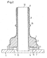
- FIG. 2 differs from that of Fig. 1 only in that the material the component 1 over the entire length of the tubular Component extends and the material of the component 2 to the end 12, the injection site 6 with the surface 7 of the ring member 11 facing away Collapse at the end of 12 This would be a theoretical one Leakage path in the axial direction around the entire component 2 around much longer than in the first embodiment of Fig. 1, except that a on the pipe socket clamped fluid line the outlet would prevent a fluid.
- the second embodiment has the same Advantages as the first embodiment, apart from a slightly thinner wall thickness of the component 2 in the end section 9, however, are also chosen could, as the wall thickness of the end portion 9 in the first embodiment of FIG. 1.
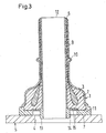
- the third embodiment of FIG. 3 differs from the second embodiment of FIG. 2 only in that in the second component 2 nor a third component 3 also from the injection point. 6 the second component 2 from - after injection of the Material of component 2 in the still plastic soul of the material of component 1 from that with the end 12 coincident injection point 6 - in the still plastic core of the material of component 2 injected became and thereby a substantial part of the Volume of the component 2 to close to the ring member 11th or the bottom 15 of the annular groove 14 fills.
- the material the component 3 is chosen so that it at least one of the properties strength, diffusion barrier ability and heat dimensional stability of the component elevated.
- the third component 3 predominantly one of the materials EVOH, PA, POM, PEN, PBT, PET, PBN, LCP, PPS, PPA, aliphatic polyketone and fluorothermoplastics.
- FIG. 4 differs of which according to FIGS. 1 and 2 substantially thereby, that the material of the component 1, which is at the same as in the embodiments of the Fig. 1 and 2, via the injection point 6 by the still plastic soul of the material of the component 2, which is also the same material as that of the component 2 of the embodiments according to FIGS. 1 and 2, up to the surface 7 through and also sprayed in the largest part of section 9 is.
- the largely diffusion-proof and more resistant Material of component 2 extends here Consequently, over most of the length of the tubular Component and component 1.
- Component 1 on the other hand continues to form the ring member 11, with the Material of the container 5 forms a fusion.
- This embodiment therefore has substantially the same advantages as shown in Fig. 2.
- the fifth embodiment of FIG. 5 differs from the third of Fig. 3 substantially only in that the third component 3 in the still plastic soul of the material of component 1 instead in the material of the component 2, as in the third Embodiment of the lying at the end 12 injection point 6 ago been injected after the Material of the component 1 over the 12 lying at the end Injection point 6 through the still plastic soul of Material of the component 2 through to the surface 7 therethrough was injected. Also in this fifth embodiment consist materials of components 1 to 3 each of the same materials as those of the components 1 to 3 of the third embodiment.
- the Fifth embodiment therefore has substantially the same advantages as the third embodiment.
- the first component 1 in all embodiments an electrically conductive additive.
- the components 2 and 3 can be an electric have conductive additive.
- this addition may be graphite particles, carbon fibers or iron particles, in particular fibrous Iron particles, act.
- Electrically conductive fibers simultaneously cause a Reinforcement of the material of the relevant component.
- conductive fiber parts or in addition can but also reinforcing particles of plastic, glass or mineral particles are used.
- tubular component or Stutzens can a component with a largely U or Trapezoidal cross section provided as a lid or plug be that for closing a blind opening or the like in the container.
- the injection point the second and optionally third component would then preferably in the middle of the outside of the component lie.
- another functional part molded on be, e.g. a retaining clip for a fluid line or an electrical cable.
Landscapes
- Engineering & Computer Science (AREA)
- Mechanical Engineering (AREA)
- Manufacturing & Machinery (AREA)
- General Engineering & Computer Science (AREA)
- Sustainable Development (AREA)
- Chemical & Material Sciences (AREA)
- Combustion & Propulsion (AREA)
- Transportation (AREA)
- Sustainable Energy (AREA)
- Life Sciences & Earth Sciences (AREA)
- Injection Moulding Of Plastics Or The Like (AREA)
- Cooling, Air Intake And Gas Exhaust, And Fuel Tank Arrangements In Propulsion Units (AREA)
- Branch Pipes, Bends, And The Like (AREA)
Abstract
Description
- Fig. 1
- einen Axialschnitt durch ein erfindungsgemäβes rohrförmiges Bauteil in einer Lage, in der es an einer Öffnung eines Behälters angeschweißt wird, um eine nicht dargestellte Fluidleitung mit der Behälteröffnung zu verbinden,
- Fig. 2
- ein zweites Ausführungsbeispiel eines erfindungsgemäßen Bauteils im Axialschnitt in der gleichen Lage wie das Bauteil nach Fig. 1,
- Fig. 3
- ein drittes Ausführungsbeispiel eines erfindungsgemäßen Bauteils im Axialschnitt in der gleichen Lage wie das Bauteil nach Fig. 1,
- Fig. 4
- ein viertes Ausführungsbeispiel eines erfindungsgemäßen Bauteils im Axialschnitt in der gleichen Lage wie das Bauteil nach Fig. 1 und
- Fig. 5
- ein fünftes Ausführungsbeispiel eines erfindungsgemäßen Bauteils im Axialschnitt in der gleichen Lage wie das Bauteil nach Fig. 1.
Claims (17)
- Bauteil zum Verbinden einer Fluidleitung mit einer Öffnung (4) eines überwiegend aus thermoplastischem Kunststoff, insbesondere Polyolefin, bestehenden Behälters (5) oder zum Verschließen der Öffnung (4), wobei das Bauteil wenigstens eine erste und eine zweite Komponente (1, 2) aus überwiegend thermoplastischem Kunststoff aufweist, das Material der ersten Komponente (1) mit dem Material des Behälters eine Schmelzverbindung durch Schweißen eingeht, aber keine hinreichende Diffusionssperrfähigkeit gegenüber Kohlenwasserstoffen, wie Benzin oder Dieselöl, aufweist und das Material der zweiten Komponente (2) eine erheblich höhere Diffusionssperrfähigkeit und geringere Quellfähigkeit gegenüber Kohlenwasserstoffen und eine höhere mechanische Festigkeit, auch nach einer Kohlenwasserstoff-Einwirkung, sowie eine höhere Formbeständigkeit in der Wärme als das Material der ersten Komponente (1) hat, dadurch gekennzeichnet, daß das Material der ersten Komponente (1) die zweite Komponente (2) wenigstens bis zu einer Einspritzstelle (6) einschließt, die einer am Behälter (5) anzuschweißenden Fläche (7) des Bauteils in möglichst großer bis größtmöglicher Entfernung abgekehrt ist und über die Material der zweiten Komponente (2) in die noch plastische Seele des Materials der ersten Komponente (1) eingespritzt worden ist.
- Bauteil nach Anspruch 1, dadurch gekennzeichnet, daß es weitgehend rohrförmig ist und das Material der zweiten Komponente (2) den größten Teil der Länge der Rohrwand ausfüllt.
- Bauteil nach Anspruch 2, dadurch gekennzeichnet, daß das Material der zweiten Komponente (2) einen der am Behälter anzuschweißenden Fläche (7) abgekehrten Endabschnitt (9) des rohrförmigen Bauteils bildet.
- Bauteil nach einem der Ansprüche 1 bis 3, dadurch gekennzeichnet, daß es weitgehend rohrförmig ist und sich das Material der zweiten Komponente (2) von einem die anzuschweißende Fläche (7) aufweisenden Ringteil (11) der ersten Komponente (1) bis zu dem dieser Fläche (7) abgekehrten Ende (12) des rohrförmigen Bauteils erstreckt:
- Bauteil nach einem der Ansprüche 1 bis 4, dadurch gekennzeichnet, daß die zweite Komponente (2) eine dritte Komponente (3) einschließt, durch die wenigstens eine der Eigenschaften Festigkeit, Diffusionssperrfähigkeit und Wärme-Formbeständigkeit des Bauteils erhöht wird.
- Bauteil zum Verbinden einer Fluidleitung mit einer Öffnung (4) eines überwiegend aus thermoplastischem Kunststoff, insbesondere Polyolefin, bestehenden Behälters (5) oder zum Verschließen der Öffnung (4), wobei das Bauteil wenigstens eine erste und eine zweite Komponente (1, 2) aus überwiegend thermoplastischem Kunststoff aufweist, das Material der ersten Komponente (1) mit dem Material des Behälters eine Schmelzverbindung durch Schweißen eingeht, aber keine hinreichende Diffusionssperrfähigkeit gegenüber Kohlenwasserstoffen, wie Benzin oder Dieselöl, aufweist und das Material der zweiten Komponente (2) eine erheblich höhere Diffusionssperrfähigkeit und geringere Quellfähigkeit gegenüber Kohlenwasserstoffen und eine höhere mechanische Festigkeit, auch nach einer Kohlenwasserstoff-Einwirkung, sowie eine höhere Formbeständigkeit in der Wärme als das Material der ersten Komponente (1) hat, dadurch gekennzeichnet, daß das Material der zweiten Komponente (2) die erste Komponente (1) wenigstens bis zu einer Einspritzstelle (6) einschließt, die einer am Behälter (5) anzuschweißenden Fläche (7) des Bauteils in möglichst großer bis größtmöglicher Entfernung abgekehrt ist und über die Material der ersten Komponente (1) durch die noch plastische Seele des Materials der zweiten Komponente (2) hindurch bis zu der am Behälter (5) anzuschweißenden Fläche (7) eingespritzt worden ist.
- Bauteil nach Anspruch 6, dadurch gekennzeichnet, daß es weitgehend rohrförmig ist und das Material der ersten Komponente (1) den größten Teil der Länge der Rohrwand ausfüllt.
- Bauteil nach Anspruch 7, dadurch gekennzeichnet, daß das Material der ersten Komponente (1) in einen der am Behälter anzuschweißenden Fläche (7) abgekehrten Endabschnitt (9) des rohrförmigen Bauteils eingespritzt ist.
- Bauteil nach einem der Ansprüche 6 bis 8, dadurch gekennzeichnet, daß es weitgehend rohrförmig ist und sich das Material der ersten Komponente (1) von einem die anzuschweißende Fläche (7) aufweisenden Ringteil (11) der ersten Komponente (1) bis zu dem dieser Fläche (7) abgekehrten Ende (12) des rohrförmigen Bauteils erstreckt.
- Bauteil nach Anspruch 4 oder 9, dadurch gekennzeichnet, daß das Ringteil (11) zwischen sich und einem koaxialen rohrförmigen Fortsatz (13) des Bauteils eine koaxiale Ringnut (14) begrenzt und die axiale Dicke des Ringteils (11) und die Tiefe der Ringnut (14) so gewählt sind, daß die Dicke nach dem Anschweißen jener Fläche (7) am Behälter (5) wegen der teilweise seitlich ausweichenden Schmelze des Ringteils (11) erheblich geringer ist, aber der Boden der Ringnut (14) weiterhin einen Abstand von dem Behälter (5) aufweist.
- Bauteil nach einem der Ansprüche 1 bis 10, dadurch gekennzeichnet, daß die erste Komponente (1) ein Polyolefin, insbesondere ein funktionalisiertes PE, aufweist, das mit dem Material des Behälters verschmelzbar ist.
- Bauteil nach einem der Ansprüche 1 bis 11, dadurch gekennzeichnet, daß die zweite Komponente (2) wenigstens eines der Materialien EVOH, PA, POM, PEN, PBT, PET, PBN, LCP, PPS, PPA, PP, aliphatisches Polyketon und Fluorthermoplast aufweist.
- Bauteil nach einem der Ansprüche 6 bis 9, dadurch gekennzeichnet, daß die erste Komponente (1) eine dritte Komponente (3) einschließt, durch die wenigstens eine der Eigenschaften Festigkeit, Diffusionssperrfähigkeit und Wärme-Formbeständigkeit des Bauteils erhöht wird.
- Bauteil nach Anspruch 5 oder 13, dadurch gekennzeichnet, daß die dritte Komponente (3) überwiegend eines der Materialien EVOH, PA, POM, PEN, PBT, PET, PBN, LCP, PPS, PPA, aliphatisches Polyketon und Fluorthermoplast aufweist.
- Bauteil nach einem der Ansprüche 1 bis 14, dadurch gekennzeichnet, daß wenigstens die erste Komponente (1) einen elektrisch leitfähigen Zusatz aufweist.
- Bauteil zum Verschließen der Öffnung des Behälters nach einem der Ansprüche 1 bis 15, dadurch gekennzeichnet, daß das Bauteil im Querschnitt weitgehend U- oder trapezförmig ist.
- Bauteil nach Anspruch 16, dadurch gekennzeichnet, daß wenigstens ein weiteres Funktionsteil an dem Bauteil angespritzt ist, z.B. ein Halterungs-Clip.
Priority Applications (4)
| Application Number | Priority Date | Filing Date | Title |
|---|---|---|---|
| EP20070006360 EP1829663B1 (de) | 2002-09-03 | 2003-05-28 | Bauteil zum Verbinden einer Fluidleitung mit einer Öffnung eines Kunststoffbehälters |
| US10/651,817 US7066498B2 (en) | 2002-09-03 | 2003-08-28 | Part for connecting a fluid line to an opening of a container comprising plastic material or for closing the opening |
| JP2003308855A JP2004263852A (ja) | 2002-09-03 | 2003-09-01 | プラスチック材料を含む容器の開口に流体路を接続する又は該開口を閉鎖する部品 |
| US11/418,432 US7631903B2 (en) | 2002-09-03 | 2006-05-04 | Part for connecting a fluid line to an opening of a container comprising plastic material or for closing the opening |
Applications Claiming Priority (2)
| Application Number | Priority Date | Filing Date | Title |
|---|---|---|---|
| DE2002141286 DE10241286B4 (de) | 2002-09-03 | 2002-09-03 | Bauteil zum Verbinden einer Fluidleitung mit einer Öffnung eines Kunststoff aufweisenden Behälters oder zum Verschließen der Öffnung |
| DE10241286 | 2002-09-03 |
Related Child Applications (1)
| Application Number | Title | Priority Date | Filing Date |
|---|---|---|---|
| EP20070006360 Division EP1829663B1 (de) | 2002-09-03 | 2003-05-28 | Bauteil zum Verbinden einer Fluidleitung mit einer Öffnung eines Kunststoffbehälters |
Publications (2)
| Publication Number | Publication Date |
|---|---|
| EP1396326A1 true EP1396326A1 (de) | 2004-03-10 |
| EP1396326B1 EP1396326B1 (de) | 2008-11-05 |
Family
ID=31502448
Family Applications (2)
| Application Number | Title | Priority Date | Filing Date |
|---|---|---|---|
| EP20030011989 Expired - Lifetime EP1396326B1 (de) | 2002-09-03 | 2003-05-28 | Bauteil zum Verbinden einer Fluidleitung mit einer Öffnung eines Kunststoffbehälters |
| EP20070006360 Expired - Lifetime EP1829663B1 (de) | 2002-09-03 | 2003-05-28 | Bauteil zum Verbinden einer Fluidleitung mit einer Öffnung eines Kunststoffbehälters |
Family Applications After (1)
| Application Number | Title | Priority Date | Filing Date |
|---|---|---|---|
| EP20070006360 Expired - Lifetime EP1829663B1 (de) | 2002-09-03 | 2003-05-28 | Bauteil zum Verbinden einer Fluidleitung mit einer Öffnung eines Kunststoffbehälters |
Country Status (4)
| Country | Link |
|---|---|
| US (2) | US7066498B2 (de) |
| EP (2) | EP1396326B1 (de) |
| JP (1) | JP2004263852A (de) |
| DE (2) | DE10241286B4 (de) |
Cited By (6)
| Publication number | Priority date | Publication date | Assignee | Title |
|---|---|---|---|---|
| EP1482233A2 (de) * | 2003-05-30 | 2004-12-01 | Rasmussen GmbH | Rohrartiger Stutzen |
| EP1632380A2 (de) * | 2004-09-04 | 2006-03-08 | Rasmussen GmbH | Bauteil mit rohrförmigem Abschnitt |
| FR2900092A1 (fr) * | 2006-04-21 | 2007-10-26 | Inergy Automotive Systems Res | Procede de fabrication d'un reservoir a carburant |
| WO2011082906A1 (de) * | 2009-12-15 | 2011-07-14 | Reinhard Feichtinger | Kraftstoffanbauteil und verfahren zur herstellung eines kraftstofftankanbauteils |
| AT511645A1 (de) * | 2011-07-05 | 2013-01-15 | Praher Kunststofftechnik Gmbh | Sandwich-spritzgiessverfahren und formteil mit einem im sandwich-spritzgiessverfahren hergestellten schichtverbund |
| EP3760908A1 (de) * | 2019-07-05 | 2021-01-06 | ContiTech Kühner GmbH & Cie. KG | Rohrleitung und abzweigelement |
Families Citing this family (23)
| Publication number | Priority date | Publication date | Assignee | Title |
|---|---|---|---|---|
| DE10161416A1 (de) * | 2001-12-13 | 2003-06-18 | Roth Werke Gmbh | Behälter, insbesondere Paletteninnenbehälter |
| DE10309275A1 (de) * | 2002-09-03 | 2004-03-25 | Rasmussen Gmbh | Kupplungsstück zum Verbinden eines Kraftstoffaufnahme- oder -abgabebauteils mit einer Fluidleitung und Verfahren zu dessen Herstellung |
| DE10241286B4 (de) * | 2002-09-03 | 2004-07-22 | Rasmussen Gmbh | Bauteil zum Verbinden einer Fluidleitung mit einer Öffnung eines Kunststoff aufweisenden Behälters oder zum Verschließen der Öffnung |
| GB0327043D0 (en) * | 2003-11-18 | 2004-04-07 | Rolls Royce Plc | A method of manufacturing an article by applying heat and pressure, a method of connecting a pipe to a sealed assembly and a connector for use therein |
| DE102005042678A1 (de) | 2004-12-24 | 2006-07-06 | Rasmussen Gmbh | Verfahren zur Herstellung eines Stutzens |
| JP4564858B2 (ja) * | 2005-02-08 | 2010-10-20 | 八千代工業株式会社 | 燃料タンクの構造 |
| US20070222213A1 (en) * | 2006-03-24 | 2007-09-27 | Florencia Andersen | Thermoplastic element for protection against corrosion in the thermofusion coupling of a thermoplastic tube |
| JP4991172B2 (ja) * | 2006-03-27 | 2012-08-01 | 株式会社ニフコ | 燃料タンク用コネクタ |
| US7669900B2 (en) * | 2006-07-14 | 2010-03-02 | Continental Automotive Systems Us, Inc. | Interface O-ring seal for low permeation flange of a fuel supply unit |
| WO2008024228A1 (en) * | 2006-08-21 | 2008-02-28 | Continental Automotive Systems Us, Inc. | Interface hose seal for low permeation flange of a fuel supply unit |
| DE102009016451B3 (de) * | 2009-04-04 | 2011-01-20 | Protechna S.A. | Entnahmearmatur mit einem Armaturengehäuse aus Kunststoff für Transport- und Lagerbehälter für Flüssigkeiten und Verfahren zur Herstellung des elektrisch geerdeten Anschlussflansches zur Befestigung der Entnahmearmatur an dem Entleerstutzen des Innenbehälters des Transport- und Lagerbehälters |
| CN101612776B (zh) * | 2009-07-14 | 2012-06-27 | 亚普汽车部件股份有限公司 | 塑料燃油箱接口的专用模具 |
| DE102009050808A1 (de) * | 2009-10-27 | 2011-04-28 | Bayerische Motoren Werke Aktiengesellschaft | Kraftstoff-Einfüllrohr |
| US20110284126A1 (en) * | 2010-04-20 | 2011-11-24 | Stant Usa Corp. | Mount for inlet check valve |
| US8550287B2 (en) * | 2011-12-13 | 2013-10-08 | Ford Global Technologies, Llc | Sealing a fuel tank against hydrocarbon permeation |
| WO2014008318A1 (en) | 2012-07-02 | 2014-01-09 | Norma U.S. Holding Llc | Fuel line connector and method of making |
| US9248587B2 (en) * | 2012-07-05 | 2016-02-02 | General Electric Company | Apparatus for manufacturing a flanged composite component and methods of manufacturing the same |
| JP6442301B2 (ja) * | 2015-01-23 | 2018-12-19 | ユニプレス株式会社 | 自動車の金属製燃料タンクの給油管取付け構造 |
| EP3127735B1 (de) * | 2015-08-07 | 2017-07-05 | Magna Steyr Fuel Systems GesmbH | Tankeinfüllstutzen für ein kraftfahrzeug mit verbesserter diffusionsfestigkeit |
| US11149883B2 (en) | 2016-06-24 | 2021-10-19 | Eaton Intelligent Power Limited | Fluid couplings, systems, and methods |
| US10883640B2 (en) | 2016-06-24 | 2021-01-05 | Eaton Intelligent Power Limited | Fluid couplings, systems, and methods |
| FR3077013B1 (fr) * | 2018-01-24 | 2023-12-15 | Aptar France Sas | Dispositif de distribution de produit fluide. |
| CN111255955A (zh) * | 2018-11-30 | 2020-06-09 | 上海英泰塑胶股份有限公司 | 内嵌增强芯件的耐高压注塑管件 |
Citations (7)
| Publication number | Priority date | Publication date | Assignee | Title |
|---|---|---|---|---|
| US5798048A (en) * | 1995-05-27 | 1998-08-25 | Huels Aktiengesellschaft | Multilayer plastic fuel filter having antistatic properties |
| EP1063078A2 (de) * | 1999-06-21 | 2000-12-27 | Rasmussen GmbH | Verfahren zur Herstellung eines Stutzens |
| EP1095962A2 (de) * | 1999-10-27 | 2001-05-02 | Ticona GmbH | Verschweissbare Bauteile aus Polyacetal |
| DE10048973A1 (de) * | 1999-09-27 | 2001-07-05 | Heiner Becker | Kunststofffitting sowie Verfahren zu dessen Herstellung und Vorrichtung zur Herstellung eines Kunststoffkörpers |
| US20010050478A1 (en) * | 2000-05-26 | 2001-12-13 | Degussa-Huels Aktiengesellschaft | Plastic molding having two or more layers and antistatic properties |
| DE10062997A1 (de) * | 2000-12-16 | 2002-07-18 | Rasmussen Gmbh | Rohrartiger Stutzen |
| EP1233174A2 (de) * | 2001-02-15 | 2002-08-21 | Delphi Technologies, Inc. | Verbundkraftstoffleitung mit integrierter Dämpfung von Druckschwingungen und einer kospritzgegossenen permeationsbeständigen Schicht und deren Herstellungsverfahren |
Family Cites Families (27)
| Publication number | Priority date | Publication date | Assignee | Title |
|---|---|---|---|---|
| US653280A (en) * | 1900-03-10 | 1900-07-10 | Friedrich Wilhelm Barthels | Flanged tube. |
| US1978609A (en) * | 1933-06-24 | 1934-10-30 | Smith Corp A O | Welded manway for pressure vessels |
| US2922932A (en) * | 1956-06-25 | 1960-01-26 | Sessions Clock Co | Magnetic coils |
| US4047061A (en) * | 1973-03-16 | 1977-09-06 | P. R. Mallory & Co., Inc. | Coil protector for permanent magnet synchronous motor |
| US4613168A (en) * | 1982-03-04 | 1986-09-23 | Avon Industrial Polymers Limited | Method of making branches in hoses |
| DE3828696A1 (de) * | 1988-08-24 | 1990-03-01 | Bayer Ag | Elastomermodifizierte, kohlenstoffhaltige polyarylensulfidabmischungen |
| DE19535413C1 (de) * | 1995-09-23 | 1996-10-02 | Rasmussen Gmbh | Rohrartiger Stutzen |
| US5951059A (en) * | 1996-07-24 | 1999-09-14 | Tokai Rubber Industries Ltd. | Tube connector device having connector holder made of elastomer |
| US5837180A (en) * | 1997-02-05 | 1998-11-17 | Fluoroware, Inc. | Composite plastic sanitary fitting |
| US5912518A (en) * | 1997-10-22 | 1999-06-15 | Misik; Michael F. | Motor coil assembly |
| CA2334149C (en) * | 2000-02-03 | 2005-05-10 | Stant Manufacturing Inc. | Weldable mount for fuel systems component |
| US6652699B1 (en) * | 2000-02-17 | 2003-11-25 | Salflex Polymers Ltd. | Flanged member with barrier layer |
| JP3824212B2 (ja) * | 2000-11-17 | 2006-09-20 | 豊田合成株式会社 | 燃料タンク付設弁 |
| JP3994662B2 (ja) * | 2000-03-30 | 2007-10-24 | 豊田合成株式会社 | 燃料遮断弁 |
| US6289915B1 (en) * | 2000-06-06 | 2001-09-18 | Visteon Global Technologies, Inc. | Permeation and leak preventative design for fuel tank attachments |
| JP3777290B2 (ja) * | 2000-06-14 | 2006-05-24 | 日本電産サンキョー株式会社 | モータ |
| JP3914733B2 (ja) * | 2000-11-02 | 2007-05-16 | 株式会社ニフコ | 燃料タンク用コネクタ |
| DE10056974C1 (de) * | 2000-11-17 | 2002-01-17 | Rasmussen Gmbh | Rohrartiger Stutzen |
| JP3893987B2 (ja) * | 2001-03-16 | 2007-03-14 | 東海ゴム工業株式会社 | タンク接合部品、リング状樹脂成形品の成形方法 |
| US6612324B2 (en) * | 2001-03-19 | 2003-09-02 | Saturn Electronics & Engineering, Inc. | Fill limit vapor valve with variable vapor venting capability |
| US6662820B2 (en) * | 2001-12-06 | 2003-12-16 | Stant Manufacturing Inc. | Weldable mount for fuel system component |
| JP3821224B2 (ja) * | 2002-03-15 | 2006-09-13 | 日産自動車株式会社 | 燃料封入容器と溶着部品の溶着方法 |
| JP3909837B2 (ja) * | 2002-08-23 | 2007-04-25 | 豊田合成株式会社 | 燃料タンクの燃料流出規制装置 |
| DE10309275A1 (de) * | 2002-09-03 | 2004-03-25 | Rasmussen Gmbh | Kupplungsstück zum Verbinden eines Kraftstoffaufnahme- oder -abgabebauteils mit einer Fluidleitung und Verfahren zu dessen Herstellung |
| DE10241286B4 (de) * | 2002-09-03 | 2004-07-22 | Rasmussen Gmbh | Bauteil zum Verbinden einer Fluidleitung mit einer Öffnung eines Kunststoff aufweisenden Behälters oder zum Verschließen der Öffnung |
| US20040155457A1 (en) * | 2003-02-12 | 2004-08-12 | Maersk Medical A/S | Connecting element comprising a first body and a method for injection moulding a connecting element |
| US6840264B1 (en) * | 2003-08-13 | 2005-01-11 | Visteon Global Technologies, Inc. | Fuel tank venting system for reduced fuel permeation |
-
2002
- 2002-09-03 DE DE2002141286 patent/DE10241286B4/de not_active Expired - Lifetime
-
2003
- 2003-05-28 EP EP20030011989 patent/EP1396326B1/de not_active Expired - Lifetime
- 2003-05-28 EP EP20070006360 patent/EP1829663B1/de not_active Expired - Lifetime
- 2003-05-28 DE DE50310737T patent/DE50310737D1/de not_active Expired - Lifetime
- 2003-08-28 US US10/651,817 patent/US7066498B2/en not_active Expired - Lifetime
- 2003-09-01 JP JP2003308855A patent/JP2004263852A/ja active Pending
-
2006
- 2006-05-04 US US11/418,432 patent/US7631903B2/en active Active
Patent Citations (7)
| Publication number | Priority date | Publication date | Assignee | Title |
|---|---|---|---|---|
| US5798048A (en) * | 1995-05-27 | 1998-08-25 | Huels Aktiengesellschaft | Multilayer plastic fuel filter having antistatic properties |
| EP1063078A2 (de) * | 1999-06-21 | 2000-12-27 | Rasmussen GmbH | Verfahren zur Herstellung eines Stutzens |
| DE10048973A1 (de) * | 1999-09-27 | 2001-07-05 | Heiner Becker | Kunststofffitting sowie Verfahren zu dessen Herstellung und Vorrichtung zur Herstellung eines Kunststoffkörpers |
| EP1095962A2 (de) * | 1999-10-27 | 2001-05-02 | Ticona GmbH | Verschweissbare Bauteile aus Polyacetal |
| US20010050478A1 (en) * | 2000-05-26 | 2001-12-13 | Degussa-Huels Aktiengesellschaft | Plastic molding having two or more layers and antistatic properties |
| DE10062997A1 (de) * | 2000-12-16 | 2002-07-18 | Rasmussen Gmbh | Rohrartiger Stutzen |
| EP1233174A2 (de) * | 2001-02-15 | 2002-08-21 | Delphi Technologies, Inc. | Verbundkraftstoffleitung mit integrierter Dämpfung von Druckschwingungen und einer kospritzgegossenen permeationsbeständigen Schicht und deren Herstellungsverfahren |
Cited By (11)
| Publication number | Priority date | Publication date | Assignee | Title |
|---|---|---|---|---|
| EP1482233A2 (de) * | 2003-05-30 | 2004-12-01 | Rasmussen GmbH | Rohrartiger Stutzen |
| EP1482233A3 (de) * | 2003-05-30 | 2007-05-23 | Rasmussen GmbH | Rohrartiger Stutzen |
| EP1632380A2 (de) * | 2004-09-04 | 2006-03-08 | Rasmussen GmbH | Bauteil mit rohrförmigem Abschnitt |
| EP1632380A3 (de) * | 2004-09-04 | 2007-02-14 | Rasmussen GmbH | Bauteil mit rohrförmigem Abschnitt |
| US8394472B2 (en) | 2004-09-04 | 2013-03-12 | Norma Germany Gmbh | Structural component with tubular section |
| FR2900092A1 (fr) * | 2006-04-21 | 2007-10-26 | Inergy Automotive Systems Res | Procede de fabrication d'un reservoir a carburant |
| WO2007122185A1 (en) * | 2006-04-21 | 2007-11-01 | Inergy Automotive Systems Research (Société Anonyme) | Method of manufacturing a fuel tank |
| WO2011082906A1 (de) * | 2009-12-15 | 2011-07-14 | Reinhard Feichtinger | Kraftstoffanbauteil und verfahren zur herstellung eines kraftstofftankanbauteils |
| AT511645A1 (de) * | 2011-07-05 | 2013-01-15 | Praher Kunststofftechnik Gmbh | Sandwich-spritzgiessverfahren und formteil mit einem im sandwich-spritzgiessverfahren hergestellten schichtverbund |
| AT511645B1 (de) * | 2011-07-05 | 2015-05-15 | Praher Kunststofftechnik Gmbh | Sandwich-spritzgiessverfahren und formteil mit einem im sandwich-spritzgiessverfahren hergestellten schichtverbund |
| EP3760908A1 (de) * | 2019-07-05 | 2021-01-06 | ContiTech Kühner GmbH & Cie. KG | Rohrleitung und abzweigelement |
Also Published As
| Publication number | Publication date |
|---|---|
| EP1829663A1 (de) | 2007-09-05 |
| DE10241286A1 (de) | 2004-03-18 |
| US20060197341A1 (en) | 2006-09-07 |
| US7066498B2 (en) | 2006-06-27 |
| US7631903B2 (en) | 2009-12-15 |
| DE50310737D1 (de) | 2008-12-18 |
| DE10241286B4 (de) | 2004-07-22 |
| JP2004263852A (ja) | 2004-09-24 |
| US20040051305A1 (en) | 2004-03-18 |
| EP1829663B1 (de) | 2013-05-15 |
| EP1396326B1 (de) | 2008-11-05 |
Similar Documents
| Publication | Publication Date | Title |
|---|---|---|
| DE10241286B4 (de) | Bauteil zum Verbinden einer Fluidleitung mit einer Öffnung eines Kunststoff aufweisenden Behälters oder zum Verschließen der Öffnung | |
| EP2030755B1 (de) | Verfahren zur Herstellung eines Stutzens | |
| DE102006005828B4 (de) | Anschlussrohr für einen Kraftstofftank | |
| EP1852390B1 (de) | Absperrorgan für einen Behälter, insbesondere Palettenbehälter | |
| EP1063078B1 (de) | Verfahren zur Herstellung eines Stutzens | |
| DE2555017A1 (de) | Roehrfoermiges gebilde zum transport fluessiger oder gasfoermiger medien, insbesondere bei hohen temperaturen und hohem druck | |
| DE102006005529A1 (de) | Kunststoffbehälter mit wenigstens einer Elektrode aus elektrisch leitfähigem Kunststoff | |
| DE102005050564A1 (de) | Schweißverbinder für einen Kraftstofftank | |
| DE102010062985A1 (de) | Flüssigkeitsentnahmemodul, Flüssigkeitstank | |
| EP1632380B1 (de) | Bauteil mit rohrförmigem Abschnitt | |
| EP1396327B1 (de) | Kupplungsstück zum Verbinden eines Kraftstofftanks mit einer Fluidleitung und Verfahren zu dessen Herstellung | |
| EP2129708B1 (de) | Kraftstofftankanbauteil und verfahren zur herstellung eines kraftstofftankanbauteils | |
| DE10324471B3 (de) | Rohrartiger Stutzen | |
| DE4238682A1 (de) | Infusionsflasche | |
| DE10062997A1 (de) | Rohrartiger Stutzen | |
| EP2512857B1 (de) | Kraftstoffttankanbauteil und verfahren zur herstellung eines kraftstofftankanbauteils | |
| EP1509418B1 (de) | Einfüllrohr | |
| DE10056974C1 (de) | Rohrartiger Stutzen | |
| DE19951670A1 (de) | Verschweißbare Bauteile aus Polyacetal | |
| EP0537377B1 (de) | Rohrverbindung | |
| EP1288053A2 (de) | Kraftstoffbehälter aus Kunststoff | |
| WO2011073146A1 (de) | Kraftstoffleitung und kraftstofftanksystem | |
| DE7509377U (de) | Endpoldurchführung für Akkumulatoren |
Legal Events
| Date | Code | Title | Description |
|---|---|---|---|
| PUAI | Public reference made under article 153(3) epc to a published international application that has entered the european phase |
Free format text: ORIGINAL CODE: 0009012 |
|
| AK | Designated contracting states |
Kind code of ref document: A1 Designated state(s): AT BE BG CH CY CZ DE DK EE ES FI FR GB GR HU IE IT LI LU MC NL PT RO SE SI SK TR |
|
| AX | Request for extension of the european patent |
Extension state: AL LT LV MK |
|
| 17P | Request for examination filed |
Effective date: 20040429 |
|
| 17Q | First examination report despatched |
Effective date: 20040519 |
|
| AKX | Designation fees paid |
Designated state(s): DE FR GB |
|
| 17Q | First examination report despatched |
Effective date: 20040519 |
|
| RAP1 | Party data changed (applicant data changed or rights of an application transferred) |
Owner name: NORMA GERMANY GMBH |
|
| GRAP | Despatch of communication of intention to grant a patent |
Free format text: ORIGINAL CODE: EPIDOSNIGR1 |
|
| GRAS | Grant fee paid |
Free format text: ORIGINAL CODE: EPIDOSNIGR3 |
|
| GRAA | (expected) grant |
Free format text: ORIGINAL CODE: 0009210 |
|
| AK | Designated contracting states |
Kind code of ref document: B1 Designated state(s): DE FR GB |
|
| REG | Reference to a national code |
Ref country code: GB Ref legal event code: FG4D Free format text: NOT ENGLISH |
|
| REF | Corresponds to: |
Ref document number: 50310737 Country of ref document: DE Date of ref document: 20081218 Kind code of ref document: P |
|
| PLBE | No opposition filed within time limit |
Free format text: ORIGINAL CODE: 0009261 |
|
| STAA | Information on the status of an ep patent application or granted ep patent |
Free format text: STATUS: NO OPPOSITION FILED WITHIN TIME LIMIT |
|
| 26N | No opposition filed |
Effective date: 20090806 |
|
| REG | Reference to a national code |
Ref country code: FR Ref legal event code: PLFP Year of fee payment: 13 |
|
| REG | Reference to a national code |
Ref country code: DE Ref legal event code: R082 Ref document number: 50310737 Country of ref document: DE Representative=s name: PATENTANWAELTE OLBRICHT, BUCHHOLD, KEULERTZ PA, DE |
|
| REG | Reference to a national code |
Ref country code: FR Ref legal event code: PLFP Year of fee payment: 14 |
|
| REG | Reference to a national code |
Ref country code: FR Ref legal event code: PLFP Year of fee payment: 15 |
|
| REG | Reference to a national code |
Ref country code: FR Ref legal event code: PLFP Year of fee payment: 16 |
|
| PGFP | Annual fee paid to national office [announced via postgrant information from national office to epo] |
Ref country code: GB Payment date: 20220527 Year of fee payment: 20 Ref country code: FR Payment date: 20220525 Year of fee payment: 20 Ref country code: DE Payment date: 20220527 Year of fee payment: 20 |
|
| REG | Reference to a national code |
Ref country code: DE Ref legal event code: R071 Ref document number: 50310737 Country of ref document: DE |
|
| REG | Reference to a national code |
Ref country code: GB Ref legal event code: PE20 Expiry date: 20230527 |
|
| PG25 | Lapsed in a contracting state [announced via postgrant information from national office to epo] |
Ref country code: GB Free format text: LAPSE BECAUSE OF EXPIRATION OF PROTECTION Effective date: 20230527 |