US6840264B1 - Fuel tank venting system for reduced fuel permeation - Google Patents
Fuel tank venting system for reduced fuel permeation Download PDFInfo
- Publication number
- US6840264B1 US6840264B1 US10/640,600 US64060003A US6840264B1 US 6840264 B1 US6840264 B1 US 6840264B1 US 64060003 A US64060003 A US 64060003A US 6840264 B1 US6840264 B1 US 6840264B1
- Authority
- US
- United States
- Prior art keywords
- tank
- venting
- valve
- assembly
- outer layer
- Prior art date
- Legal status (The legal status is an assumption and is not a legal conclusion. Google has not performed a legal analysis and makes no representation as to the accuracy of the status listed.)
- Expired - Lifetime
Links
Images


Classifications
-
- B—PERFORMING OPERATIONS; TRANSPORTING
- B29—WORKING OF PLASTICS; WORKING OF SUBSTANCES IN A PLASTIC STATE IN GENERAL
- B29C—SHAPING OR JOINING OF PLASTICS; SHAPING OF MATERIAL IN A PLASTIC STATE, NOT OTHERWISE PROVIDED FOR; AFTER-TREATMENT OF THE SHAPED PRODUCTS, e.g. REPAIRING
- B29C65/00—Joining or sealing of preformed parts, e.g. welding of plastics materials; Apparatus therefor
- B29C65/02—Joining or sealing of preformed parts, e.g. welding of plastics materials; Apparatus therefor by heating, with or without pressure
-
- B—PERFORMING OPERATIONS; TRANSPORTING
- B29—WORKING OF PLASTICS; WORKING OF SUBSTANCES IN A PLASTIC STATE IN GENERAL
- B29C—SHAPING OR JOINING OF PLASTICS; SHAPING OF MATERIAL IN A PLASTIC STATE, NOT OTHERWISE PROVIDED FOR; AFTER-TREATMENT OF THE SHAPED PRODUCTS, e.g. REPAIRING
- B29C66/00—General aspects of processes or apparatus for joining preformed parts
- B29C66/01—General aspects dealing with the joint area or with the area to be joined
- B29C66/05—Particular design of joint configurations
- B29C66/10—Particular design of joint configurations particular design of the joint cross-sections
- B29C66/11—Joint cross-sections comprising a single joint-segment, i.e. one of the parts to be joined comprising a single joint-segment in the joint cross-section
- B29C66/112—Single lapped joints
-
- B—PERFORMING OPERATIONS; TRANSPORTING
- B29—WORKING OF PLASTICS; WORKING OF SUBSTANCES IN A PLASTIC STATE IN GENERAL
- B29C—SHAPING OR JOINING OF PLASTICS; SHAPING OF MATERIAL IN A PLASTIC STATE, NOT OTHERWISE PROVIDED FOR; AFTER-TREATMENT OF THE SHAPED PRODUCTS, e.g. REPAIRING
- B29C66/00—General aspects of processes or apparatus for joining preformed parts
- B29C66/01—General aspects dealing with the joint area or with the area to be joined
- B29C66/05—Particular design of joint configurations
- B29C66/10—Particular design of joint configurations particular design of the joint cross-sections
- B29C66/13—Single flanged joints; Fin-type joints; Single hem joints; Edge joints; Interpenetrating fingered joints; Other specific particular designs of joint cross-sections not provided for in groups B29C66/11 - B29C66/12
- B29C66/131—Single flanged joints, i.e. one of the parts to be joined being rigid and flanged in the joint area
-
- B—PERFORMING OPERATIONS; TRANSPORTING
- B29—WORKING OF PLASTICS; WORKING OF SUBSTANCES IN A PLASTIC STATE IN GENERAL
- B29C—SHAPING OR JOINING OF PLASTICS; SHAPING OF MATERIAL IN A PLASTIC STATE, NOT OTHERWISE PROVIDED FOR; AFTER-TREATMENT OF THE SHAPED PRODUCTS, e.g. REPAIRING
- B29C66/00—General aspects of processes or apparatus for joining preformed parts
- B29C66/50—General aspects of joining tubular articles; General aspects of joining long products, i.e. bars or profiled elements; General aspects of joining single elements to tubular articles, hollow articles or bars; General aspects of joining several hollow-preforms to form hollow or tubular articles
- B29C66/51—Joining tubular articles, profiled elements or bars; Joining single elements to tubular articles, hollow articles or bars; Joining several hollow-preforms to form hollow or tubular articles
- B29C66/53—Joining single elements to tubular articles, hollow articles or bars
- B29C66/532—Joining single elements to the wall of tubular articles, hollow articles or bars
- B29C66/5324—Joining single elements to the wall of tubular articles, hollow articles or bars said single elements being substantially annular, i.e. of finite length
- B29C66/53245—Joining single elements to the wall of tubular articles, hollow articles or bars said single elements being substantially annular, i.e. of finite length said articles being hollow
- B29C66/53246—Joining single elements to the wall of tubular articles, hollow articles or bars said single elements being substantially annular, i.e. of finite length said articles being hollow said single elements being spouts, e.g. joining spouts to containers
-
- B—PERFORMING OPERATIONS; TRANSPORTING
- B29—WORKING OF PLASTICS; WORKING OF SUBSTANCES IN A PLASTIC STATE IN GENERAL
- B29C—SHAPING OR JOINING OF PLASTICS; SHAPING OF MATERIAL IN A PLASTIC STATE, NOT OTHERWISE PROVIDED FOR; AFTER-TREATMENT OF THE SHAPED PRODUCTS, e.g. REPAIRING
- B29C66/00—General aspects of processes or apparatus for joining preformed parts
- B29C66/70—General aspects of processes or apparatus for joining preformed parts characterised by the composition, physical properties or the structure of the material of the parts to be joined; Joining with non-plastics material
- B29C66/72—General aspects of processes or apparatus for joining preformed parts characterised by the composition, physical properties or the structure of the material of the parts to be joined; Joining with non-plastics material characterised by the structure of the material of the parts to be joined
- B29C66/723—General aspects of processes or apparatus for joining preformed parts characterised by the composition, physical properties or the structure of the material of the parts to be joined; Joining with non-plastics material characterised by the structure of the material of the parts to be joined being multi-layered
- B29C66/7234—General aspects of processes or apparatus for joining preformed parts characterised by the composition, physical properties or the structure of the material of the parts to be joined; Joining with non-plastics material characterised by the structure of the material of the parts to be joined being multi-layered comprising a barrier layer
-
- B—PERFORMING OPERATIONS; TRANSPORTING
- B29—WORKING OF PLASTICS; WORKING OF SUBSTANCES IN A PLASTIC STATE IN GENERAL
- B29C—SHAPING OR JOINING OF PLASTICS; SHAPING OF MATERIAL IN A PLASTIC STATE, NOT OTHERWISE PROVIDED FOR; AFTER-TREATMENT OF THE SHAPED PRODUCTS, e.g. REPAIRING
- B29C66/00—General aspects of processes or apparatus for joining preformed parts
- B29C66/70—General aspects of processes or apparatus for joining preformed parts characterised by the composition, physical properties or the structure of the material of the parts to be joined; Joining with non-plastics material
- B29C66/73—General aspects of processes or apparatus for joining preformed parts characterised by the composition, physical properties or the structure of the material of the parts to be joined; Joining with non-plastics material characterised by the intensive physical properties of the material of the parts to be joined, by the optical properties of the material of the parts to be joined, by the extensive physical properties of the parts to be joined, by the state of the material of the parts to be joined or by the material of the parts to be joined being a thermoplastic or a thermoset
- B29C66/731—General aspects of processes or apparatus for joining preformed parts characterised by the composition, physical properties or the structure of the material of the parts to be joined; Joining with non-plastics material characterised by the intensive physical properties of the material of the parts to be joined, by the optical properties of the material of the parts to be joined, by the extensive physical properties of the parts to be joined, by the state of the material of the parts to be joined or by the material of the parts to be joined being a thermoplastic or a thermoset characterised by the intensive physical properties of the material of the parts to be joined
- B29C66/7311—Thermal properties
- B29C66/73111—Thermal expansion coefficient
-
- B—PERFORMING OPERATIONS; TRANSPORTING
- B60—VEHICLES IN GENERAL
- B60K—ARRANGEMENT OR MOUNTING OF PROPULSION UNITS OR OF TRANSMISSIONS IN VEHICLES; ARRANGEMENT OR MOUNTING OF PLURAL DIVERSE PRIME-MOVERS IN VEHICLES; AUXILIARY DRIVES FOR VEHICLES; INSTRUMENTATION OR DASHBOARDS FOR VEHICLES; ARRANGEMENTS IN CONNECTION WITH COOLING, AIR INTAKE, GAS EXHAUST OR FUEL SUPPLY OF PROPULSION UNITS IN VEHICLES
- B60K15/00—Arrangement in connection with fuel supply of combustion engines or other fuel consuming energy converters, e.g. fuel cells; Mounting or construction of fuel tanks
- B60K15/03—Fuel tanks
- B60K15/035—Fuel tanks characterised by venting means
- B60K15/03519—Valve arrangements in the vent line
-
- B—PERFORMING OPERATIONS; TRANSPORTING
- B29—WORKING OF PLASTICS; WORKING OF SUBSTANCES IN A PLASTIC STATE IN GENERAL
- B29C—SHAPING OR JOINING OF PLASTICS; SHAPING OF MATERIAL IN A PLASTIC STATE, NOT OTHERWISE PROVIDED FOR; AFTER-TREATMENT OF THE SHAPED PRODUCTS, e.g. REPAIRING
- B29C66/00—General aspects of processes or apparatus for joining preformed parts
- B29C66/01—General aspects dealing with the joint area or with the area to be joined
- B29C66/05—Particular design of joint configurations
- B29C66/20—Particular design of joint configurations particular design of the joint lines, e.g. of the weld lines
- B29C66/24—Particular design of joint configurations particular design of the joint lines, e.g. of the weld lines said joint lines being closed or non-straight
- B29C66/242—Particular design of joint configurations particular design of the joint lines, e.g. of the weld lines said joint lines being closed or non-straight said joint lines being closed, i.e. forming closed contours
- B29C66/2422—Particular design of joint configurations particular design of the joint lines, e.g. of the weld lines said joint lines being closed or non-straight said joint lines being closed, i.e. forming closed contours being circular, oval or elliptical
- B29C66/24221—Particular design of joint configurations particular design of the joint lines, e.g. of the weld lines said joint lines being closed or non-straight said joint lines being closed, i.e. forming closed contours being circular, oval or elliptical being circular
-
- B—PERFORMING OPERATIONS; TRANSPORTING
- B29—WORKING OF PLASTICS; WORKING OF SUBSTANCES IN A PLASTIC STATE IN GENERAL
- B29C—SHAPING OR JOINING OF PLASTICS; SHAPING OF MATERIAL IN A PLASTIC STATE, NOT OTHERWISE PROVIDED FOR; AFTER-TREATMENT OF THE SHAPED PRODUCTS, e.g. REPAIRING
- B29C66/00—General aspects of processes or apparatus for joining preformed parts
- B29C66/70—General aspects of processes or apparatus for joining preformed parts characterised by the composition, physical properties or the structure of the material of the parts to be joined; Joining with non-plastics material
- B29C66/71—General aspects of processes or apparatus for joining preformed parts characterised by the composition, physical properties or the structure of the material of the parts to be joined; Joining with non-plastics material characterised by the composition of the plastics material of the parts to be joined
-
- B—PERFORMING OPERATIONS; TRANSPORTING
- B29—WORKING OF PLASTICS; WORKING OF SUBSTANCES IN A PLASTIC STATE IN GENERAL
- B29K—INDEXING SCHEME ASSOCIATED WITH SUBCLASSES B29B, B29C OR B29D, RELATING TO MOULDING MATERIALS OR TO MATERIALS FOR MOULDS, REINFORCEMENTS, FILLERS OR PREFORMED PARTS, e.g. INSERTS
- B29K2023/00—Use of polyalkenes or derivatives thereof as moulding material
- B29K2023/04—Polymers of ethylene
- B29K2023/06—PE, i.e. polyethylene
- B29K2023/0608—PE, i.e. polyethylene characterised by its density
- B29K2023/065—HDPE, i.e. high density polyethylene
-
- B—PERFORMING OPERATIONS; TRANSPORTING
- B29—WORKING OF PLASTICS; WORKING OF SUBSTANCES IN A PLASTIC STATE IN GENERAL
- B29K—INDEXING SCHEME ASSOCIATED WITH SUBCLASSES B29B, B29C OR B29D, RELATING TO MOULDING MATERIALS OR TO MATERIALS FOR MOULDS, REINFORCEMENTS, FILLERS OR PREFORMED PARTS, e.g. INSERTS
- B29K2023/00—Use of polyalkenes or derivatives thereof as moulding material
- B29K2023/04—Polymers of ethylene
- B29K2023/08—Copolymers of ethylene
- B29K2023/086—EVOH, i.e. ethylene vinyl alcohol copolymer
-
- B—PERFORMING OPERATIONS; TRANSPORTING
- B29—WORKING OF PLASTICS; WORKING OF SUBSTANCES IN A PLASTIC STATE IN GENERAL
- B29L—INDEXING SCHEME ASSOCIATED WITH SUBCLASS B29C, RELATING TO PARTICULAR ARTICLES
- B29L2031/00—Other particular articles
- B29L2031/712—Containers; Packaging elements or accessories, Packages
- B29L2031/7172—Fuel tanks, jerry cans
-
- B—PERFORMING OPERATIONS; TRANSPORTING
- B60—VEHICLES IN GENERAL
- B60K—ARRANGEMENT OR MOUNTING OF PROPULSION UNITS OR OF TRANSMISSIONS IN VEHICLES; ARRANGEMENT OR MOUNTING OF PLURAL DIVERSE PRIME-MOVERS IN VEHICLES; AUXILIARY DRIVES FOR VEHICLES; INSTRUMENTATION OR DASHBOARDS FOR VEHICLES; ARRANGEMENTS IN CONNECTION WITH COOLING, AIR INTAKE, GAS EXHAUST OR FUEL SUPPLY OF PROPULSION UNITS IN VEHICLES
- B60K15/00—Arrangement in connection with fuel supply of combustion engines or other fuel consuming energy converters, e.g. fuel cells; Mounting or construction of fuel tanks
- B60K15/03—Fuel tanks
- B60K2015/03032—Manufacturing of fuel tanks
- B60K2015/03046—Manufacturing of fuel tanks made from more than one layer
-
- B—PERFORMING OPERATIONS; TRANSPORTING
- B60—VEHICLES IN GENERAL
- B60K—ARRANGEMENT OR MOUNTING OF PROPULSION UNITS OR OF TRANSMISSIONS IN VEHICLES; ARRANGEMENT OR MOUNTING OF PLURAL DIVERSE PRIME-MOVERS IN VEHICLES; AUXILIARY DRIVES FOR VEHICLES; INSTRUMENTATION OR DASHBOARDS FOR VEHICLES; ARRANGEMENTS IN CONNECTION WITH COOLING, AIR INTAKE, GAS EXHAUST OR FUEL SUPPLY OF PROPULSION UNITS IN VEHICLES
- B60K15/00—Arrangement in connection with fuel supply of combustion engines or other fuel consuming energy converters, e.g. fuel cells; Mounting or construction of fuel tanks
- B60K15/03—Fuel tanks
- B60K2015/03328—Arrangements or special measures related to fuel tanks or fuel handling
- B60K2015/03447—Arrangements or special measures related to fuel tanks or fuel handling for improving the sealing
-
- Y—GENERAL TAGGING OF NEW TECHNOLOGICAL DEVELOPMENTS; GENERAL TAGGING OF CROSS-SECTIONAL TECHNOLOGIES SPANNING OVER SEVERAL SECTIONS OF THE IPC; TECHNICAL SUBJECTS COVERED BY FORMER USPC CROSS-REFERENCE ART COLLECTIONS [XRACs] AND DIGESTS
- Y10—TECHNICAL SUBJECTS COVERED BY FORMER USPC
- Y10T—TECHNICAL SUBJECTS COVERED BY FORMER US CLASSIFICATION
- Y10T137/00—Fluid handling
- Y10T137/2931—Diverse fluid containing pressure systems
- Y10T137/3003—Fluid separating traps or vents
- Y10T137/3084—Discriminating outlet for gas
- Y10T137/309—Fluid sensing valve
- Y10T137/3099—Float responsive
-
- Y—GENERAL TAGGING OF NEW TECHNOLOGICAL DEVELOPMENTS; GENERAL TAGGING OF CROSS-SECTIONAL TECHNOLOGIES SPANNING OVER SEVERAL SECTIONS OF THE IPC; TECHNICAL SUBJECTS COVERED BY FORMER USPC CROSS-REFERENCE ART COLLECTIONS [XRACs] AND DIGESTS
- Y10—TECHNICAL SUBJECTS COVERED BY FORMER USPC
- Y10T—TECHNICAL SUBJECTS COVERED BY FORMER US CLASSIFICATION
- Y10T137/00—Fluid handling
- Y10T137/8593—Systems
- Y10T137/86292—System with plural openings, one a gas vent or access opening
- Y10T137/86324—Tank with gas vent and inlet or outlet
Definitions
- the present invention relates to a fuel tank having a venting system for reduced fuel permeation.
- Vapor valving is a common way of venting a gaseous fluid at a particular pressure from a blow-molded fuel tank containing liquid and gaseous contents.
- a gaseous fluid is vented through a typical venting valve which is disposed within a surface or tank shell of the tank of a vehicle.
- the gaseous fluid flows through a connection port of the valve, wherein the port is located outside the tank during operation of the valve.
- the connection port is in fluid communication with a permeation barrier hose through which the gaseous fluid flows to be received in a separate vapor canister within the vehicle for further processing.
- the venting valve which typically is made of a different material than the tank shell, is welded to attach to the tank shell with a permeation barrier material, e.g., nylon.
- a permeation barrier material e.g., nylon.
- venting system is relatively high, since materials required to manufacture or purchase the permeation barrier hose is relatively expensive.
- permeation barrier hose may comprise a significant portion relative to the entire cost of manufacturing the venting system.
- the present invention generally is a fuel tank having a valve assembly for reduced fuel permeation through an outer lip defining an aperture of the tank and the venting valve.
- a retention member is attached to the outer lip to define an expansion boundary so that the outer lip only expands toward the venting valve to restrict hydrocarbon permeation therethrough.
- the fuel tank includes a tank shell having an outer layer and an outer lip extending outwardly from the outer layer.
- the outer lip defines an aperture formed through the tank shell and has inner and outer sides.
- the tank shell includes a fuel delivery module cover exposed thereon, the tank shell comprises a predetermined material.
- the fuel tank further includes a venting valve for venting a gaseous hydrocarbon fluid at a predetermined pressure from the tank. The valve is disposed through the aperture to define a circumferential space between the inner side of the outer lip and the venting valve.
- the fuel tank further includes a channel having first and second ends, wherein the first end is connected to the venting valve within the tank so that the venting valve within the tank so that the venting valve is in fluid communication therewith when the valve vents fluid. The second end is attached to the fuel delivery module cover to allow fluid in the tank to be vented therefrom.
- the fuel tank further includes a retention member disposed about the venting valve and attached to the outer layer about the outer side of the outer lip. This defines an expansion boundary so that the outer lip only expands toward the venting valve to seal the circumferential space when the tank absorbs hydrocarbons.
- the tank further includes a cover comprising the predetermined material and attaches to the outer layer to seal the valve between the cover and the outer layer.
- the present invention provides a venting assembly for venting a gaseous fluid from a fuel tank having an outer layer and a fuel delivery module cover.
- the venting assembly comprises an outer lip extending outwardly from the outer layer to define an aperture formed through the tank shell.
- the outer lip has inner and outer sides.
- the venting assembly further comprises a venting valve for venting a gaseous hydrocarbon fluid at a predetermined pressure from the tank.
- the valve is disposed through the aperture to define a circumferential space between the inner side of the outer lip and the venting valve.
- the assembly further comprises a cover attached to the outer layer to seal the valve between the cover and the outer layer.
- the assembly further includes a retention member disposed about the venting valve and attached to the outer layer about the outer side of the outer lip defining an expansion boundary so that the outer lip only expands toward the venting valve to seal the circumferential space when the tank absorbs hydrocarbons.
- FIG. 1 is a cross-sectional side view of a fuel tank having a venting system in accordance with one embodiment of the present invention
- FIG. 2 is an enlarged view of the venting system in circle 2 of FIG. 1 in accordance with one embodiment of the present invention
- FIG. 3 is a side view of a venting valve and a sealing cover of the venting system in FIG. 2 ;
- FIG. 4 is a perspective environmental view of the venting valve depicted in FIG. 3 ;
- FIG. 5 is a partially broken-away top view of the fuel tank having the venting system
- FIG. 6 a is a side view of the venting system in FIG. 5 ;
- FIG. 6 b is an exploded cross-sectional view of the venting system in FIG. 5 taken along lines 6 — 6 .
- the present invention generally provides a venting system for venting a gaseous fluid from a fuel tank to reduce the risk of undesired exposure of gaseous hydrocarbon fluid to the atmosphere and eliminates a need of a costly permeation barrier hose typically used in vapor venting.
- the venting system generally provides a venting valve and a retention member disposed through an aperture formed through the fuel tank and sealed by welding a cover to the tank.
- the aperture of the tank is defined by an outer lip configured to receive the retention member such that the retention member serves as an immoveable boundary preventing the aperture from expanding. This allows compression of the outer lip and the venting valve thereby creating an enhanced seal to further reduce gaseous hydrocarbon fluids from escaping to the atmosphere.
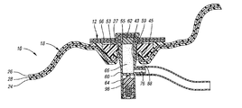
- FIG. 1 illustrates a fuel tank 10 having a venting system or assembly 12 for reduced fuel permeation from the tank 10 .
- tank 10 includes venting assembly 12 for venting a gaseous fluid from the tank 10 containing liquid and gaseous fluids 14 , 16 .
- Liquid and gaseous fluids 14 , 16 may be any fluid used in vehicle fuel tanks as known in the art, e.g., gasoline.
- fuel tank 10 includes tank shell 18 having inner and outer layers 24 , 26 and an ethylene vinyl alcohol (EVOH) layer 28 which is co-extruded between inner and outer layers 24 , 26 preferably but not necessarily by a blow molding process.
- Inner and outer layers 24 , 26 may be made of high density polyethylene.
- Tank shell 18 further includes hole 30 formed therethrough and is configured so that fuel delivery module cover 36 may be removably inserted into hole 30 to attach to tank shell 18 .
- fuel tank 10 is preferably but not necessarily a fuel tank for a vehicle.
- the fuel tank mentioned in this embodiment of the present invention may include any size vehicle tanks, storage tanks, or any other suitable tank without falling beyond the scope or spirit of the present invention.
- FIGS. 2 , 6 a , and 6 b depict tank shell 18 further including an outer lip 27 extending outwardly from the tank shell 18 .
- the inner and outer layers 24 , 26 cooperate to form the outer lip 27 .
- the outer lip 27 defines an aperture 42 formed through the tank shell 18 and has inner and outer sides 43 , 45 extending outwardly from the tank shell 18 .
- FIGS. 2-4 and 6 a - 6 b depict a retention member 53 formed on the outer layer 26 of the tank shell 18 and cooperates with the outer lip 27 .
- the retention member 53 has a bore 55 formed therethrough which is in alignment with the aperture 42 of the tank shell 18 .
- the retention member 53 is made of material having a lower rate of hydrocarbon absorption than the material (e.g. HDPE) comprising the tank shell 18 .
- the retention member 53 may be made of any suitable metal or metal alloy such as aluminum or aluminum alloy.
- the retention member 53 receives the outer lip 27 and is attached to the outer layer 26 about the outer side 45 and partially engaged with the inner side 43 of the outer lip 27 .
- This may be accomplished by any suitable means, such as injection molding the tank shell with the retention member.
- the retention member 53 serves as an expansion boundary against the outer lip 27 , preventing the outer lip 27 from expanding outwardly thereby increasing the aperture size when hydrocarbon swelling occurs during normal use of the tank.
- the outer lip 27 is configured to expand inwardly during hydrocarbon absorption of the tank, since the retention member 53 provides the outer lip 27 with only an inward radial direction of expansion when hydrocarbon absorption occurs.
- the tank shell 18 is configured to be integrated with or formed within the retention member 53 so that disengagement of the retention member 53 from the tank shell 18 is avoided.
- the retention member 53 is structurally configured to allow tank shell 18 to be injection molded within the retention member 53 , thereby securing the retention member 53 with the tank shell 18 .
- the retention member 53 may take on any suitable structural configuration to allow the tank shell 18 to be formed within the retention member 53 , thereby maintaining attachment of the retention member to the tank shell.
- venting valve 48 is disposed through the bore 55 of the retention member 53 and rests thereon such that the venting valve 48 is suspended within the retention member 53 in the fuel tank.
- bore 55 is defined by a circular portion 44 .
- bore 55 is formed in a shape of a typical key hole.
- bore 55 may be formed of any other suitable shape.
- the venting valve 48 is disposed through the bore 55 and is received by the retention member 53 to define a circumferential space 81 between the inner side 43 of the outer lip 27 and the venting valve 48 .
- the retention member 53 is situated about the outer side 45 of the outer lip 27 defining an expansion boundary 57 so that the outer lip 27 only expands toward the venting valve 48 to seal the circumferential space when the tank absorbs hydrocarbons.
- Venting valve 48 includes valve body or housing 60 having top portion 62 and neck portion 64 extending from top portion 62 .
- neck portion 64 includes a radial wall integrally extending from top portion 62 to define an inner space 66 in neck portion 64 in which spring and float assembly 98 is housed as discussed below.
- port 76 extend from neck portion 64 , wherein port 76 is disposed below top portion 62 .
- Neck portion 64 engages retention member 53 in circle portion 44 .
- neck portion 64 is configured to have dimensions or a shape complementing but slightly greater than circle portion 44 . This allows neck portion 64 to be frictionally retained in circle portion 44 .
- top portion 62 is shaped to complement the top surface of the retention member 53 to prevent radial movement of the valve 48 when suspended in bore 55 .
- the complementing shapes of the top portion and the top surface of the retention member may take on any other suitable configuration to prevent the valve 48 from radial movement when suspended in the bore.
- the venting assembly may not be drawn to scale in the figures relative to the tank shell and the aperture. Thus, for example, the neck portion of the venting valve may be inserted through the aperture at an angle.
- Venting system 12 includes internal hose or channel 82 having first and second ends 88 , 90 , wherein first end 88 attaches to port 76 and second end 90 attaches to coupling 92 of fuel delivery module cover 36 so that port 76 is in fluid communication with coupling 92 .
- the gaseous fluid is vented to flow to a separate system, e.g., a vapor canister (not shown), within the vehicle for further processing.
- a separate system e.g., a vapor canister (not shown)
- This allows channel 82 to be in fluid communication with venting valve 48 so that the gaseous fluid may be vented from tank 10 to the vapor canister separate from the tank.
- valve body 60 includes a typical spring and float assembly 98 housed within inner space 66 .
- Spring and float assembly 98 allows venting valve 48 to vent gaseous fluids at a predetermined pressure, e.g., about 1.0 to 3.0 pounds per square inch gauge or about 30 to 60 inches water, without venting liquid fluid therefrom.
- valve body 60 of venting valve 48 includes a spring and float assembly housed therein as a mechanism for allowing gaseous fluids to be vented.
- the valve body may include a grade venting, rollover, fill limit/vent, or shutoff mechanism.
- the venting valve 48 further includes a sealing gasket 59 disposed about valve notch 61 formed about venting valve 48 . As shown in FIG. 2 , the sealing gasket 59 engages the inner side 43 of the outer lip 27 to further define the circumferential space between the outer lip 27 and venting valve 48 .
- this merely is a preferred embodiment and thus, other suitable means may be used without falling beyond the scope or spirit of the present invention.
- sealing cover 96 is mounted onto outer layer 26 of tank shell 18 .
- Sealing cover 96 preferably but not necessarily has corresponding inner and outer layers made of the same material as inner and outer layers 24 , 26 of tank shell 18 and has an EVOH layer disposed there between by blow molding.
- sealing cover 96 and tank shell 18 have substantially the same coefficients of thermal expansion.
- Sealing cover 96 may be attached to outer layer 26 by any suitable means.
- cover 96 is welded onto outer layer 26 by a permeation barrier material to seal top portion 62 of valve 48 between outer layer 26 and cover 96 .
- the valve of this embodiment of the present invention is separate from the sealing cover which is welded onto the outer layer.
- the valve is not required to be in continuous surface contact with the cover, although the cover may merely engage the top portion of the valve.
- the retention member is molded with the outer layer of the tank shell such that the retention member maintains its attachment with the outer layer of the tank shell. Moreover, the retention member is disposed about the venting valve and outer lip of the tank shell such that a boundary is created against the outer lip defining an expansion boundary. As a result, the aperture will only expand inwardly thereby closing the circumferential space between the inner side of the outer lip and the venting valve, when the tank shell absorbs hydrocarbon and “swells.” This provides an enhanced and improved seal, reducing fuel permeation therethrough.
- the sealing cover is welded directly onto the tank shell or with a permeation barrier material, the coefficients of thermal expansions are the same, since the sealing cover and the tank shell are of the same material. It has been found that the sealing cover being made of the same materials as the tank shell significantly reduces the sheer stresses in the permeation barrier materials. In turn, it has been determined that this reduces the risk of delamination of the welded materials.
Landscapes
- Engineering & Computer Science (AREA)
- Mechanical Engineering (AREA)
- Life Sciences & Earth Sciences (AREA)
- Sustainable Development (AREA)
- Sustainable Energy (AREA)
- Chemical & Material Sciences (AREA)
- Combustion & Propulsion (AREA)
- Transportation (AREA)
- Physics & Mathematics (AREA)
- Thermal Sciences (AREA)
- Cooling, Air Intake And Gas Exhaust, And Fuel Tank Arrangements In Propulsion Units (AREA)
Abstract
Description
Claims (24)
Priority Applications (4)
| Application Number | Priority Date | Filing Date | Title |
|---|---|---|---|
| US10/640,600 US6840264B1 (en) | 2003-08-13 | 2003-08-13 | Fuel tank venting system for reduced fuel permeation |
| DE200410039544 DE102004039544A1 (en) | 2003-08-13 | 2004-08-13 | Fuel venting system for low fuel permeation |
| GB0418063A GB2408044B (en) | 2003-08-13 | 2004-08-13 | Fuel tank venting system for reduced fuel permeation |
| FR0408878A FR2858785A1 (en) | 2003-08-13 | 2004-08-13 | FUEL TANK WITH VALVE ASSEMBLY FOR REDUCING FUEL PERMEATION |
Applications Claiming Priority (1)
| Application Number | Priority Date | Filing Date | Title |
|---|---|---|---|
| US10/640,600 US6840264B1 (en) | 2003-08-13 | 2003-08-13 | Fuel tank venting system for reduced fuel permeation |
Publications (1)
| Publication Number | Publication Date |
|---|---|
| US6840264B1 true US6840264B1 (en) | 2005-01-11 |
Family
ID=33030198
Family Applications (1)
| Application Number | Title | Priority Date | Filing Date |
|---|---|---|---|
| US10/640,600 Expired - Lifetime US6840264B1 (en) | 2003-08-13 | 2003-08-13 | Fuel tank venting system for reduced fuel permeation |
Country Status (4)
| Country | Link |
|---|---|
| US (1) | US6840264B1 (en) |
| DE (1) | DE102004039544A1 (en) |
| FR (1) | FR2858785A1 (en) |
| GB (1) | GB2408044B (en) |
Cited By (9)
| Publication number | Priority date | Publication date | Assignee | Title |
|---|---|---|---|---|
| US20040051305A1 (en) * | 2002-09-03 | 2004-03-18 | Rasmussen Gmbh | Part for connecting a fluid line to an opening of a container comprising plastic material or for closing the opening |
| US20110084073A1 (en) * | 2009-10-09 | 2011-04-14 | Sean Whelan | Apparatus and methods for mounting fuel delivery system components to fuel tanks |
| WO2012013287A3 (en) * | 2010-07-30 | 2012-05-31 | Kautex Textron Gmbh & Co. Kg | Thermoplastic tank |
| WO2014194124A1 (en) * | 2013-05-29 | 2014-12-04 | Mcalister Technologies, Llc | Methods for fuel tank recycling and net hydrogen fuel and carbon goods production along with associated apparatus and systems |
| US9314719B2 (en) | 2011-08-12 | 2016-04-19 | Mcalister Technologies, Llc | Filter having spiral-shaped distributor channels |
| US20160201819A1 (en) * | 2013-08-09 | 2016-07-14 | Kautex Textron Gmbh & Co. Kg | Universal shutoff valve |
| US9409126B2 (en) | 2009-02-17 | 2016-08-09 | Mcalister Technologies, Llc | Apparatuses and methods for storing and/or filtering a substance |
| US9534296B2 (en) | 2013-03-15 | 2017-01-03 | Mcalister Technologies, Llc | Methods of manufacture of engineered materials and devices |
| CN107921863A (en) * | 2015-07-31 | 2018-04-17 | 全耐塑料高级创新研究公司 | Liquid vehicle tank comprising a fastened component |
Families Citing this family (1)
| Publication number | Priority date | Publication date | Assignee | Title |
|---|---|---|---|---|
| FR2900092A1 (en) * | 2006-04-21 | 2007-10-26 | Inergy Automotive Systems Res | PROCESS FOR MANUFACTURING A FUEL TANK |
Citations (7)
| Publication number | Priority date | Publication date | Assignee | Title |
|---|---|---|---|---|
| US6189567B1 (en) | 1997-11-25 | 2001-02-20 | Stant Manufacturing Inc. | Tank valve mounting assembly |
| US20020011490A1 (en) | 2000-07-21 | 2002-01-31 | Yachiyo Kogyo Kabushiki Kaisha | Plastic fuel tank having an arrangement for welding a component part in a fuel impermeable manner |
| US6408867B2 (en) | 2000-03-30 | 2002-06-25 | Toyoda Gosei Co., Ltd. | Fuel cutoff valve and fuel tank |
| US6422261B1 (en) | 2000-02-03 | 2002-07-23 | Stant Manufacturing Inc. | Weldable mount for fuel system component |
| US20020096522A1 (en) | 2001-01-19 | 2002-07-25 | Sander Palvoelgyi | Fuel tank with lid |
| US20030062083A1 (en) | 2001-09-28 | 2003-04-03 | Hiroshi Nishi | Fuel cutoff valve |
| US6591857B2 (en) * | 2001-11-29 | 2003-07-15 | Visteon Global Technologies, Inc. | Fuel tank venting system |
Family Cites Families (1)
| Publication number | Priority date | Publication date | Assignee | Title |
|---|---|---|---|---|
| US5028244A (en) * | 1990-06-27 | 1991-07-02 | Stant Inc. | Tank venting control valve assembly |
-
2003
- 2003-08-13 US US10/640,600 patent/US6840264B1/en not_active Expired - Lifetime
-
2004
- 2004-08-13 DE DE200410039544 patent/DE102004039544A1/en not_active Withdrawn
- 2004-08-13 GB GB0418063A patent/GB2408044B/en not_active Expired - Fee Related
- 2004-08-13 FR FR0408878A patent/FR2858785A1/en not_active Withdrawn
Patent Citations (7)
| Publication number | Priority date | Publication date | Assignee | Title |
|---|---|---|---|---|
| US6189567B1 (en) | 1997-11-25 | 2001-02-20 | Stant Manufacturing Inc. | Tank valve mounting assembly |
| US6422261B1 (en) | 2000-02-03 | 2002-07-23 | Stant Manufacturing Inc. | Weldable mount for fuel system component |
| US6408867B2 (en) | 2000-03-30 | 2002-06-25 | Toyoda Gosei Co., Ltd. | Fuel cutoff valve and fuel tank |
| US20020011490A1 (en) | 2000-07-21 | 2002-01-31 | Yachiyo Kogyo Kabushiki Kaisha | Plastic fuel tank having an arrangement for welding a component part in a fuel impermeable manner |
| US20020096522A1 (en) | 2001-01-19 | 2002-07-25 | Sander Palvoelgyi | Fuel tank with lid |
| US20030062083A1 (en) | 2001-09-28 | 2003-04-03 | Hiroshi Nishi | Fuel cutoff valve |
| US6591857B2 (en) * | 2001-11-29 | 2003-07-15 | Visteon Global Technologies, Inc. | Fuel tank venting system |
Cited By (27)
| Publication number | Priority date | Publication date | Assignee | Title |
|---|---|---|---|---|
| US20060197341A1 (en) * | 2002-09-02 | 2006-09-07 | Janos Kertesz | Part for connecting a fluid line to an opening of a container comprising plastic material or for closing the opening |
| US20040051305A1 (en) * | 2002-09-03 | 2004-03-18 | Rasmussen Gmbh | Part for connecting a fluid line to an opening of a container comprising plastic material or for closing the opening |
| US7066498B2 (en) * | 2002-09-03 | 2006-06-27 | Rasmussen Gmbh | Part for connecting a fluid line to an opening of a container comprising plastic material or for closing the opening |
| US7631903B2 (en) * | 2002-09-03 | 2009-12-15 | Norma Germany Gmbh | Part for connecting a fluid line to an opening of a container comprising plastic material or for closing the opening |
| US9409126B2 (en) | 2009-02-17 | 2016-08-09 | Mcalister Technologies, Llc | Apparatuses and methods for storing and/or filtering a substance |
| US20110084073A1 (en) * | 2009-10-09 | 2011-04-14 | Sean Whelan | Apparatus and methods for mounting fuel delivery system components to fuel tanks |
| US20110083989A1 (en) * | 2009-10-09 | 2011-04-14 | Sean Whelan | Apparatus and methods for permanently attaching fuel delivery system components to fuel tanks |
| US20110083771A1 (en) * | 2009-10-09 | 2011-04-14 | Sean Whelan | Overflow prevention apparatus for use with fuel tanks |
| US20110084076A1 (en) * | 2009-10-09 | 2011-04-14 | Sean Whelan | Pressure relief apparatus for use with fuel delivery systems |
| US8789719B2 (en) * | 2009-10-09 | 2014-07-29 | Brunswick Corporation | Apparatus and methods for permanently attaching fuel delivery system components to fuel tanks |
| US8833346B2 (en) | 2009-10-09 | 2014-09-16 | Brunswick Corporation | Apparatus and methods for mounting fuel delivery system components to fuel tanks |
| US20110083772A1 (en) * | 2009-10-09 | 2011-04-14 | Sean Whelan | Apparatus and methods to couple fuel delivery system components to fuel tanks |
| US10086691B2 (en) | 2009-10-09 | 2018-10-02 | Brunswick Corporation | Pressure relief apparatus for use with fuel delivery systems |
| US9222450B2 (en) | 2009-10-09 | 2015-12-29 | Brunswick Corporation | Pressure relief apparatus for use with fuel delivery systems |
| WO2012013287A3 (en) * | 2010-07-30 | 2012-05-31 | Kautex Textron Gmbh & Co. Kg | Thermoplastic tank |
| US9132728B2 (en) | 2010-07-30 | 2015-09-15 | Kautex Textron Gmbh & Co. Kg | Thermoplastic tank |
| US9314719B2 (en) | 2011-08-12 | 2016-04-19 | Mcalister Technologies, Llc | Filter having spiral-shaped distributor channels |
| US9534296B2 (en) | 2013-03-15 | 2017-01-03 | Mcalister Technologies, Llc | Methods of manufacture of engineered materials and devices |
| WO2014194124A1 (en) * | 2013-05-29 | 2014-12-04 | Mcalister Technologies, Llc | Methods for fuel tank recycling and net hydrogen fuel and carbon goods production along with associated apparatus and systems |
| US9511663B2 (en) | 2013-05-29 | 2016-12-06 | Mcalister Technologies, Llc | Methods for fuel tank recycling and net hydrogen fuel and carbon goods production along with associated apparatus and systems |
| US9079489B2 (en) * | 2013-05-29 | 2015-07-14 | Mcalister Technologies, Llc | Methods for fuel tank recycling and net hydrogen fuel and carbon goods production along with associated apparatus and systems |
| US20140352801A1 (en) * | 2013-05-29 | 2014-12-04 | Mcalister Technologies, Llc | Methods for fuel tank recycling and net hydrogen fuel and carbon goods production along with associated apparatus and systems |
| US20160201819A1 (en) * | 2013-08-09 | 2016-07-14 | Kautex Textron Gmbh & Co. Kg | Universal shutoff valve |
| US10753250B2 (en) * | 2013-08-09 | 2020-08-25 | Kautex Textron Gmbh & Co. Kg | Universal shutoff valve |
| CN107921863A (en) * | 2015-07-31 | 2018-04-17 | 全耐塑料高级创新研究公司 | Liquid vehicle tank comprising a fastened component |
| US11021051B2 (en) | 2015-07-31 | 2021-06-01 | Plastic Omnium Advanced Innovation And Research | Liquid vehicle tank comprising a fastened component |
| CN107921863B (en) * | 2015-07-31 | 2021-08-27 | 全耐塑料高级创新研究公司 | Liquid vehicle tank comprising a fastened component |
Also Published As
| Publication number | Publication date |
|---|---|
| GB0418063D0 (en) | 2004-09-15 |
| FR2858785A1 (en) | 2005-02-18 |
| GB2408044B (en) | 2005-09-21 |
| DE102004039544A1 (en) | 2005-06-09 |
| GB2408044A (en) | 2005-05-18 |
Similar Documents
| Publication | Publication Date | Title |
|---|---|---|
| US6591857B2 (en) | Fuel tank venting system | |
| US8789719B2 (en) | Apparatus and methods for permanently attaching fuel delivery system components to fuel tanks | |
| US7455326B2 (en) | Connection tube for fuel tank | |
| US6289915B1 (en) | Permeation and leak preventative design for fuel tank attachments | |
| EP1705051B1 (en) | Low profile overfill limit device with reverse flow capability | |
| EP1332906B1 (en) | Method and system for controlling liquid fuel and vapor flow during refueling of a motor vehicle fuel tank | |
| US7543597B2 (en) | Vent valve assembly with lever arrangement | |
| US6840264B1 (en) | Fuel tank venting system for reduced fuel permeation | |
| US6257287B1 (en) | Fuel fill pipe shut-off device | |
| US8899265B2 (en) | Plastic fuel tank with increased deformation stability | |
| US4963169A (en) | Fuel tank venting separator | |
| EP1211196A1 (en) | Low permeation fittings, low permeation containers utilizing same, and methods for forming same | |
| US9409476B2 (en) | Fuel fill apparatus for use with fuel delivery systems | |
| CA2287727A1 (en) | Two-stage fuel tank vapor recovery vent valve and method of making same | |
| JP2005335691A (en) | Vapor recovery device in refueling | |
| JP2005506239A (en) | Fuel tank and manufacturing method thereof | |
| US20070144612A1 (en) | Spill avoidance system and venting system for a storage tank using pressure transfer methods | |
| JP2005532187A (en) | Tank opening sealing system and sealing method | |
| US8997782B2 (en) | Inlet control valves for use with fuel delivery systems | |
| US7082964B1 (en) | Attachment structure of a component in a fuel tank made of resin | |
| JP2003025857A (en) | Structure for mounting cylindrical body to fuel tank | |
| US20040020533A1 (en) | Low permeation weldable fuel tank valve | |
| JP2002276882A (en) | Structure for mounting cylindrical body on fuel tank | |
| JP4160885B2 (en) | Backflow prevention valve mounting structure for plastic fuel tank | |
| WO2020164806A1 (en) | Multi-material orifice plates for vent valve assemblies of liquid containment systems |
Legal Events
| Date | Code | Title | Description |
|---|---|---|---|
| AS | Assignment |
Owner name: VISTEON GLOBAL TECHNOLOGIES, INC., MICHIGAN Free format text: ASSIGNMENT OF ASSIGNORS INTEREST;ASSIGNORS:BHAVSAR, DAVEN C.;GINNARD, ROBERT J.;KNAGGS, RICHARD A.;REEL/FRAME:014399/0777 Effective date: 20030812 |
|
| STCF | Information on status: patent grant |
Free format text: PATENTED CASE |
|
| AS | Assignment |
Owner name: AUTOMOTIVE COMPONENTS HOLDINGS, LLC, MICHIGAN Free format text: ASSIGNMENT OF ASSIGNORS INTEREST;ASSIGNOR:VISTEON GLOBAL TECHNOLOGIES, INC.;REEL/FRAME:016835/0448 Effective date: 20051129 |
|
| FPAY | Fee payment |
Year of fee payment: 4 |
|
| FPAY | Fee payment |
Year of fee payment: 8 |
|
| AS | Assignment |
Owner name: INERGY AUTOMOTIVE SYSTEMS RESEARCH (SA), BELGIUM Free format text: ASSIGNMENT OF ASSIGNORS INTEREST;ASSIGNOR:AUTOMOTIVE COMPONENTS HOLDINGS, LLC;REEL/FRAME:031330/0498 Effective date: 20110805 |
|
| FPAY | Fee payment |
Year of fee payment: 12 |
|
| AS | Assignment |
Owner name: PLASTIC OMNIUM ADVANCED INNOVATION AND RESEARCH, BELGIUM Free format text: CHANGE OF NAME;ASSIGNOR:INERGY AUTOMOTIVE SYSTEMS RESEARCH;REEL/FRAME:046550/0889 Effective date: 20150623 Owner name: PLASTIC OMNIUM ADVANCED INNOVATION AND RESEARCH, B Free format text: CHANGE OF NAME;ASSIGNOR:INERGY AUTOMOTIVE SYSTEMS RESEARCH;REEL/FRAME:046550/0889 Effective date: 20150623 |