EP1394413A1 - Hubkolbenverdichter für gasförmige Medien mit verringerter Bauhöhe - Google Patents
Hubkolbenverdichter für gasförmige Medien mit verringerter Bauhöhe Download PDFInfo
- Publication number
- EP1394413A1 EP1394413A1 EP02019521A EP02019521A EP1394413A1 EP 1394413 A1 EP1394413 A1 EP 1394413A1 EP 02019521 A EP02019521 A EP 02019521A EP 02019521 A EP02019521 A EP 02019521A EP 1394413 A1 EP1394413 A1 EP 1394413A1
- Authority
- EP
- European Patent Office
- Prior art keywords
- longitudinal axis
- piston
- cylinder
- axis
- reciprocating compressor
- Prior art date
- Legal status (The legal status is an assumption and is not a legal conclusion. Google has not performed a legal analysis and makes no representation as to the accuracy of the status listed.)
- Granted
Links
- 239000000463 material Substances 0.000 claims description 2
- 230000006835 compression Effects 0.000 description 22
- 238000007906 compression Methods 0.000 description 22
- 230000008901 benefit Effects 0.000 description 14
- 240000006829 Ficus sundaica Species 0.000 description 9
- 230000009467 reduction Effects 0.000 description 3
- 238000006073 displacement reaction Methods 0.000 description 2
- 238000005516 engineering process Methods 0.000 description 2
- 238000011144 upstream manufacturing Methods 0.000 description 2
- 230000008859 change Effects 0.000 description 1
- 238000005056 compaction Methods 0.000 description 1
- 238000010276 construction Methods 0.000 description 1
- 229920001971 elastomer Polymers 0.000 description 1
- 239000000806 elastomer Substances 0.000 description 1
- 230000006872 improvement Effects 0.000 description 1
- 238000004519 manufacturing process Methods 0.000 description 1
- 238000000034 method Methods 0.000 description 1
- 230000008569 process Effects 0.000 description 1
- 238000007789 sealing Methods 0.000 description 1
- 230000001360 synchronised effect Effects 0.000 description 1
Images




Classifications
-
- F—MECHANICAL ENGINEERING; LIGHTING; HEATING; WEAPONS; BLASTING
- F04—POSITIVE - DISPLACEMENT MACHINES FOR LIQUIDS; PUMPS FOR LIQUIDS OR ELASTIC FLUIDS
- F04B—POSITIVE-DISPLACEMENT MACHINES FOR LIQUIDS; PUMPS
- F04B39/00—Component parts, details, or accessories, of pumps or pumping systems specially adapted for elastic fluids, not otherwise provided for in, or of interest apart from, groups F04B25/00 - F04B37/00
- F04B39/12—Casings; Cylinders; Cylinder heads; Fluid connections
-
- F—MECHANICAL ENGINEERING; LIGHTING; HEATING; WEAPONS; BLASTING
- F04—POSITIVE - DISPLACEMENT MACHINES FOR LIQUIDS; PUMPS FOR LIQUIDS OR ELASTIC FLUIDS
- F04B—POSITIVE-DISPLACEMENT MACHINES FOR LIQUIDS; PUMPS
- F04B39/00—Component parts, details, or accessories, of pumps or pumping systems specially adapted for elastic fluids, not otherwise provided for in, or of interest apart from, groups F04B25/00 - F04B37/00
- F04B39/0005—Component parts, details, or accessories, of pumps or pumping systems specially adapted for elastic fluids, not otherwise provided for in, or of interest apart from, groups F04B25/00 - F04B37/00 adaptations of pistons
- F04B39/0022—Component parts, details, or accessories, of pumps or pumping systems specially adapted for elastic fluids, not otherwise provided for in, or of interest apart from, groups F04B25/00 - F04B37/00 adaptations of pistons piston rods
-
- F—MECHANICAL ENGINEERING; LIGHTING; HEATING; WEAPONS; BLASTING
- F04—POSITIVE - DISPLACEMENT MACHINES FOR LIQUIDS; PUMPS FOR LIQUIDS OR ELASTIC FLUIDS
- F04B—POSITIVE-DISPLACEMENT MACHINES FOR LIQUIDS; PUMPS
- F04B39/00—Component parts, details, or accessories, of pumps or pumping systems specially adapted for elastic fluids, not otherwise provided for in, or of interest apart from, groups F04B25/00 - F04B37/00
- F04B39/0094—Component parts, details, or accessories, of pumps or pumping systems specially adapted for elastic fluids, not otherwise provided for in, or of interest apart from, groups F04B25/00 - F04B37/00 crankshaft
Definitions
- the present invention relates to a reciprocating compressor for gaseous media, in particular for a level control system in motor vehicles according to the preamble of Claim 1.
- Such a reciprocating compressor is known from the German patent DE19903025C2 known.
- the reciprocating compressor described in this document for gaseous Media has a movable within a cylinder piston.
- An outside of the Cylinder lying end of the piston is about a crankshaft with a drive shaft connected to an electric motor.
- the reciprocating compressor and the drive device are each disposed in a compressor housing and a drive device housing.
- On the compressor housing in the region of the piston is a tubular, integral with the Compressor housing formed extension piece, wherein the compressor housing and the drive device housing are integrally formed.
- the one from this Publication known and designed in a conventional design reciprocating compressor has the disadvantage of a large design and high friction of the piston ring on the Cylinder run, especially in the intake stroke.
- a reciprocating compressor which drives a piston engine via a drive motor.
- One Working space of a cylinder has a volume which is between a minimum value and a maximum value pulses. Separated, with inlet and outlet and outlet ports, a medium is introduced through the inlet and through the outlet cast out.
- the working space of the cylinder is one of a crankcase enclosed crankshaft space upstream.
- the crankshaft space is connected to the environment, wherein the air inlet valve is a rotary valve and synchronous to the rotational movement of Crankshaft is controllable.
- the rotary valve is integrated into the intake manifold Upstream suction filter.
- the intake manifold, the intake filter and the rotary valve form a single unit.
- Also known from this document and in Conventional design designed reciprocating compressor has the disadvantage of a large Construction and high friction of the piston ring on the cylinder bore especially in the intake stroke.
- the object of the invention is a reciprocating compressor with a low profile and a To provide reduced friction of the piston ring on the cylinder bore.
- the pivot angle of the piston ring relative to the cylinder bore and thus the Piston ring longitudinal axis with respect to the longitudinal axis of the cylinder bore is with respect Deformation, pressure load and thus tightness of the piston ring to a maximum limited permissible value. This is especially true in the upward movement of the piston (the compression stroke), because then increased demands for deformation, Pressure load and thus tightness at the contact point piston ring and Cylinder run are made.
- the advantage of the invention is in particular to see that as a result, the height of the reciprocating compressor by reducing reduces the connecting rod length and correspondingly reduced length of the cylinder bore can be, without the piston ring unduly high stress and the maximum permissible swivel angle in the compression stroke to exceed.
- the reduced height the reciprocating compressor can be reduced by a reduction of the connecting rod length and achieve corresponding reduced length of the cylinder bore, wherein the longitudinal axis of the Cylinder track is arranged offset from the first axis of space, so that the maximum swivel angle of the piston ring with respect to the cylinder bore in Compression stroke does not exceed the maximum permissible value.
- Another advantage The invention can be seen in particular in that the maximum pivot angle in Suction stroke where there is no increased requirement for the piston ring with regard to deformation, Pressure load and tightness are made greater than the maximum allowable Swivel angle is what leads to a reduction of friction and an improvement of the Intake process in the intake stroke leads.
- the Longitudinal axis of the cylinder bore relative to the first axis of space is offset in parallel.
- the longitudinal axis of the cylinder bore perpendicular to the longitudinal axis of the motor drive shaft which is production technology easy can be produced.
- the cylindrical Component is rotationally symmetric and thus - especially from standard components - simple to be finished.
- the Longitudinal axis of the cylinder bore does not intersect the pivot point of the drive shaft.
- One Advantage of the development of the invention is that thereby the pivot angle of the Piston ring against the cylinder bore, especially in the compression stroke within a wide range can be adjusted.
- the angle between the longitudinal axis of the Cylinder bore and the first axis of space may comprise a very wide range, by choosing a very low or a very high value.
- the Longitudinal axis of the cylinder bore is pivoted relative to the first spatial axis.
- One Advantage of the development of the invention is that thereby the pivot angle of the Piston ring against the cylinder bore especially in the compression stroke on best can be adjusted and the maximum reduction in the height of the Reciprocating compressor is achieved.
- Another advantage of the invention is that the pivot angle of the piston ring relative to the cylinder bore in particular in the compression stroke over the largest possible distance of the compression and / or Suction stroke within a for the tightness of the piston ring to Cylinder runway, the piston ring wear and / or the Kolbenringlebensdauer optimal range moves.
- the Longitudinal axis of the cylinder bore relative to the first axis of space by an angle is pivoted between 0.5 ° and 7 °.
- the Intersection of the longitudinal axis of the cylinder bore with the first axis of space in the area the up and down movement of the piston is within the cylinder bore.
- the Intersection of the longitudinal axis of the cylinder track with the first axis of space in the middle the range of up and down movement of the piston within the cylinder bore lies.
- the Intersection of the longitudinal axis of the cylinder track with the first axis in the upper space Inversion point of the piston is within the cylinder bore.
- the Surface of the end piece of the cylinder head which is oriented towards the crankcase, has a spherical or barrel-shaped contour and the outer surface of the curvature of the spherical or barrel-shaped contour is oriented towards the crankcase, so that the Dead space is reduced and thus the efficiency and efficiency of the Reciprocating compressor is increased.
- FIG. 1 describes a reciprocating compressor 10 of conventional design.
- Cylinder head 20 is in this embodiment in one piece with a cylindrical Component 56 is formed and has an outlet channel 22.
- the outlet channel 22 becomes the Drier housing 28 closed by an outlet valve 24, which consists of a Elastomer body, a leaf valve or the like.
- One in the cylinder head 20 attached valve spring 26 presses the outlet valve 24 at no or little Pressure gradient on the sealing seat of the outlet channel 22 and closes this for Dryer housing 28 out.
- the function of a dryer is especially for air well known and will not be described in detail here.
- the cylindrical component 56 has a cylinder bore 58 with a high Surface finish on and is connected at one end to a crankcase 42.
- the cylinder head 20 and the cylindrical member 56 may also be separate Components are manufactured.
- the cylindrical component 56 may be made a standard component, such as a pipe, are produced inexpensively. By means of a Press connection or the like, the cylinder head 20 with the cylindrical Component 56 connected.
- crankshaft 38 In the crankcase 42, a crankshaft 38 is arranged, which with a pin in the Inner ring of a bearing 36 is pressed. The outer ring of the bearing 36 is in the Crank hammers attached.
- the crankshaft 38 has a crankshaft journal 44, which serves to receive a bearing 40 and thus a connecting rod 50.
- the bearing 40 is firmly connected to the connecting rod 50 and is by means of a screw 46 and a disc 48th or the like fixed to the crankshaft journal 44.
- the connecting rod 50 has a Longitudinal axis 64, which in this embodiment with the longitudinal axis of a fixed connected to the connecting rod 50 piston 60 and the longitudinal axis of a piston 60th fixed piston ring 54 matches.
- the piston 60 is together with the connecting rod 50 as a so-called oscillating piston executed, i. the piston 60 is rigidly connected to the connecting rod 50.
- an inlet channel 62 is arranged, which communicates with the compression space Room connects to the crankcase 42 out.
- the inlet channel 62 is at the Upward movement of the piston 60 (compression stroke) from an inlet valve 66 to closed, so that no air from the compression space to the interior of the Crankcase 42 can flow, and is in the downward movement of the piston 60th (Ansaughub) open so that air from the interior of the crankcase 42 for Compaction space can flow.
- the inlet channel 62 and so that the inlet valve 66 are arranged in the cylinder head 20.
- the inlet valve 66 as shown in this embodiment, as a leaf valve or in known Be designed as an elastomeric valve body with or without valve spring.
- the symmetry axis of the bearing 36 coincides with a drive shaft 31 a fixed to the Crankshaft 38 connected drive shaft 34 of the drive unit match.
- the Drive unit is formed in this embodiment of an electric motor whose function is known and will not be described in detail. It is the use of everyone other known drive technology, such as a pneumatic or hydraulic drive, possible.
- the drive shaft 34 of the electric motor is on the stored one side in the bearing 36 and on the other side in a bearing 32.
- the Bearing 32 is fixed in a motor housing 30 which fixed to the crankcase 42nd connected is.
- FIG. 2 shows schematically the kinematics of a reciprocating compressor.
- a schematic illustrated piston 228 and a schematically illustrated connecting rod 230 are in the upper Dead center of the piston 228 shown. In this position, there is also a fulcrum of the crankshaft journal 44 (s.Fig.1) in the upper reversal point 231.
- a first spatial axis 222 intersects the upper reversal point 231 of the crankshaft journal 44 (s.Fig.1) and a pivot point 232 of the drive shaft 31 (s.Fig.1).
- a longitudinal axis 220 of the cylindrical member 56 and the cylinder barrel 58 intersects the pivot 232 the drive axis 31 (s.Fig.1) not, but is compared to the first spatial axis 222 to an angle 238 pivoted.
- the pivot angle 238 is in one Range between 0.5 ° and 7 °.
- the pivot point of the crankshaft journal 44 (s.Fig.1) describes at a turn around 360 ° about the pivot point 232 of the drive axle 31 (s.Fig.1) a movement circle 234, which has a radius which corresponds to the eccentricity of the crankshaft 38 (see FIG. equivalent.
- the direction of movement 239 of the pivot point of the crankshaft journal 44 (s.Fig.1) runs counterclockwise.
- Between the top of the piston 228 and the surface of the cylinder head 224 is the smallest possible gap, which is the Represents dead volume of the reciprocating compressor.
- the area of the cylinder head 224 is perpendicular to the first spatial axis 222.
- a misalignment of this is the first Room axis 222 possible, for example, the surface of the cylinder head 224 perpendicular extend to the longitudinal axis of the cylinder bore, so that the dead volume as low as possible is held.
- the figure 2a also shows schematically the kinematics of a reciprocating compressor.
- Piston 228 is shown in its bottom dead center.
- the crankshaft journal 44 (s.Fig.1) is in its lower reversal point 235.
- the intersection 221 of Longitudinal axis 220 of the cylinder bore 58 with the first spatial axis 222 is within the Cylinder run and within a range of movement 226 of the piston 228th
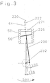
- FIG. 3 shows the piston 228 and the connecting rod 230 in the maximum pivoting position in the compression stroke.
- the crankshaft connection of the fulcrum of the Drive axis 232 to the pivot point of the crankshaft journal
- the longitudinal axis 64 of the piston ring not shown, which in this Embodiment identical to the longitudinal axis of the piston 228 and the connecting rod 230th is, relative to the longitudinal axis 220 of the cylinder bore 58 has a pivot angle 236 on.
- the swivel angle 236 corresponds to the maximum swivel angle of Piston ring to the cylinder bore 58 in the compression stroke.
- FIG. 4 shows the piston 228 and the connecting rod 230 in the maximum pivoting position in the intake stroke.
- the crankshaft connection of the fulcrum of the Drive axis 232 to the pivot point of the crankshaft journal
- the longitudinal axis 64 of the piston ring not shown, which in this Embodiment identical to the longitudinal axis 64 of the piston 228 and the connecting rod 230th is, relative to the longitudinal axis 220 of the cylinder bore 58 has a pivot angle 240 on.
- the swivel angle 240 corresponds to the maximum swivel angle of Piston ring to the cylinder bore 58 in the intake stroke.
- the maximum pivot angle 236 in the compression stroke is smaller than that maximum swivel angle 240 in the intake stroke.
- Figure 5 shows the piston 228 and the connecting rod 230 in a position during the Verdichtungshubes shortly before top dead center.
- the longitudinal axis 64 of the piston ring, of the piston 228 and / or the connecting rod 230 is at the time shown in Fig.5 identical to the longitudinal axis 220 of the cylinder barrel 58.
- the piston 228 facing surface of the cylinder head 224 round or cylindrically shaped.
- the outer contour of the rounding of the surface 224 points respectively in the direction of the piston, so that the dead volume is as low as possible.
- the middle-point the rounding or the longitudinal axis of the cylinder of the surface 224 lies on or intersects Preferably, the longitudinal axis 220 of the cylinder bore 58. It is also conceivable that the first spatial axis 222 or another axis the center of the rounding or the Longitudinal axis of the cylinder of the surface 224 intersects.
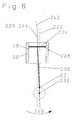
- FIG. 6 shows schematically the kinematics of an embodiment of a Reciprocating compressor according to claim 2.
- the longitudinal axis 220 of the cylinder bore 58 is offset parallel to the first space axis 222 and does not intersect the fulcrum 232 of the drive shaft 31 (s.Fig.1).
- the parallel Displacement of the longitudinal axis 220 to the first spatial axis 222 can either so be made that the longitudinal axis 242 of the connecting rod 230 in two points during the suction stroke (as shown) or in two points during the compression stroke with the longitudinal axis 220 of the cylinder barrel 58 match.
- the longitudinal axis 242 of the connecting rod 230 and the longitudinal axis 244 of the piston 228 and / or the piston ring is not identical.
- the axis 244 of the piston 228 and / or the piston ring have a different pivot angle relative to the longitudinal axis 220 of the Cylinder runway 58, as the longitudinal axis 242 of the connecting rod 230.
- this Embodiment agrees the longitudinal axis 220 of the cylinder bore 58 in the upper Dead center with the longitudinal axis 244 of the piston or the piston ring match, so that a very low dead volume arises.
Landscapes
- Engineering & Computer Science (AREA)
- Mechanical Engineering (AREA)
- General Engineering & Computer Science (AREA)
- Compressor (AREA)
- Compressors, Vaccum Pumps And Other Relevant Systems (AREA)
Abstract
Description
- Fig. 1
- Eine Schnittansicht eines Hubkolbenverdichters
- Fig.2-6
- Eine schematische Darstellung der Kinematik eines Hubkolbenverdichters
- 10
- Hubkolbenverdichter
- 20
- Zylinderkopf
- 22
- Auslasskanal
- 24
- Auslassventil
- 26
- Ventilfeder
- 28
- Trockner
- 30
- Motorgehäuse
- 31
- Antriebsachse
- 32
- Lager
- 34
- Antriebswelle
- 36
- Lager
- 38
- Kurbelwelle
- 40
- Lager
- 42
- Kurbelgehäuse
- 44
- Kurbelwellenzapfen
- 46
- Schraube
- 48
- Scheibe
- 50
- Pleuel
- 52
- Niet
- 54
- Kolbenring
- 56
- Zylinderförmiges Bauteil
- 58
- Zylinderlaufbahn
- 60
- Kolben
- 62
- Einlasskanal
- 64
- Längsachse (Kolben, Kolbenring, Pleuel)
- 66
- Einlassventil
- 220
- Längsachse der Zylinderlaufbahn
- 221
- Schnittpunkt (Längsachse 220 + erste Raumachse 222)
- 222
- Erste Raumachse
- 224
- Fläche des Zylinderkopfes
- 226
- Arbeitsbereich des Kolbens
- 228
- Kolben (schematisch)
- 230
- Pleuel (schematisch)
- 231
- Oberer Umkehrpunkt Kurbelwellenzapfen
- 232
- Drehpunkt der Antriebsachse
- 234
- Bewegungskreis des Kurbelwellenzapfens (Exzentrizität)
- 235
- Unterer Umkehrpunkt Kurbelwellenzapfen
- 236
- Maximaler Schwenkwinkel im Verdichtungshub
- 238
- Schwenkwinkel Längsachse der Zylinderlaufbahn zur ersten Raumachse
- 240
- Maximaler Schwenkwinkel im Ansaughub
- 242
- Längsachse (Pleuel)
- 244
- Längsachse (Kolben, Kolbenring)
Claims (10)
- Hubkolbenverdichter (10) für gasförmige Medien, insbesondere für eine Niveauregelanlage in Kraftfahrzeugen, enthaltenddadurch gekennzeichnet, dasseine Antriebsquelle und ein Kurbelgehäuse (42), die miteinander verbunden sind, wobei eine Antriebswelle (34) eine daran befestigte Kurbelwelle (38) mit einem Kurbelwellenzapfen (44) antreibt,einen Zylinderkopf (20), welcher an dem Kurbelgehäuse (42) befestigt ist,mindestens eine Auslassöffnung (22) mit mindestens einem Auslassventil (24) und mindestens eine Einlassöffnung (62) mit mindestens einem Einlassventil (66),ein zylinderförmiges Bauteil (56), welches an dem Kurbelgehäuse (42) befestigt ist und eine innenliegende Zylinderlaufbahn (58) mit einer Längsachse (220) aufweist,ein Pleuel (50, 230) mit einem daran angebundenen Kolben (60, 228) mit einem Kolbenring (54), wobei das Pleuel (50, 230) von der Kurbelwelle (38) und damit der Kolben (60, 228) in der Zylinderlaufbahn (58) hin- und herbewegt wird,eine erste Raumachse (222), die den Drehpunkt (232) der Antriebswelle (34)und den Drehpunkt des Kurbelwellenzapfens (44) in einem oberen Umkehrpunkt (231) des Kurbelwellenzapfens (44) schneidet,
der maximale Schwenkwinkel (238, 240) der Kolbenringlängsachse (64, 244) gegenüber der Längsachse (220) der Zylinderlaufbahn (58) bei der Aufwärtsbewegung des Kolbens kleiner ist, als bei der Abwärtsbewegung des Kolbens (60, 228) und dass die Längsachse (220) der Zylinderlaufbahn (58) gegenüber der ersten Raumachse (222) versetzt ist. - Hubkolbenverdichter (10) nach Anspruch 1 dadurch gekennzeichnet, dass
die Längsachse (220) der Zylinderlaufbahn (58) gegenüber der ersten Raumachse (222) parallel versetzt ist. - Hubkolbenverdichter (10) nach Anspruch 1 dadurch gekennzeichnet, dass
die Längsachse (220) der Zylinderlaufbahn (58) den Drehpunkt (232) der Antriebswelle (34) nicht schneidet. - Hubkolbenverdichter (10) nach Anspruch 1 dadurch gekennzeichnet, dass
die Längsachse (220) der Zylinderlaufbahn (58) gegenüber der ersten Raumachse (222) verschwenkt ist. - Hubkolbenverdichter (10) nach Anspruch 4 dadurch gekennzeichnet, dass
die Längsachse (220) der Zylinderlaufbahn (58) gegenüber der ersten Raumachse (222) um einen Winkel zwischen 0,5° und 7° verschwenkt ist. - Hubkolbenverdichter (10) nach einem oder mehreren der vorherigen Ansprüche dadurch gekennzeichnet, dass
der Schnittpunkt der Längsachse (220) der Zylinderlaufbahn mit der ersten Raumachse (222) im Bereich der Auf- und Abwärtsbewegung (226) des Kolbens (60, 228) innerhalb der Zylinderlaufbahn (58) liegt. - Hubkolbenverdichter (10) nach einem oder mehreren der vorherigen Ansprüche dadurch gekennzeichnet, dass
der Schnittpunkt der Längsachse (220) der Zylinderlaufbahn (58) mit der ersten Raumachse (222) in der Mitte des Bereiches der Auf- und Abwärtsbewegung (226) des Kolbens (60, 228) innerhalb der Zylinderlaufbahn (58) liegt. - Hubkolbenverdichter (10) nach einem oder mehreren der vorherigen Ansprüche dadurch gekennzeichnet, dass
der Schnittpunkt der Längsachse (220), der Zylinderlaufbahn (58) mit der ersten Raumachse (222) im oberen Umkehrpunkt des Kolbens (60, 228) innerhalb der Zylinderlaufbahn (58) liegt. - Hubkolbenverdichter (10) nach einem oder mehreren der vorherigen Ansprüche dadurch gekennzeichnet, dass
die Auslassöffnung (22) mit dem die Auslassöffnung (22) umgebenden Material in die Zylinderlaufbahn (58) einseitig eintaucht und die Ebene des Endstückes (224) des Zylinderkopfes (20), welches zum Kurbelgehäuse (42) hin orientiert ist, senkrecht zur ersten Raumachse (222) verläuft. - Hubkolbenverdichter (10) nach einem oder mehreren der vorherigen Ansprüche dadurch gekennzeichnet, dass
die Fläche (224) des Endstückes des Zylinderkopfes (20), welche zum Kurbelgehäuse (42) hin orientiert ist, eine kugel- oder tonnenförmige Kontur aufweist und die Außenfläche der Wölbung der kugel- oder tonnenförmigen Kontur zum Kurbelgehäuse (42) hin orientiert ist.
Priority Applications (4)
| Application Number | Priority Date | Filing Date | Title |
|---|---|---|---|
| EP02019521.0A EP1394413B1 (de) | 2002-08-31 | 2002-08-31 | Hubkolbenverdichter für gasförmige Medien mit verringerter Bauhöhe |
| JP2003179945A JP2004092638A (ja) | 2002-08-31 | 2003-06-24 | 低減された全高を有するガス状媒体のための往復ピストン圧縮機 |
| KR1020030060173A KR100935749B1 (ko) | 2002-08-31 | 2003-08-29 | 기체용 왕복 피스톤 압축기 |
| US10/652,473 US7179064B2 (en) | 2002-08-31 | 2003-09-02 | Reciprocating piston compressor for a gaseous medium |
Applications Claiming Priority (1)
| Application Number | Priority Date | Filing Date | Title |
|---|---|---|---|
| EP02019521.0A EP1394413B1 (de) | 2002-08-31 | 2002-08-31 | Hubkolbenverdichter für gasförmige Medien mit verringerter Bauhöhe |
Publications (2)
| Publication Number | Publication Date |
|---|---|
| EP1394413A1 true EP1394413A1 (de) | 2004-03-03 |
| EP1394413B1 EP1394413B1 (de) | 2016-10-12 |
Family
ID=31197880
Family Applications (1)
| Application Number | Title | Priority Date | Filing Date |
|---|---|---|---|
| EP02019521.0A Expired - Lifetime EP1394413B1 (de) | 2002-08-31 | 2002-08-31 | Hubkolbenverdichter für gasförmige Medien mit verringerter Bauhöhe |
Country Status (4)
| Country | Link |
|---|---|
| US (1) | US7179064B2 (de) |
| EP (1) | EP1394413B1 (de) |
| JP (1) | JP2004092638A (de) |
| KR (1) | KR100935749B1 (de) |
Cited By (7)
| Publication number | Priority date | Publication date | Assignee | Title |
|---|---|---|---|---|
| EP1801416A1 (de) * | 2005-12-22 | 2007-06-27 | WABCO GmbH | Hubkolbenmaschine |
| CN101331318B (zh) * | 2006-11-27 | 2011-05-11 | 成周桓 | 空气压缩机的直用曲轴 |
| DE102010054709A1 (de) | 2010-12-16 | 2012-06-21 | Wabco Gmbh | Lufttrockner-System, Druckluftversorgungsanlage, pneumatisches System und Verfahren zum Betreiben einer Pneumatikanlage |
| DE102012005345A1 (de) | 2011-12-23 | 2013-06-27 | Wabco Gmbh | Druckluftversorgungsanlage, Druckluftversorgungssystem, Fahrzeug und Verwendung der Druckluftversorgungsanlage |
| CN103742392A (zh) * | 2007-11-30 | 2014-04-23 | 株式会社日立制作所 | 汽缸装置、压缩机及汽缸装置的制造方法 |
| DE102012024757A1 (de) | 2012-12-19 | 2014-06-26 | Wabco Gmbh | Ringförmiges Dichtungselement, Ventil, Druckluftversorgungsanlage, Druckluftversorgungssystem und Fahrzeug |
| DE102016013036A1 (de) | 2016-11-02 | 2018-05-03 | Wabco Gmbh | Hubkolbenmaschine, insbesondere ein-, zwei- oder mehrstufiger Kolbenkompressor, Druckluftversorgungsanlage, Druckluftversorgungssystem und Fahrzeug, insbesondere PKW mit einer Druckluftversorungsanlage, Verfahren zur Montage einer Hubkolbenmaschine und Verfahren zum Betrieb einer Hubkolbenmaschine, insbesondere an einer Druckluftversorgungsanlage. |
Families Citing this family (20)
| Publication number | Priority date | Publication date | Assignee | Title |
|---|---|---|---|---|
| JP4752241B2 (ja) * | 2004-11-01 | 2011-08-17 | パナソニック株式会社 | 往復動式圧縮機 |
| DE102005009947A1 (de) * | 2005-03-04 | 2006-09-07 | Wabco Gmbh & Co.Ohg | Hubkolbenmaschine |
| USD566131S1 (en) | 2006-09-01 | 2008-04-08 | Continental Aktiengesellschaft | Device for sealing inflatable objects |
| US8435013B2 (en) | 2007-02-09 | 2013-05-07 | Daikin Industries, Ltd. | Reciprocating compressor and oxygen concentrator |
| JP4872938B2 (ja) * | 2008-02-08 | 2012-02-08 | ダイキン工業株式会社 | 往復動圧縮機及び酸素濃縮装置 |
| US20100158715A1 (en) * | 2008-12-24 | 2010-06-24 | Min-Hsieng Wang | Mute compressor |
| US20110076164A1 (en) * | 2009-09-25 | 2011-03-31 | Wen San Chou | Air compressor having tilted piston |
| CN102042191B (zh) * | 2009-10-15 | 2013-06-12 | 周文三 | 空气压缩机 |
| JP5380353B2 (ja) * | 2010-04-14 | 2014-01-08 | 株式会社日立産機システム | 往復動圧縮機 |
| BR112012029261A2 (pt) * | 2010-05-19 | 2017-12-12 | Graco Minnesota Inc | conjunto de bomba. |
| TWI531721B (zh) * | 2011-01-25 | 2016-05-01 | 周文三 | 空氣壓縮機 |
| JP5374524B2 (ja) * | 2011-01-26 | 2013-12-25 | 住友ゴム工業株式会社 | コンプレッサ装置 |
| JP5565490B1 (ja) * | 2013-03-26 | 2014-08-06 | 東亜ディーケーケー株式会社 | 送液ポンプ |
| DE102014116805A1 (de) * | 2014-11-17 | 2016-05-19 | Knorr-Bremse Systeme für Nutzfahrzeuge GmbH | Kompressor mit anpassbarer Übersetzung zur Antriebsquelle |
| CN107476950B (zh) * | 2016-06-08 | 2024-02-27 | 谈宇 | 活塞力作功节能压缩机 |
| CN107476952A (zh) * | 2016-06-08 | 2017-12-15 | 谈宇 | 新传动结构节能压缩机 |
| JP7449061B2 (ja) | 2019-10-01 | 2024-03-13 | 株式会社日立産機システム | 圧縮機 |
| JP7542345B2 (ja) * | 2020-07-17 | 2024-08-30 | 株式会社日立産機システム | レシプロ機構及びレシプロ機構を備えた機器 |
| JP7576937B2 (ja) * | 2020-07-21 | 2024-11-01 | 株式会社日立産機システム | 圧縮機 |
| US11767840B2 (en) | 2021-01-25 | 2023-09-26 | Ingersoll-Rand Industrial U.S. | Diaphragm pump |
Citations (7)
| Publication number | Priority date | Publication date | Assignee | Title |
|---|---|---|---|---|
| US2023466A (en) * | 1933-02-18 | 1935-12-10 | Blake F Hopkins | Pump |
| US4848213A (en) * | 1988-01-11 | 1989-07-18 | The Devilbiss Company | Reciprocating piston compressor with offset cylinder |
| US5378123A (en) * | 1990-02-02 | 1995-01-03 | Carmelo J. Scuderi | Apparatus for recovering refrigerant with offset cam |
| US5531574A (en) * | 1994-02-28 | 1996-07-02 | Kabushiki Kaisha Toshiba | Closed-type compressor |
| FR2752269A1 (fr) * | 1996-08-09 | 1998-02-13 | Wabco France | Compresseur ou pompe volumetrique a piston |
| DE10005929A1 (de) * | 2000-02-10 | 2001-08-30 | Continental Ag | Kompressor für ein Kraftfahrzeug-Luftfedersystem |
| DE19903025C2 (de) | 1999-01-26 | 2001-12-20 | Alusuisse Bayrisches Druckgus | Kolbenverdichter für gasförmige Medien |
Family Cites Families (5)
| Publication number | Priority date | Publication date | Assignee | Title |
|---|---|---|---|---|
| JPH09242605A (ja) * | 1996-02-29 | 1997-09-16 | Unisia Jecs Corp | 内燃機関用ピストン |
| JPH10184448A (ja) | 1996-10-23 | 1998-07-14 | Unisia Jecs Corp | 内燃機関用ピストン |
| US5733108A (en) * | 1996-05-28 | 1998-03-31 | White Consolidated Industries, Inc. | Hermetic refrigeration compressor |
| US5644969A (en) * | 1996-06-28 | 1997-07-08 | Thomas Industries Inc. | Wobble piston and cylinder arrangement |
| JP2001182550A (ja) | 1999-10-12 | 2001-07-06 | Sanshin Ind Co Ltd | エンジン構造 |
-
2002
- 2002-08-31 EP EP02019521.0A patent/EP1394413B1/de not_active Expired - Lifetime
-
2003
- 2003-06-24 JP JP2003179945A patent/JP2004092638A/ja not_active Withdrawn
- 2003-08-29 KR KR1020030060173A patent/KR100935749B1/ko not_active Expired - Fee Related
- 2003-09-02 US US10/652,473 patent/US7179064B2/en not_active Expired - Fee Related
Patent Citations (8)
| Publication number | Priority date | Publication date | Assignee | Title |
|---|---|---|---|---|
| US2023466A (en) * | 1933-02-18 | 1935-12-10 | Blake F Hopkins | Pump |
| US4848213A (en) * | 1988-01-11 | 1989-07-18 | The Devilbiss Company | Reciprocating piston compressor with offset cylinder |
| US5378123A (en) * | 1990-02-02 | 1995-01-03 | Carmelo J. Scuderi | Apparatus for recovering refrigerant with offset cam |
| US5531574A (en) * | 1994-02-28 | 1996-07-02 | Kabushiki Kaisha Toshiba | Closed-type compressor |
| FR2752269A1 (fr) * | 1996-08-09 | 1998-02-13 | Wabco France | Compresseur ou pompe volumetrique a piston |
| DE19903025C2 (de) | 1999-01-26 | 2001-12-20 | Alusuisse Bayrisches Druckgus | Kolbenverdichter für gasförmige Medien |
| DE10005929A1 (de) * | 2000-02-10 | 2001-08-30 | Continental Ag | Kompressor für ein Kraftfahrzeug-Luftfedersystem |
| DE10005929C2 (de) | 2000-02-10 | 2002-01-03 | Continental Ag | Kompressor für ein Kraftfahrzeug-Luftfedersystem |
Cited By (10)
| Publication number | Priority date | Publication date | Assignee | Title |
|---|---|---|---|---|
| EP1801416A1 (de) * | 2005-12-22 | 2007-06-27 | WABCO GmbH | Hubkolbenmaschine |
| CN101331318B (zh) * | 2006-11-27 | 2011-05-11 | 成周桓 | 空气压缩机的直用曲轴 |
| CN103742392A (zh) * | 2007-11-30 | 2014-04-23 | 株式会社日立制作所 | 汽缸装置、压缩机及汽缸装置的制造方法 |
| CN103742392B (zh) * | 2007-11-30 | 2016-05-25 | 株式会社日立制作所 | 汽缸装置、压缩机及汽缸装置的制造方法 |
| DE102010054709A1 (de) | 2010-12-16 | 2012-06-21 | Wabco Gmbh | Lufttrockner-System, Druckluftversorgungsanlage, pneumatisches System und Verfahren zum Betreiben einer Pneumatikanlage |
| DE102012005345A1 (de) | 2011-12-23 | 2013-06-27 | Wabco Gmbh | Druckluftversorgungsanlage, Druckluftversorgungssystem, Fahrzeug und Verwendung der Druckluftversorgungsanlage |
| DE102012005345B4 (de) | 2011-12-23 | 2024-02-08 | Zf Cv Systems Hannover Gmbh | Druckluftversorgungsanlage, Druckluftversorgungssystem, Fahrzeug und Verwendung der Druckluftversorgungsanlage |
| DE102012024757A1 (de) | 2012-12-19 | 2014-06-26 | Wabco Gmbh | Ringförmiges Dichtungselement, Ventil, Druckluftversorgungsanlage, Druckluftversorgungssystem und Fahrzeug |
| DE102016013036A1 (de) | 2016-11-02 | 2018-05-03 | Wabco Gmbh | Hubkolbenmaschine, insbesondere ein-, zwei- oder mehrstufiger Kolbenkompressor, Druckluftversorgungsanlage, Druckluftversorgungssystem und Fahrzeug, insbesondere PKW mit einer Druckluftversorungsanlage, Verfahren zur Montage einer Hubkolbenmaschine und Verfahren zum Betrieb einer Hubkolbenmaschine, insbesondere an einer Druckluftversorgungsanlage. |
| WO2018082800A1 (de) | 2016-11-02 | 2018-05-11 | Wabco Europe Bvba | Hubkolbenmaschine, insbesondere ein-, zwei- oder mehrstufiger kolbenkompressor für eine druckluftversorgungsanlage eines fahrzeugs |
Also Published As
| Publication number | Publication date |
|---|---|
| KR100935749B1 (ko) | 2010-01-06 |
| EP1394413B1 (de) | 2016-10-12 |
| US20040042919A1 (en) | 2004-03-04 |
| US7179064B2 (en) | 2007-02-20 |
| KR20040020037A (ko) | 2004-03-06 |
| JP2004092638A (ja) | 2004-03-25 |
Similar Documents
| Publication | Publication Date | Title |
|---|---|---|
| EP1394413B1 (de) | Hubkolbenverdichter für gasförmige Medien mit verringerter Bauhöhe | |
| DE69910234T2 (de) | Kolbenkompressor mit linearmotor | |
| DE69929801T2 (de) | Druckabhängiges ventil mit faltenbalgen | |
| DE19530210C2 (de) | Taumelscheibenverdichter | |
| DE2745470C3 (de) | Pumpenventilkopf | |
| WO2018019515A1 (de) | Exzenter-verstelleinrichtung zur verstellung einer effektiven pleuellänge eines pleuels einer brennkraftmaschine | |
| DE102005050333A1 (de) | Pleuel für eine Kolbenarbeitsmaschine | |
| DE102015210597A1 (de) | Hubkolbenmotor und Kraftfahrzeug | |
| DE2803853A1 (de) | Schwenkkolbenmaschine | |
| DE60100149T2 (de) | Verdichtereinlassventil | |
| EP1058001A1 (de) | Hochdruckförderpumpe | |
| WO2006081966A1 (de) | Axialkolbenverdichter | |
| WO2014121874A1 (de) | Asymmetrischer hubkolbenverdichter | |
| EP3663579B1 (de) | Kolbenverdichter | |
| DE102017107682A1 (de) | Pleuel für eine Brennkraftmaschine mit variabler Verdichtung | |
| DE102018103392A1 (de) | Pleuel für eine Brennkraftmaschine mit einer Exzenter-Verstelleinrichtung zur Verstellung einer effektiven Pleuelstangenlänge | |
| EP1664532B1 (de) | Kolbenpumpe und verwendung einer kolbenpumpe | |
| DE4428410A1 (de) | Kompakte Regeleinheit für ein Hydrauliksystem | |
| DE3820632C2 (de) | ||
| WO2019105901A1 (de) | Brennkraftmaschine sowie verfahren zum betreiben einer brennkraftmaschine | |
| DE10344920B4 (de) | Axialkolbenverdichter | |
| DE102005060957B4 (de) | Hochdruckpumpe mit mehreren Kolben pro Zylinder | |
| EP3173601B1 (de) | Rückschlagventil für ein pleuel für eine variable verdichtung einer brennkraftmaschine sowie pleuel mit einem derartigen rückschlagventil | |
| EP0081205A1 (de) | Taumelscheiben-Brennkraftmaschine | |
| DE3313611A1 (de) | Motor-/pumpen-aggregat |
Legal Events
| Date | Code | Title | Description |
|---|---|---|---|
| PUAI | Public reference made under article 153(3) epc to a published international application that has entered the european phase |
Free format text: ORIGINAL CODE: 0009012 |
|
| AK | Designated contracting states |
Kind code of ref document: A1 Designated state(s): AT BE BG CH CY CZ DE DK EE ES FI FR GB GR IE IT LI LU MC NL PT SE SK TR |
|
| AX | Request for extension of the european patent |
Extension state: AL LT LV MK RO SI |
|
| 17P | Request for examination filed |
Effective date: 20040903 |
|
| AKX | Designation fees paid |
Designated state(s): AT BE BG CH CY CZ DE DK EE ES FI FR GB GR IE IT LI LU MC NL PT SE SK TR |
|
| 17Q | First examination report despatched |
Effective date: 20060908 |
|
| RAP1 | Party data changed (applicant data changed or rights of an application transferred) |
Owner name: CONTINENTAL TEVES AG & CO. OHG |
|
| GRAP | Despatch of communication of intention to grant a patent |
Free format text: ORIGINAL CODE: EPIDOSNIGR1 |
|
| INTG | Intention to grant announced |
Effective date: 20160510 |
|
| GRAS | Grant fee paid |
Free format text: ORIGINAL CODE: EPIDOSNIGR3 |
|
| GRAA | (expected) grant |
Free format text: ORIGINAL CODE: 0009210 |
|
| AK | Designated contracting states |
Kind code of ref document: B1 Designated state(s): AT BE BG CH CY CZ DE DK EE ES FI FR GB GR IE IT LI LU MC NL PT SE SK TR |
|
| REG | Reference to a national code |
Ref country code: GB Ref legal event code: FG4D Free format text: NOT ENGLISH |
|
| REG | Reference to a national code |
Ref country code: CH Ref legal event code: EP |
|
| REG | Reference to a national code |
Ref country code: AT Ref legal event code: REF Ref document number: 836781 Country of ref document: AT Kind code of ref document: T Effective date: 20161015 |
|
| REG | Reference to a national code |
Ref country code: IE Ref legal event code: FG4D Free format text: LANGUAGE OF EP DOCUMENT: GERMAN |
|
| REG | Reference to a national code |
Ref country code: DE Ref legal event code: R096 Ref document number: 50216182 Country of ref document: DE |
|
| REG | Reference to a national code |
Ref country code: NL Ref legal event code: MP Effective date: 20161012 |
|
| PG25 | Lapsed in a contracting state [announced via postgrant information from national office to epo] |
Ref country code: SE Free format text: LAPSE BECAUSE OF FAILURE TO SUBMIT A TRANSLATION OF THE DESCRIPTION OR TO PAY THE FEE WITHIN THE PRESCRIBED TIME-LIMIT Effective date: 20161012 Ref country code: GR Free format text: LAPSE BECAUSE OF FAILURE TO SUBMIT A TRANSLATION OF THE DESCRIPTION OR TO PAY THE FEE WITHIN THE PRESCRIBED TIME-LIMIT Effective date: 20170113 |
|
| PG25 | Lapsed in a contracting state [announced via postgrant information from national office to epo] |
Ref country code: FI Free format text: LAPSE BECAUSE OF FAILURE TO SUBMIT A TRANSLATION OF THE DESCRIPTION OR TO PAY THE FEE WITHIN THE PRESCRIBED TIME-LIMIT Effective date: 20161012 Ref country code: NL Free format text: LAPSE BECAUSE OF FAILURE TO SUBMIT A TRANSLATION OF THE DESCRIPTION OR TO PAY THE FEE WITHIN THE PRESCRIBED TIME-LIMIT Effective date: 20161012 Ref country code: PT Free format text: LAPSE BECAUSE OF FAILURE TO SUBMIT A TRANSLATION OF THE DESCRIPTION OR TO PAY THE FEE WITHIN THE PRESCRIBED TIME-LIMIT Effective date: 20170213 Ref country code: ES Free format text: LAPSE BECAUSE OF FAILURE TO SUBMIT A TRANSLATION OF THE DESCRIPTION OR TO PAY THE FEE WITHIN THE PRESCRIBED TIME-LIMIT Effective date: 20161012 |
|
| REG | Reference to a national code |
Ref country code: DE Ref legal event code: R097 Ref document number: 50216182 Country of ref document: DE |
|
| PG25 | Lapsed in a contracting state [announced via postgrant information from national office to epo] |
Ref country code: CZ Free format text: LAPSE BECAUSE OF FAILURE TO SUBMIT A TRANSLATION OF THE DESCRIPTION OR TO PAY THE FEE WITHIN THE PRESCRIBED TIME-LIMIT Effective date: 20161012 Ref country code: EE Free format text: LAPSE BECAUSE OF FAILURE TO SUBMIT A TRANSLATION OF THE DESCRIPTION OR TO PAY THE FEE WITHIN THE PRESCRIBED TIME-LIMIT Effective date: 20161012 Ref country code: DK Free format text: LAPSE BECAUSE OF FAILURE TO SUBMIT A TRANSLATION OF THE DESCRIPTION OR TO PAY THE FEE WITHIN THE PRESCRIBED TIME-LIMIT Effective date: 20161012 Ref country code: SK Free format text: LAPSE BECAUSE OF FAILURE TO SUBMIT A TRANSLATION OF THE DESCRIPTION OR TO PAY THE FEE WITHIN THE PRESCRIBED TIME-LIMIT Effective date: 20161012 |
|
| PLBE | No opposition filed within time limit |
Free format text: ORIGINAL CODE: 0009261 |
|
| STAA | Information on the status of an ep patent application or granted ep patent |
Free format text: STATUS: NO OPPOSITION FILED WITHIN TIME LIMIT |
|
| REG | Reference to a national code |
Ref country code: FR Ref legal event code: PLFP Year of fee payment: 16 |
|
| PG25 | Lapsed in a contracting state [announced via postgrant information from national office to epo] |
Ref country code: BG Free format text: LAPSE BECAUSE OF FAILURE TO SUBMIT A TRANSLATION OF THE DESCRIPTION OR TO PAY THE FEE WITHIN THE PRESCRIBED TIME-LIMIT Effective date: 20170112 Ref country code: IT Free format text: LAPSE BECAUSE OF FAILURE TO SUBMIT A TRANSLATION OF THE DESCRIPTION OR TO PAY THE FEE WITHIN THE PRESCRIBED TIME-LIMIT Effective date: 20161012 |
|
| 26N | No opposition filed |
Effective date: 20170713 |
|
| REG | Reference to a national code |
Ref country code: CH Ref legal event code: PL |
|
| PG25 | Lapsed in a contracting state [announced via postgrant information from national office to epo] |
Ref country code: MC Free format text: LAPSE BECAUSE OF FAILURE TO SUBMIT A TRANSLATION OF THE DESCRIPTION OR TO PAY THE FEE WITHIN THE PRESCRIBED TIME-LIMIT Effective date: 20161012 |
|
| GBPC | Gb: european patent ceased through non-payment of renewal fee |
Effective date: 20170831 |
|
| PG25 | Lapsed in a contracting state [announced via postgrant information from national office to epo] |
Ref country code: LI Free format text: LAPSE BECAUSE OF NON-PAYMENT OF DUE FEES Effective date: 20170831 Ref country code: CH Free format text: LAPSE BECAUSE OF NON-PAYMENT OF DUE FEES Effective date: 20170831 |
|
| REG | Reference to a national code |
Ref country code: IE Ref legal event code: MM4A |
|
| REG | Reference to a national code |
Ref country code: BE Ref legal event code: MM Effective date: 20170831 |
|
| PG25 | Lapsed in a contracting state [announced via postgrant information from national office to epo] |
Ref country code: LU Free format text: LAPSE BECAUSE OF NON-PAYMENT OF DUE FEES Effective date: 20170831 |
|
| PG25 | Lapsed in a contracting state [announced via postgrant information from national office to epo] |
Ref country code: GB Free format text: LAPSE BECAUSE OF NON-PAYMENT OF DUE FEES Effective date: 20170831 Ref country code: IE Free format text: LAPSE BECAUSE OF NON-PAYMENT OF DUE FEES Effective date: 20170831 |
|
| REG | Reference to a national code |
Ref country code: FR Ref legal event code: PLFP Year of fee payment: 17 |
|
| PG25 | Lapsed in a contracting state [announced via postgrant information from national office to epo] |
Ref country code: BE Free format text: LAPSE BECAUSE OF NON-PAYMENT OF DUE FEES Effective date: 20170831 |
|
| REG | Reference to a national code |
Ref country code: AT Ref legal event code: MM01 Ref document number: 836781 Country of ref document: AT Kind code of ref document: T Effective date: 20170831 |
|
| PGFP | Annual fee paid to national office [announced via postgrant information from national office to epo] |
Ref country code: DE Payment date: 20180831 Year of fee payment: 17 Ref country code: FR Payment date: 20180827 Year of fee payment: 17 |
|
| PG25 | Lapsed in a contracting state [announced via postgrant information from national office to epo] |
Ref country code: AT Free format text: LAPSE BECAUSE OF NON-PAYMENT OF DUE FEES Effective date: 20170831 |
|
| PG25 | Lapsed in a contracting state [announced via postgrant information from national office to epo] |
Ref country code: CY Free format text: LAPSE BECAUSE OF NON-PAYMENT OF DUE FEES Effective date: 20161012 |
|
| REG | Reference to a national code |
Ref country code: DE Ref legal event code: R119 Ref document number: 50216182 Country of ref document: DE |
|
| PG25 | Lapsed in a contracting state [announced via postgrant information from national office to epo] |
Ref country code: TR Free format text: LAPSE BECAUSE OF FAILURE TO SUBMIT A TRANSLATION OF THE DESCRIPTION OR TO PAY THE FEE WITHIN THE PRESCRIBED TIME-LIMIT Effective date: 20161012 |
|
| PG25 | Lapsed in a contracting state [announced via postgrant information from national office to epo] |
Ref country code: DE Free format text: LAPSE BECAUSE OF NON-PAYMENT OF DUE FEES Effective date: 20200303 Ref country code: FR Free format text: LAPSE BECAUSE OF NON-PAYMENT OF DUE FEES Effective date: 20190831 |