EP1393978A1 - Einbaueinheit für ein Kraftfahrzeug - Google Patents
Einbaueinheit für ein Kraftfahrzeug Download PDFInfo
- Publication number
- EP1393978A1 EP1393978A1 EP03018075A EP03018075A EP1393978A1 EP 1393978 A1 EP1393978 A1 EP 1393978A1 EP 03018075 A EP03018075 A EP 03018075A EP 03018075 A EP03018075 A EP 03018075A EP 1393978 A1 EP1393978 A1 EP 1393978A1
- Authority
- EP
- European Patent Office
- Prior art keywords
- bolt
- locking
- installation unit
- unit according
- vehicle
- Prior art date
- Legal status (The legal status is an assumption and is not a legal conclusion. Google has not performed a legal analysis and makes no representation as to the accuracy of the status listed.)
- Granted
Links
- 238000009434 installation Methods 0.000 claims description 41
- 230000011664 signaling Effects 0.000 claims description 8
- 230000000903 blocking effect Effects 0.000 claims description 4
- 239000013641 positive control Substances 0.000 claims description 2
- 238000000034 method Methods 0.000 description 7
- 230000008569 process Effects 0.000 description 7
- 230000005540 biological transmission Effects 0.000 description 6
- 238000013461 design Methods 0.000 description 6
- 230000000694 effects Effects 0.000 description 5
- 239000002981 blocking agent Substances 0.000 description 4
- 230000003287 optical effect Effects 0.000 description 3
- 230000008901 benefit Effects 0.000 description 2
- 238000006243 chemical reaction Methods 0.000 description 2
- 238000010521 absorption reaction Methods 0.000 description 1
- 238000004378 air conditioning Methods 0.000 description 1
- 230000007423 decrease Effects 0.000 description 1
- 230000001419 dependent effect Effects 0.000 description 1
- 238000001514 detection method Methods 0.000 description 1
- 230000006872 improvement Effects 0.000 description 1
- 238000003780 insertion Methods 0.000 description 1
- 230000037431 insertion Effects 0.000 description 1
- 230000014759 maintenance of location Effects 0.000 description 1
- 230000007246 mechanism Effects 0.000 description 1
- 238000012986 modification Methods 0.000 description 1
- 230000004048 modification Effects 0.000 description 1
- 230000036316 preload Effects 0.000 description 1
- 238000000926 separation method Methods 0.000 description 1
- 238000000638 solvent extraction Methods 0.000 description 1
- 230000037072 sun protection Effects 0.000 description 1
- 238000012546 transfer Methods 0.000 description 1
- 238000013519 translation Methods 0.000 description 1
- 238000009423 ventilation Methods 0.000 description 1
Images


Classifications
-
- B—PERFORMING OPERATIONS; TRANSPORTING
- B60—VEHICLES IN GENERAL
- B60R—VEHICLES, VEHICLE FITTINGS, OR VEHICLE PARTS, NOT OTHERWISE PROVIDED FOR
- B60R5/00—Compartments within vehicle body primarily intended or sufficiently spacious for trunks, suit-cases, or the like
- B60R5/04—Compartments within vehicle body primarily intended or sufficiently spacious for trunks, suit-cases, or the like arranged at rear of vehicle
-
- B—PERFORMING OPERATIONS; TRANSPORTING
- B60—VEHICLES IN GENERAL
- B60R—VEHICLES, VEHICLE FITTINGS, OR VEHICLE PARTS, NOT OTHERWISE PROVIDED FOR
- B60R5/00—Compartments within vehicle body primarily intended or sufficiently spacious for trunks, suit-cases, or the like
- B60R5/04—Compartments within vehicle body primarily intended or sufficiently spacious for trunks, suit-cases, or the like arranged at rear of vehicle
- B60R5/044—Compartments within vehicle body primarily intended or sufficiently spacious for trunks, suit-cases, or the like arranged at rear of vehicle luggage covering means, e.g. parcel shelves
- B60R5/045—Compartments within vehicle body primarily intended or sufficiently spacious for trunks, suit-cases, or the like arranged at rear of vehicle luggage covering means, e.g. parcel shelves collapsible or transformable
- B60R5/047—Compartments within vehicle body primarily intended or sufficiently spacious for trunks, suit-cases, or the like arranged at rear of vehicle luggage covering means, e.g. parcel shelves collapsible or transformable collapsible by rolling-up
Definitions
- the invention relates to a mounting unit for a motor vehicle, the at least one holding device fixed to the vehicle by means of at least one a locking device is detachably connected.
- Installation units for motor vehicles are known in various designs. They are particularly popular as cassette housings for roller blinds or safety nets for partitioning the load space. Other applications such as the inclusion of ventilation, air conditioning, sound or Security systems are also conceivable.
- installation units are often made using locking devices, which can be detached in particular without tools, with holding devices fixed to the vehicle connected.
- a locked state is aimed at, in which the installation unit at least in this way with the motor vehicle power transmission is connected that in a general operating condition of the motor vehicle, especially in normal driving without other external influences that affect the installation unit Forces cannot lead to a release of the locked state.
- Vehicle-specific holding devices are directly on the body attached, in particular they are in the supporting structure of the body integrated, or indirectly via connecting means with the body connected.
- the object of the invention is to provide a built-in unit to create the type mentioned, the secure vehicle-side anchorage Enables even with heavy vehicle impact loads.
- the at least one locking device each has at least two bars.
- the locking device which in particular through force and / or form fit a force transmitting Connection between the installation unit and the vehicle fixed Manufactures holding device, according to the invention in each case at least two bolts, each bolt at least in one spatial direction power transmission allowed.
- Typical bolt designs are in particular form-fitting bolts, hooks or sliders.
- the at least two bars are independent movably supported from each other. This can ensure that the loosening or making the power transmission connection between the installation unit and the vehicle-mounted holding device can be designed particularly easily, especially if due to structural requirements, one of the latches locked earlier must be brought as the other bar or bars or if one of the bars has a larger movement than the other bar or bars is to perform.
- the at least two bars movably supported in different directions This is spatial different forces and loads can be easily balanced, so that there is an improved anchorage.
- Locking devices can be arranged at least by such an arrangement two bolts achieve that all occurring force and moment directions be taken up by the locking device can without unintentionally loosening the connection between the installation unit and the vehicle-mounted holding device comes.
- At least one latch is through controlled a guide device such that it has a linear and / or performs rotary locking movement.
- the type of movement of the latch depends on it Type. While bolts and sliders for linear movement are suitable for generating a positive connection, in particular at Hooks and snap hooks from a combined linear and rotary Going out movement.
- T-shaped ones in particular Latch linearly through an opening provided in the fastening point is then passed through a rotary locking movement a positive fit with the attachment point Behind a suitable area realized.
- a screw-like locking system in which a bolt is inserted through a combined linear and rotary locking movement in one appropriate receptacle is screwed into the fastening point, with which a particularly reliable connection is achieved.
- the guide device an actuator on which the bolt for locking and / or unlocking controlled in a non-positive and / or positive manner.
- the actuation unit is used to transmit a vehicle user-applied Operating force on at least one bolt of the bolt device, wherein the actuating unit in particular a lever, a rotary knob, a button or can be a pull loop.
- the one applied by the vehicle user Operator or a corresponding operating moment is indicated by either transfer the actuator directly to the latch or by the guiding device into another form of force or moment transferred to then act indirectly on the bolt.
- the power transmission to a bolt can depend on geometric Requirements and of an operating concept that in particular a chronological succession of the different locking or unlocking movements includes, form-fitting and / or non-positive.
- a combination of positive and non-positive engagement can in particular then be used when it is to be prevented that the vehicle user due to excessive operating forces on the actuation unit causes an overload of the locking device.
- This is advantageously achieved in that the locking movement takes place non-positively, with a limitation of transferred force can be realized on the bolt.
- the unlocking movement is caused by a form-fitting element.
- the actuation unit Forced control means to lock and / or unlock the act at least one bar.
- forced control in particular a link guide, a spindle drive or a gear
- Forced control means as part of the guidance mechanism, that the bolt no longer has a degree of freedom of movement, provided that there is no active actuation of the actuation unit. This has to Consequence that, on the one hand, especially when there is increased friction Wear or preload of the locking device a secure locking can be guaranteed.
- control element transmitted force acts for the Ver as well for the unlocking movement proportional to the bolt and guaranteed thus with an increase in the operating force an increase in the effective Locking force during the locking and unlocking process.
- a forced control creates one for the vehicle user visible and tangible feedback about the locked state during of the locking and unlocking process. Every bolt position is also assigned a directly coupled control element position.
- a bolt has at least one Secondary bolt on.
- This secondary bolt is preferably structurally in integrated into the bolt.
- This secondary bolt is preferably structurally in integrated into the bolt.
- a bolt can be provided, in particular for Absorption of forces from this main direction of force is suitable.
- the bolt is provided with at least one secondary bolt, which is made of the bolt can be swung out or extended and the for the compensation of forces outside the main force direction is used becomes.
- the at least one secondary bolt can also be one Prevent unlocking movement of the bolt by the secondary bolt completely prevents an unwanted movement of the bolt.
- At least one latch is included a spring element biased in or against the locking direction acts.
- Spring elements in particular spiral springs, disc springs, Tension springs, torsion springs or leaf springs store physical Work in the form of deformation energy and exercise a force effect out. This allows depending on the design of the locking device a particularly user-friendly operation of the bolt realize. This is especially true when the latch is spring-loaded is to be held in a locking position and only during the unlocking process by positively acting actuating means is deployed from this locking position.
- a variant is also conceivable in which the at least one bolt is held in an unlocked position by a spring element and through non-positive or positive actuating means in a locking position can be brought.
- This also results in a user-friendly operating concept by the installation unit without Application of an actuating force in the vehicle-mounted holding devices is used and then in a second step Actuation of the actuating unit exerts a force on the bolt against the Spring force is applied so that the latch is in a blocking position can be brought.
- the only thing left to do is to unlock the operating force exerted by the flow of form or force is so strong be reduced that the spring force locks the latch into the unlocked position can move what especially by pressing a button or pressing a corresponding control lever realized in a simple manner can be.
- At least one latch is included Blocking means held in a locking position.
- the blocking agents act either directly on the bolt, on the actuating unit or on the actuating means.
- the blocking agent can prevent be that the latch due to unintentional operation or unfavorable Applying a reaction force or by during vibrations arising from the operating state of the motor vehicle is brought into a locking position.
- the blocking agents can act non-positively and / or positively on the bolt.
- Particularly suitable are in particular bolts that are transverse to the unlocking direction of the Latch act and thus reliably prevent an unlocking movement.
- the blocking agents are designed in such a way that they have a self-locking effect increasing load also generate increasing blocking forces.
- the actuating unit has Locking and / or unlocking a rotating or sliding actuating element on.
- Actuators are special Knobs, levers, buttons, but also swivel or folding handles.
- Dependent on of the requirements of the locking movement of the bolt can combine translatory and rotary movements become. It is also conceivable that in particular for the locking process a rotational movement is provided while for the unlocking process applied a combination of translation and rotation must become. Such an operation could in particular prevent the locking device from being operated unintentionally.
- signaling means are provided that indicate a locked state.
- security-relevant Installation units such as those in the form of safety nets used for the separation of cargo space in motor vehicles is a direct or indirect signaling of a correct locking condition desirable to the vehicle user directly on the installation unit or via others installed in the vehicle Signaling devices to inform whether the locked installation unit actually expected security effect can be provided.
- Optical and acoustic in particular come as signaling means Ads in question.
- the optical displays can be particularly advantageous Way when using a positive control for the bolts a mark can be made on the actuator, the shows the user directly when the actuation unit is actuated, that the desired locking status has been reached.
- Other optical Signaling means can in particular viewing windows on bars or pointers connected to the bars, which provide information give over the latch position.
- An acoustic signaling of a correct Locked state can be particularly audible Crackling or ringing sound when the correct locking position is reached can be achieved.
- detection of the bolt positions via sensor means and transmission on electronic Paths to the signaling devices installed in the vehicle conceivable.
- the locking device is on one Front of the installation unit attached.
- Such a solution is especially with an elongated contour of the installation unit, such as for cassette housings for sun protection blinds or loading space covers advantageous.
- There the face is the surface that essentially perpendicular to the main direction of extension of the installation unit stands.
- the attachment of the locking device on one end of the Installation unit means in particular in the case of the cassette housings mentioned above, that the lock on a side surface of the motor vehicle interior takes place and at the same time a particularly compact arrangement the locking device on the installation unit is guaranteed.
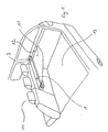
- FIG. 1 1 In an interior of a motor vehicle there is an installation unit in FIG. 1 1 detachably attached without tools.
- the installation unit 1 is in the Vehicle side wall 12 via a locking device 3 in a vehicle-fixed Holding device 2 locked in a force-transmitting manner and serves as a cassette housing for a load compartment cover 11.
- the load compartment cover 11 is used to separate a loading area 13 of the motor vehicle from a passenger area 14 and has a privacy function also a retention function for unsecured cargo.
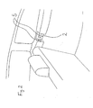
- the vehicle-fixed holding device 2 shown in FIG. 2 is on the vehicle side wall 12 is provided at the front end of the loading area 13.
- the vehicle-mounted holding device has several, in different Recesses 5 directed for the positive Engagement of the bolts 4, 4a, 4b, 4c, 4d, 7a, 7b.
- the locking device 3, 3a, 3b can according to the invention with different bolts 4, 4a, 4b, 4c, 4d, 7a, 7b.
- FIG. 3 shows a locking device which has three locking bars 4, one of which is arranged on the face of the installation unit 1, while two opposite bars 4 perpendicular to the main direction of extension the installation unit 1 are aligned. All in Fig. 3 bars 4 shown are linearly movable and have a bevel on the front, which is the insertion and locking in the Holding device 2 relieved. The latch 4 are on the actuator 6 controlled and for unlocking in the locking device 3 withdrawn.
- the locking and unlocking process of the latch shown in Fig. 3 can by positively acting actuating means 15c, 15d of the actuating unit be effected as shown in Figs. 8 and 9.
- the conical actuating means 15c shown in FIG Applying a torque to the vehicle user Actuating unit, not shown, causes the spindle 16c to rotate, which is supported in the locking device, also not shown and thus a combined translatory-rotary movement performs.
- the conical region of the actuating means 15c pressed on the back of the bars 4c and caused by a wedge effect a force on the bolt 4c, the spring force of the preloaded Counteracts spring elements 8c, so that a linear movement the bolt 4c is effected in the locking direction.
- FIG. 4 shows a locking device 3a, which has a locking bar 4a has, which is provided with two secondary bolts.
- the latch 4a and the Secondary bolts 7a are in a locking position for unlocking the secondary bolts 7a are first inserted linearly into the bolt 4a, the latch 4a can then also enter the latch device 3a be reduced linearly.
- the movement of the secondary bolts and the bolt can in a modification, not shown, of the in Fig. 6 and 7 shown actuation means.
- FIG. 5 shows a locking device 3b in which the locking bar 4b performs a linear bolt movement, while the secondary bolt 7b one Describe curve movement to achieve locking.
- Fig. 4 a fixed order of the bolt movement necessary to achieve safe locking and unlocking.
- the Actuating means 15b for the generation of a combined curve and Linear movements are shown in Figs. 6 and 7.
- Actuating means 15b in the form of are on the actuating element 6b Cables attached, which are connected to the secondary bolts 7b. In a 6 are almost the actuating means relaxed, whereby the bolt 4b and the secondary bolt 7b by the attached spring elements 8b pressed into the locking position become. The unlocking is effected by a torque is applied to the actuating element 6b. This will make the Cables wound on the actuator 6b and can thus exert a tensile force on the bolt and the secondary bolts.
- the spring forces of the spring elements 8b counteracting the tensile force are coordinated so that the secondary bolts 7b in Set movement and retract into latch 4b. Then it will be by further turning the actuating element 6b, the tensile force the bolt further increased, so that the counterforce of the spring element 8b of the bolt 4b can be overcome, whereby this moved into the locking device 3b.
- By compressing the spring elements 8b is the energy applied by the vehicle user saved and can be used for a new locking process become.
Landscapes
- Engineering & Computer Science (AREA)
- Mechanical Engineering (AREA)
- Lock And Its Accessories (AREA)
- Vehicle Step Arrangements And Article Storage (AREA)
Abstract
Description
- Fig. 1
- In perspektivischer Darstellung eine Innenansicht eines KombiKraftfahrzeuges mit verriegelter Einbaueinheit,
- Fig. 2
- in perspektivischer, vergrößerter Darstellung einen Ausschnitt aus dem Innenraum eines Kraftfahrzeuges,
- Fig. 3
- in perspektivischer Darstellung ein erstes Ausführungsbeispiel für eine Riegeleinrichtung mit drei Riegeln,
- Fig. 4
- in perspektivischer Darstellung ein zweites Ausführungsbeispiel für eine Riegeleinrichtung mit Riegel und linear bewegbarem Nebenriegel,
- Fig. 5
- in perspektivischer Darstellung ein drittes Ausführungsbeispiel für eine Riegeleinrichtung mit Riegel und rotatorisch ausschwenkendenden Nebenriegeln,
- Fig. 6
- in ebener Darstellung eine schematische Darstellung des dritten Ausführungsbeispiels für eine Riegelanordnung in Verriegelungsposition,
- Fig. 7
- in ebener Darstellung eine schematische Darstellung des dritten Ausführungsbeispiels für eine Riegelanordnung in Entriegelungsposition,
- Fig. 8
- in perspektivischer Darstellung eine erste Variante der Betätigungsmittel für das erste Ausführungsbeispiel einer Riegelanordnung und
- Fig. 9
- in perspektivischer Darstellung eine zweite Variante der Betätigungsmittel für das erste Ausführungsbeispiel einer Riegelanordnung.
Claims (12)
Applications Claiming Priority (2)
| Application Number | Priority Date | Filing Date | Title |
|---|---|---|---|
| DE10238613A DE10238613A1 (de) | 2002-08-19 | 2002-08-19 | Einbaueinheit für ein Kraftfahrzeug |
| DE10238613 | 2002-08-19 |
Publications (2)
| Publication Number | Publication Date |
|---|---|
| EP1393978A1 true EP1393978A1 (de) | 2004-03-03 |
| EP1393978B1 EP1393978B1 (de) | 2010-10-13 |
Family
ID=31197274
Family Applications (1)
| Application Number | Title | Priority Date | Filing Date |
|---|---|---|---|
| EP03018075A Expired - Lifetime EP1393978B1 (de) | 2002-08-19 | 2003-08-08 | Einbaueinheit für ein Kraftfahrzeug |
Country Status (5)
| Country | Link |
|---|---|
| US (1) | US6913303B2 (de) |
| EP (1) | EP1393978B1 (de) |
| JP (1) | JP2004076575A (de) |
| KR (1) | KR20040016781A (de) |
| DE (2) | DE10238613A1 (de) |
Cited By (1)
| Publication number | Priority date | Publication date | Assignee | Title |
|---|---|---|---|---|
| EP1600339A3 (de) * | 2004-05-25 | 2006-12-27 | REUM GmbH & Co. Betriebs KG | Aufnahmevorrichtung für ein Sicherheitsnetz |
Families Citing this family (19)
| Publication number | Priority date | Publication date | Assignee | Title |
|---|---|---|---|---|
| FR2884196B1 (fr) * | 2005-04-07 | 2007-06-01 | Wagon Sas | Dispositif cache-bagages pour vehicule automobile, et vehicule automobile correspondant |
| DE102005032470B3 (de) * | 2005-07-08 | 2007-03-08 | Bos Gmbh & Co. Kg | Laderaumschutzvorrichtung für ein Kraftfahrzeug |
| DE102005033819A1 (de) * | 2005-07-11 | 2007-01-25 | Bos Gmbh & Co. Kg | Laderaumschutzvorrichtung mit wenigstens einer Wickelwelle |
| DE102006005673B4 (de) * | 2006-02-01 | 2010-08-05 | Bos Gmbh & Co. Kg | Fahrzeugladeraum mit einer Laderaumabdeckung |
| KR100660127B1 (ko) * | 2006-06-23 | 2006-12-20 | 거호건설(주) | 도로의 차선 식별력 향상공법 및 도로의 구조 |
| US7779887B2 (en) * | 2007-01-10 | 2010-08-24 | Irvin Automotive Products, Inc. | Rotating end cap |
| US8672016B2 (en) * | 2007-01-10 | 2014-03-18 | Irvin Automotive Products, Inc. | Folding end cap |
| EP1946969B1 (de) * | 2007-01-19 | 2011-07-20 | Volvo Personvagnar AB | Gepäckraumabdeckung |
| US20090033114A1 (en) * | 2007-08-02 | 2009-02-05 | Thomas Steigerwald | Loading area cover for a motor vehicle |
| US7591296B2 (en) * | 2007-10-17 | 2009-09-22 | Irvin Automotive Products, Inc. | Two piece removable end cap |
| DE102009041691A1 (de) | 2009-09-16 | 2011-03-24 | GM Global Technology Operations, Inc., Detroit | Kraftfahrzeug mit Verriegelungseinrichtung für eine Kofferraumabdeckung |
| DE102012101770B4 (de) * | 2012-03-02 | 2021-09-23 | Dr. Ing. H.C. F. Porsche Aktiengesellschaft | Verriegelungsvorrichtung für ein Innenraumablagefach eines Kraftfahrzeugs |
| US8857850B2 (en) * | 2013-03-05 | 2014-10-14 | Harry Avanian | Cushioned barrier for pets in a vehicle |
| US20150083351A1 (en) * | 2013-09-24 | 2015-03-26 | Crestron Electronics, Inc. | Shade motor with latch assembly and bracket |
| GB2522417B (en) | 2014-01-22 | 2016-09-14 | Ford Global Tech Llc | Roll cover assembly |
| DE102014206551A1 (de) * | 2014-04-04 | 2015-10-08 | Bayerische Motoren Werke Aktiengesellschaft | Verriegelungseinrichtung in einem Fahrzeug und Fahrzeug mit einer derartigen Verriegelungseinrichtung |
| US9827839B2 (en) | 2014-10-31 | 2017-11-28 | Rugged Liner, Inc. | Tonneau cover system having a latch |
| DE102015100319B3 (de) * | 2015-01-12 | 2015-08-27 | Macauto Industrial Co., Ltd. | Laderaumabdeckung für ein Fahrzeug |
| FR3067675B1 (fr) * | 2017-06-19 | 2019-08-02 | Treves Products, Services & Innovation | Systeme d’actionnement en position de verrouillage d’une traverse de cache-bagages de compartiment a bagages de vehicule automobile |
Citations (4)
| Publication number | Priority date | Publication date | Assignee | Title |
|---|---|---|---|---|
| US4587695A (en) * | 1984-01-16 | 1986-05-13 | Irvin Industries Inc. | Snap-in latch mounting brackets |
| JPH0986280A (ja) * | 1995-09-22 | 1997-03-31 | Kasai Kogyo Co Ltd | 巻取り式トノカバーの装着構造 |
| DE29716241U1 (de) | 1997-09-10 | 1998-02-12 | Audi Ag, 85057 Ingolstadt | Laderaum-Trennvorrichtung für Kraftwagen, insbesondere für Kombinations-Personenkraftwagen |
| JPH10329610A (ja) * | 1997-05-30 | 1998-12-15 | Nissan Motor Co Ltd | トノカバー装置の取付装置 |
Family Cites Families (9)
| Publication number | Priority date | Publication date | Assignee | Title |
|---|---|---|---|---|
| US3578378A (en) * | 1969-04-11 | 1971-05-11 | Edwin G Anderson | Telescopic and pivotal cover assembly for open bed vehicles |
| US3944097A (en) * | 1974-02-05 | 1976-03-16 | B. J. Powell | Tree transporting vehicle |
| US3923334A (en) * | 1974-03-22 | 1975-12-02 | Hugh L Key | Vehicle bed cover assembly |
| US5350213A (en) * | 1993-03-12 | 1994-09-27 | Bernardo Richard G | Apparatus for positioning, latching and locking a retractable truck bed cover |
| DE4405280C2 (de) * | 1994-02-19 | 1996-05-30 | Baumeister & Ostler Gmbh Co | Abdeckrollo für Kombi-Personenkraftfahrzeuge |
| AUPM783794A0 (en) * | 1994-08-31 | 1994-09-22 | Rees Operations Pty Ltd | Improved safety barrier for motor vehicles |
| DE19930107C1 (de) * | 1999-07-01 | 2000-07-13 | Baumeister & Ostler Gmbh Co | Laderaumabtrennung für ein Kraftfahrzeug |
| US6343828B1 (en) * | 2000-07-10 | 2002-02-05 | David C. Young | Truck lid hinge and opener system |
| US6550849B1 (en) * | 2002-06-11 | 2003-04-22 | Ford Global Technologies, Inc. | Automotive vehicle with pass through cargo space |
-
2002
- 2002-08-19 DE DE10238613A patent/DE10238613A1/de not_active Withdrawn
-
2003
- 2003-08-08 DE DE50313173T patent/DE50313173D1/de not_active Expired - Lifetime
- 2003-08-08 EP EP03018075A patent/EP1393978B1/de not_active Expired - Lifetime
- 2003-08-09 KR KR1020030055224A patent/KR20040016781A/ko not_active Withdrawn
- 2003-08-18 US US10/643,007 patent/US6913303B2/en not_active Expired - Fee Related
- 2003-08-18 JP JP2003294207A patent/JP2004076575A/ja active Pending
Patent Citations (4)
| Publication number | Priority date | Publication date | Assignee | Title |
|---|---|---|---|---|
| US4587695A (en) * | 1984-01-16 | 1986-05-13 | Irvin Industries Inc. | Snap-in latch mounting brackets |
| JPH0986280A (ja) * | 1995-09-22 | 1997-03-31 | Kasai Kogyo Co Ltd | 巻取り式トノカバーの装着構造 |
| JPH10329610A (ja) * | 1997-05-30 | 1998-12-15 | Nissan Motor Co Ltd | トノカバー装置の取付装置 |
| DE29716241U1 (de) | 1997-09-10 | 1998-02-12 | Audi Ag, 85057 Ingolstadt | Laderaum-Trennvorrichtung für Kraftwagen, insbesondere für Kombinations-Personenkraftwagen |
Non-Patent Citations (2)
| Title |
|---|
| PATENT ABSTRACTS OF JAPAN vol. 1997, no. 07 31 July 1997 (1997-07-31) * |
| PATENT ABSTRACTS OF JAPAN vol. 1999, no. 03 31 March 1999 (1999-03-31) * |
Cited By (1)
| Publication number | Priority date | Publication date | Assignee | Title |
|---|---|---|---|---|
| EP1600339A3 (de) * | 2004-05-25 | 2006-12-27 | REUM GmbH & Co. Betriebs KG | Aufnahmevorrichtung für ein Sicherheitsnetz |
Also Published As
| Publication number | Publication date |
|---|---|
| DE10238613A1 (de) | 2004-03-11 |
| JP2004076575A (ja) | 2004-03-11 |
| US20040119307A1 (en) | 2004-06-24 |
| DE50313173D1 (de) | 2010-11-25 |
| EP1393978B1 (de) | 2010-10-13 |
| US6913303B2 (en) | 2005-07-05 |
| KR20040016781A (ko) | 2004-02-25 |
Similar Documents
| Publication | Publication Date | Title |
|---|---|---|
| EP1393978B1 (de) | Einbaueinheit für ein Kraftfahrzeug | |
| EP3899180B1 (de) | Aufstellvorrichtung für ein kraftfahrzeugtürelement | |
| DE69922373T2 (de) | Verschlussvorrichtung und haubenschloss für ein fahrzeug mit einer derartigen verschlussvorrichtung | |
| EP1899194B1 (de) | Vorrichtung zum verriegeln und entriegeln mit einer sicherung gegen selbstöffnung | |
| DE69936480T2 (de) | Elektrischer Schliessmechanismus mit einer zusätzlichen türinnenseitigen mechanischen Entriegelungseinrichtung | |
| EP1550784B1 (de) | Schliesskeil-Antriebsbaugruppe für ein Kraftfahrzeug-Türschloss | |
| DE60011523T2 (de) | Türschloss | |
| DE19635414A1 (de) | Schloß, insbesondere für Fahrzeugtüren oder dergleichen | |
| DE4028897C1 (en) | Motor vehicle boot flap lock - has spring loaded detent to prevent bolt being set if lid is open | |
| EP3915829B1 (de) | Fahrzeugsitzbeschlag und fahrzeugsitz | |
| DE102015204273A1 (de) | Fahrzeugsitz mit Easy-Entry-Funktion | |
| DE102020101806A1 (de) | Aufstellvorrichtung für eine Kraftfahrzeugtür | |
| DE102021131967A1 (de) | Sicherheitsbaugruppe zum Verhindern des Öffnens eines Fahrzeugschlosses bei vorgegebenen Fahrzeugzuständen | |
| EP2155999A1 (de) | Kraftfahrzeugtüranordnung | |
| EP1126106A1 (de) | Kraftfahrzeug-Türschloss mit kompaktem Aufbau | |
| DE102008006110B4 (de) | Verriegelungseinrichtung | |
| EP1057696B1 (de) | Überroll-Schutzsystem für Kraftfahrzeuge | |
| DE102021209345A1 (de) | Einrichtung zum Entriegeln eines Türschlosses einer Fahrzeugtür bei einem Unfall, Fahrzeugtür | |
| DE102008021923A1 (de) | Schließsystem für ein B-Säulen-freies Fahrzeug | |
| DE69806863T2 (de) | Öffnungsvorrichtung eines Kraftfahrzeugschlosses | |
| DE202007000733U1 (de) | Kraftfahrzeugschloß | |
| DE102021004899B3 (de) | Als modulares System aus wenigstens einem Modul aufgebaute manuelle Notentriegelungseinheit | |
| EP1034987B1 (de) | Überroll-Schutzvorrichtung fÜr Kraftfahrzeuge | |
| DE102005048659B4 (de) | Verstellmechanismus | |
| DE102019215589A1 (de) | Schlosseinrichtung für eine Fahrzeugtür, Schlossanordnung |
Legal Events
| Date | Code | Title | Description |
|---|---|---|---|
| PUAI | Public reference made under article 153(3) epc to a published international application that has entered the european phase |
Free format text: ORIGINAL CODE: 0009012 |
|
| AK | Designated contracting states |
Kind code of ref document: A1 Designated state(s): AT BE BG CH CY CZ DE DK EE ES FI FR GB GR HU IE IT LI LU MC NL PT RO SE SI SK TR |
|
| AX | Request for extension of the european patent |
Extension state: AL LT LV MK |
|
| 17P | Request for examination filed |
Effective date: 20040326 |
|
| AKX | Designation fees paid |
Designated state(s): DE FR GB SE |
|
| 17Q | First examination report despatched |
Effective date: 20050628 |
|
| 17Q | First examination report despatched |
Effective date: 20050628 |
|
| GRAP | Despatch of communication of intention to grant a patent |
Free format text: ORIGINAL CODE: EPIDOSNIGR1 |
|
| GRAS | Grant fee paid |
Free format text: ORIGINAL CODE: EPIDOSNIGR3 |
|
| GRAA | (expected) grant |
Free format text: ORIGINAL CODE: 0009210 |
|
| AK | Designated contracting states |
Kind code of ref document: B1 Designated state(s): DE FR GB SE |
|
| REG | Reference to a national code |
Ref country code: GB Ref legal event code: FG4D Free format text: NOT ENGLISH |
|
| REF | Corresponds to: |
Ref document number: 50313173 Country of ref document: DE Date of ref document: 20101125 Kind code of ref document: P |
|
| PG25 | Lapsed in a contracting state [announced via postgrant information from national office to epo] |
Ref country code: SE Free format text: LAPSE BECAUSE OF FAILURE TO SUBMIT A TRANSLATION OF THE DESCRIPTION OR TO PAY THE FEE WITHIN THE PRESCRIBED TIME-LIMIT Effective date: 20101013 |
|
| PLBE | No opposition filed within time limit |
Free format text: ORIGINAL CODE: 0009261 |
|
| STAA | Information on the status of an ep patent application or granted ep patent |
Free format text: STATUS: NO OPPOSITION FILED WITHIN TIME LIMIT |
|
| 26N | No opposition filed |
Effective date: 20110714 |
|
| REG | Reference to a national code |
Ref country code: DE Ref legal event code: R097 Ref document number: 50313173 Country of ref document: DE Effective date: 20110714 |
|
| GBPC | Gb: european patent ceased through non-payment of renewal fee |
Effective date: 20110808 |
|
| REG | Reference to a national code |
Ref country code: FR Ref legal event code: ST Effective date: 20120430 |
|
| PG25 | Lapsed in a contracting state [announced via postgrant information from national office to epo] |
Ref country code: FR Free format text: LAPSE BECAUSE OF NON-PAYMENT OF DUE FEES Effective date: 20110831 Ref country code: GB Free format text: LAPSE BECAUSE OF NON-PAYMENT OF DUE FEES Effective date: 20110808 |
|
| PGFP | Annual fee paid to national office [announced via postgrant information from national office to epo] |
Ref country code: DE Payment date: 20130830 Year of fee payment: 11 |
|
| REG | Reference to a national code |
Ref country code: DE Ref legal event code: R119 Ref document number: 50313173 Country of ref document: DE |
|
| REG | Reference to a national code |
Ref country code: DE Ref legal event code: R119 Ref document number: 50313173 Country of ref document: DE Effective date: 20150303 |
|
| PG25 | Lapsed in a contracting state [announced via postgrant information from national office to epo] |
Ref country code: DE Free format text: LAPSE BECAUSE OF NON-PAYMENT OF DUE FEES Effective date: 20150303 |