EP1391846A1 - Bildverarbeitungsverfahren, bildverarbeitungsvorrichtung und programm zur betonung der objektbewegung - Google Patents
Bildverarbeitungsverfahren, bildverarbeitungsvorrichtung und programm zur betonung der objektbewegung Download PDFInfo
- Publication number
- EP1391846A1 EP1391846A1 EP02778906A EP02778906A EP1391846A1 EP 1391846 A1 EP1391846 A1 EP 1391846A1 EP 02778906 A EP02778906 A EP 02778906A EP 02778906 A EP02778906 A EP 02778906A EP 1391846 A1 EP1391846 A1 EP 1391846A1
- Authority
- EP
- European Patent Office
- Prior art keywords
- image processing
- processing method
- movement
- pixels
- vertex
- Prior art date
- Legal status (The legal status is an assumption and is not a legal conclusion. Google has not performed a legal analysis and makes no representation as to the accuracy of the status listed.)
- Granted
Links
Images


Classifications
-
- G—PHYSICS
- G06—COMPUTING; CALCULATING OR COUNTING
- G06T—IMAGE DATA PROCESSING OR GENERATION, IN GENERAL
- G06T13/00—Animation
- G06T13/20—3D [Three Dimensional] animation
-
- A63F13/10—
-
- A—HUMAN NECESSITIES
- A63—SPORTS; GAMES; AMUSEMENTS
- A63F—CARD, BOARD, OR ROULETTE GAMES; INDOOR GAMES USING SMALL MOVING PLAYING BODIES; VIDEO GAMES; GAMES NOT OTHERWISE PROVIDED FOR
- A63F13/00—Video games, i.e. games using an electronically generated display having two or more dimensions
- A63F13/45—Controlling the progress of the video game
-
- A—HUMAN NECESSITIES
- A63—SPORTS; GAMES; AMUSEMENTS
- A63F—CARD, BOARD, OR ROULETTE GAMES; INDOOR GAMES USING SMALL MOVING PLAYING BODIES; VIDEO GAMES; GAMES NOT OTHERWISE PROVIDED FOR
- A63F13/00—Video games, i.e. games using an electronically generated display having two or more dimensions
- A63F13/50—Controlling the output signals based on the game progress
- A63F13/52—Controlling the output signals based on the game progress involving aspects of the displayed game scene
-
- A—HUMAN NECESSITIES
- A63—SPORTS; GAMES; AMUSEMENTS
- A63F—CARD, BOARD, OR ROULETTE GAMES; INDOOR GAMES USING SMALL MOVING PLAYING BODIES; VIDEO GAMES; GAMES NOT OTHERWISE PROVIDED FOR
- A63F2300/00—Features of games using an electronically generated display having two or more dimensions, e.g. on a television screen, showing representations related to the game
- A63F2300/60—Methods for processing data by generating or executing the game program
- A63F2300/66—Methods for processing data by generating or executing the game program for rendering three dimensional images
- A63F2300/6692—Methods for processing data by generating or executing the game program for rendering three dimensional images using special effects, generally involving post-processing, e.g. blooming
-
- A—HUMAN NECESSITIES
- A63—SPORTS; GAMES; AMUSEMENTS
- A63F—CARD, BOARD, OR ROULETTE GAMES; INDOOR GAMES USING SMALL MOVING PLAYING BODIES; VIDEO GAMES; GAMES NOT OTHERWISE PROVIDED FOR
- A63F2300/00—Features of games using an electronically generated display having two or more dimensions, e.g. on a television screen, showing representations related to the game
- A63F2300/80—Features of games using an electronically generated display having two or more dimensions, e.g. on a television screen, showing representations related to the game specially adapted for executing a specific type of game
- A63F2300/8029—Fighting without shooting
Definitions
- the present invention relates generally to an image processing method using three-dimensional computer graphics (CG), and more particularly to an image processing method for more efficiently displaying movements of objects made up of polygons.
- CG three-dimensional computer graphics
- images are displayed on a computer game apparatus screen that are created by projecting objects, including characters such as humans and animals arranged in a virtual three-dimensional space, onto a given two dimensional plane.
- objects including characters such as humans and animals arranged in a virtual three-dimensional space, onto a given two dimensional plane.
- Objects are, for example, made up of a plurality of polygons.
- These objects can move within the virtual three-dimensional space, for example, through players' operations, with the movements of the objects accordingly shown on the computer screen.
- moving objects are displayed by displacing backward given vertices of polygons making up the moving objects, imparting an afterimage representation to the objects that representation makes the objects look as if they leave a trail in the direction opposite to their direction of movement. This allows for display of movements of the objects in a more emphasized manner and display of the moving objects with richer expression.
- a first image processing method of the present invention to achieve the above object is an image processing method for displaying an object, composed of a plurality of polygons, moving in a virtual three-dimensional space, the method comprising the steps of acquiring, at every given sampling timing, coordinates of at least one vertex, whose normal vector has a component opposite to a movement direction vector of the object, among vertices of the polygons composing the object; and displaying the polygon having the at least one vertex assuming that coordinates of the at least one vertex are located at a position displaced by a given length in a direction having the component opposite to the movement direction.
- a second image processing method of the present invention is an image processing method according to the first method, further comprising the step of determining, based on an inner product of the normal vector of each vertex and the movement direction vector of the object, whether the normal vector of each vertex has the component opposite to the movement direction vector.
- a third image processing method of the present invention is an image processing method wherein the given length is determined based on at least one of the object's distance of movement, velocity of movement, acceleration of movement and direction of movement.
- a fourth image processing method of the present invention is an image processing method according to the first or the second method, wherein the given length is determined based on coordinates at a current sampling timing and on coordinates at a last sampling timing.
- a fifth image processing method of the present invention is an image processing method according to the first or the second method, wherein the given length is determined based on a magnitude of the movement direction vector.
- a sixth image processing method of the present invention is an image processing method according to the fourth or the fifth method, wherein the given length is determined further in consideration of the inner product of the normal vector of each vertex and the movement direction vector of the object.
- a seventh image processing method of the present invention is an image processing method according to any one of the fourth to sixth methods, wherein the given length is determined further in consideration of a displacement ratio imparted to each vertex.
- An eighth image processing method of the present invention is an image processing method according to the seventh method, wherein the displacement ratio is set to different values for each vertices.
- a ninth image processing method of the present invention is an image processing method according to the seventh or the eighth method, further comprising the step of setting a transparency level set for the vertices to a value obtained by subtracting the displacement ratio of each vertex from a preset value.
- a tenth image processing method of the present invention is an image processing method according to the first method, further comprising the step of setting a transparency level set for the vertices to a value lower than a preset value.
- An eleventh image processing method of the present invention is an image processing method according to the tenth method, wherein the transparency level set for the vertices is set to the value obtained by subtracting from a preset transparency level an absolute value of the inner product of the normal vector of each vertex and the movement direction vector of the object.
- a twelfth image processing method of the present invention is an image processing method according to the first method, wherein the displayed polygons are displayed such that at least one of transparency level, saturation, lightness and hue changes with change in distance to the vertex.
- a thirteenth image processing method of the present invention is an image processing method according to the twelfth method, wherein a magnitude of the change is determined based on at least one of the object's distance of movement, velocity of movement, acceleration of movement and direction of movement.
- a program is also provided for causing a computer apparatus to execute the steps of any one of the first to thirteenth image processing methods.
- An image processing apparatus is also provided for executing any one of the first to thirteenth image processing methods.
- Fig. 1 illustrates an appearance of a computer game apparatus (game unit) that is an image processing apparatus of an embodiment of the present invention.
- Fig. 1 shows a case in which two identical game units are connected together.
- a display 2 shows a virtual three-dimensional space in which characters C1 and C2 are placed as shown in Figs. 2A and 2B.
- the player While watching a game screen appearing on the display 2, the player, for example, moves the character C1 by operating it, for example, to fight against the other character C2 using operating sections 3 that are levers equipped with buttons.
- Fig. 3 illustrates a block diagram showing an example of configuration of a game unit according to the present invention incorporated in the computer game apparatus.
- An area 10 enclosed by a dotted line in Fig. 3 represents a portion accommodated in the main body of the game unit.
- various constituent elements described below such as CPU are connected via a bus 100.
- a CPU 101 controls program execution based on a game program stored in a ROM 102.
- the ROM 102 is used as a generic name for program storage devices and includes, for example, a harddisk drive and an optical disk drive that reads an optical disk storing the program.
- a RAM 103 given game parameters updated with the progress of the game such as characters' coordinates in a virtual space are stored.
- the geometry processing section 104 obtains vertex data (including coordinates) for characters and polygons making up the background in the game's three-dimensional virtual space at every given sampling timing (1/60 second) and performs given coordinate conversion processings described later based on the vertex data.
- vertex data including coordinates
- polygon coordinates in a world coordinate system set in a three-dimensional virtual space are converted to a viewpoint coordinate system which determines how the polygon coordinates are expressed when someone sees the virtual space from a certain point in the world coordinate system.
- a rendering processing section 105 is connected to the geometry processing section 104.
- a texture buffer 106 is connected to the rendering processing section 105.
- data such as the polygon vertex data and data of textures mapped onto such polygons, which data are loaded from the ROM (program storage device) 102 are temporarily stored.
- the rendering processing section 105 performs processings such as adding colors to, shading and pasting textures to polygons based on polygon texture data stored in the texture buffer 106.
- the rendering processing section 105 converts polygon coordinates, converted to the viewpoint coordinate system in the three-dimensional virtual space, to a two dimensional coordinate system for display on the display 2.
- Z buffer 107 connected to the rendering processing section 105, data information (e.g., which polygon is to be placed to the front) regarding the direction of depth (Z direction) used during conversion of the polygon coordinates from three-dimensional to two dimensional coordinate systems are stored.
- a frame buffer 108 is connected to the output side of the rendering processing section 105.
- a screenful of data to be displayed on the display 2 are stored.
- the screenful of image data loaded from the frame buffer 108 is converted to video signal by a video processing section 109 and displayed in succession on the display 2.
- the CPU 101 computes characters' and other coordinates in the virtual space based on operation signals input from the operating sections 3, after which computation results are sent to the geometry processing section 104.
- a sound processing section 111 is further connected to the bus 100, controlling the pronunciation of a PCM/FM sound source.
- a sound memory 112 is connected to the sound processing section 111 for storing voice data.
- voice data controlled by the sound processing section 111 is converted from digital to analog sound sources by a D/A converter circuit not shown, sending audio signal to a speaker 113.
- character positions in the game virtual space are given in position coordinates (X W , Y W , Z W ) in the three-dimensional coordinates (world coordinate system) in the virtual space.
- Positions of the background such as fixed objects other than characters in the virtual space are also given in position coordinates in the world coordinate system. Movements of characters in the virtual space are processed as changes to position coordinates in the world coordinate system.
- character position coordinates W are computed by the CPU 101's computation based on information on the distance and the direction of movement contained in operation signals from the operating sections 3 and others.
- images are shown on the display 2 as two dimensional images seen in a given direction from coordinates of a given point (viewpoint coordinates) in the world coordinate system in the three-dimensional virtual space. This makes players feel as if images captured by a video camera, installed at a given position in the virtual space, are shown on the display.
- character position coordinates are determined by the position coordinates (X W , Y W , Z W ) in the world coordinate system.
- the viewpoint coordinates P (X W P, Y W P, Z W P) are, for example, set at viewpoint coordinates P in the back of and diagonally above the character C1 in the world coordinate system while a direction of line of sight R from the viewpoint coordinates P is, for example, set in the direction of coordinates Q (X W Q, Y W Q, Z W Q) of a gazing point close to and above the character C1 (e.g., a position slightly higher than the head of the character C1) as shown in Fig. 4.
- the position of the viewpoint coordinates P is marked "V" to represent a virtual video camera.
- Coordinates of characters and others in the world coordinate system are converted by the geometry processing section 104 to a viewpoint coordinate system (X v , Y v , Z v ) that is based on the viewpoint coordinates P and the direction of line of sight R and further converted.by the rendering processing section 105 shown in Fig. 3 to a two dimensional screen coordinate system (Xs, Ys) through given projection conversion processing for display of two dimensional images on the display 2.
- Embodiments of the present invention provide image processing methods for more effectively displaying movements of objects including characters on the display when such objects move within the three-dimensional virtual space. More specifically, to display movements of moving objects in a more emphasized manner, afterimage display processing is performed that makes the objects look as if they leave a trail in the direction opposite to their movements.
- Figs. 5A and 5B illustrate examples of objects displayed by an image processing method in an embodiment of the present invention.
- a spherical object shown in Fig. 5A moves, an afterimage of the object appears that looks as if the object leaves a trail in the direction opposite to its movement as shown in Fig. 5B, further emphasizing the sphere movement.
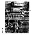
- Figs. 6A, 6B, 7A and 7B illustrate examples of computer game screens using image processing methods in embodiments of the present invention.
- Figs. 6A and 7A illustrate examples of screens with the moving characters C not subjected to afterimage display processing while Figs. 6B and 7B examples of screens with the characters C subjected to afterimage display processing.
- a given polygon or polygons that make up an object are extended in embodiments of the present invention to display an afterimage together with the object.
- Fig. 8 illustrates a diagrammatic sketch of an image processing method in an embodiment of the present invention.
- a plurality of polygons making up a sphere are shown in Fig. 8.
- a normal vector N1 is opposite to the direction of movement of an object as in the case of a vertex P1 of a polygon A shown in Fig. 8, for example, coordinates of the vertex P1 obtained at every given sampling timing are treated as coordinates VB1 at the last timing rather than coordinates V1 at the current timing during rendering processing.
- coordinates in the image processing methods explained below may be a world coordinate system or viewpoint coordinate system.
- a processing is performed to displace backward polygon vertices in the direction opposite to the direction of movement of the objects.
- vertices are selected from among all polygon vertices by the following processing:
- the movement direction vector MV can be found from changes in vertex coordinates of one or a plurality of given polygons making up the object. It is preferred that the vertex or vertices of a given polygon or polygons of a non-rotating part, for example, of the torso be chosen if the character is a human.
- the movement direction vector MV may be a unit vector.
- the normal vector NVn of each vertex corresponding to the movement direction vector MV is found by correcting, based on each change in the posture (rotation angle in the case of rotation), the normal vector NVn of each polygon into the normal vector NVn of the vertex in the reference state in which the character is upright.
- the normal vector NVn may be a unit vector.
- An angle difference between the movement direction vector MV and each of the normal vectors NVn can be found by finding the inner product IPn. More specifically, if the inner product IPn is 1, the angle difference is 0 (zero) degree. That is, the movement direction vector MV and the normal vector NVn are in the same direction. If the inner product IPn is -1, the angle difference is 180 degrees. That is, the movement direction vector MV and the normal vector NVn are pointing in exactly opposite directions. If the inner product IPn is 0 (zero), the angle difference is 90 degrees. That is, the movement direction vector MV and the normal vector NVn are orthogonal to each other.
- vertices whose inner product IPn is 0 (zero) or more will not be subjected to backward displacement processing since they have a direction component in the same direction as the direction of movement. These vertices are displayed using their coordinates at the current sampling timing as is.
- vertices whose inner product IPn is less than 0 (zero) will be selected as vertices to be subjected to backward displacement processing since they have a direction component opposite to the direction of movement.
- the latter half of the vertices in the moving object are subjected to backward displacement processing with respect to the direction of movement, with polygons containing those vertices being extended.
- Vertex coordinates at the current and last timings among given sampling timings are assumed to be Vn and VBn, respectively.
- a displacement ratio Rn used in the equations shown below may be defined.
- the given displacement ratio Rn for extending each polygon is given to the vertex of each polygon.
- the displacement ratio Rn can be set in the range 0 to 1.
- the same value or different values may be given to vertices. If different values are given, they may be randomly given by a program or those values specified by the programmer during program creation may be given.
- Vertex coordinates (VBn - Vn) x Rn + Vn
- Fig. 9A and 9B illustrate examples of objects displayed based on vertex coordinates displaced backward.
- Fig. 9A illustrates a diagrammatic sketch of an example of object displayed according to the equation [1], in which if the displacement ratios Rn are the same, vertices are displaced by the same length, that is, polygons are extended by the same length.
- Rn displacement ratios
- vertices are displaced by the same length, that is, polygons are extended by the same length.
- normal vectors (shown by arrows) of vertices P1, P2, P3 and P4 are displaced by the same length or L although they are pointing in different directions.
- Vertex coordinates (VBn - Vn) x Rn x (-IPn) + Vn
- Fig. 9B illustrates an example of object displayed according to the equation [2], in which vertex backward displacement lengths are different according to the angle difference between the normal vector NVn and the movement direction vector MV, thus making the displayed afterimage look more natural.
- normal vectors shown by arrows
- the vertices P1 and P4 whose difference in angle with the direction of movement is relatively small, undergo a shorter displacement than the vertices P2 and P3 having a relatively large angle difference (L1 ⁇ L2).
- Vertex coordinates (-MV) x Rn + Vn
- vertex coordinates are determined vertex by vertex based on the coordinates at the current timing Vn and the coordinates at the last timing VBn, however the same magnitude of the movement direction vector MV, that is, the object's distance or velocity of movement (except when the movement direction vector is a unit vector), is used indiscriminately for all vertices in the equation [3] and next equation [4], thus reducing the amount of calculations needed.
- This equation yields the same result as equation [1] if vertices are displaced by the same distance between sampling timings and if the distance is equal to the magnitude of the movement direction vector MV.
- Vertex coordinates (-MV) x Rn x (-IPn) + Vn
- Backward displacement length can be obtained according to the difference in angle with the movement direction vector, by taking the inner product IPn into consideration as is done in equation [2].
- This equation yields the same result as equation [2] if vertices are displaced by the same distance between sampling timings and if the distance is equal to the magnitude of the movement direction vector MV.
- the displacement length may be, for example, determined based on the object's acceleration or direction of movement in addition to the above.
- a rearward portion of an object can be displayed to look as if the portion leaves a trail by displacing polygon vertices backward during rendering processing, thus allowing for more effective display of the object movement.
- a transparency level ⁇ of vertices displaced backward is adjusted.
- a vertex is fully opaque when the transparency level ⁇ is 1 and fully transparent when the transparency level ⁇ is 0 (zero).
- the preset transparency level ⁇ for vertices of polygons making up an object is 1 (fully opaque), and in the embodiment the transparency level ⁇ is determined according to the backward displacement length. Note, however, that the preset transparency level ⁇ need not be 1.
- Fig. 10 illustrates a drawing showing the state in which the transparency level of polygons, extended backward from an object, changes gradually. As shown in Fig. 10, it is possible to display the object movement more naturally and effectively by ensuring that the extended polygon A increases in transparency level ⁇ with increase in distance from the object. Note that the transparency level ⁇ is indicated by the distance between oblique lines in Fig. 10. Although the transparency level ⁇ changes at separated region in Fig. 10 for reasons of convenience, the level practically changes in a continuous manner.
- the direction in which to display the object afterimage is not limited to the direction opposite to the object's direction of movement, and those directions having a direction component in the opposite direction to the object's movement direction may be used such as a slanted direction on the opposite side of the object's direction of movement.
- changes are not limited to the transparency level set for displaced vertices as in the above embodiment, and saturation, lightness, brightness or hue set for displaced vertices may be changed.
- the extent of change may be determined according to the displacement ratio or normal vector direction (inner product) as discussed above or according to the object's distance, velocity, acceleration or direction of movement.
- the polygon extension processing (afterimage display processing) in the embodiment need not be targeted for whole polygons making up an object.
- the processing may be applied to only some parts of polygons making up an object.
- the image processing method of the present embodiment may be applied only to "attacking arm parts" or “most vigorously moving parts” of human characters in a multi-player fighting game or to polygons of "taillight parts" of car characters in an auto racing game.
- the deformed polygon may be displayed superposed on the object. This makes it possible to superpose a deformed object as an afterimage object on the original object rather than deform the original object itself.
- pixels making up an object can be moved or extended in the direction opposite to the object's direction of movement.
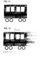
- Figs. 11 to 17 illustrate explanatory diagrams of an embodiment of the present invention in which pixels making up an object are moved or extended in the direction opposite to the object's direction of movement.
- Fig. 11 illustrates the state in which the object is at rest or moving slowly, showing an image of two dimensional vehicle made up of a set of pixels.
- Fig. 12 shows that pixels are extended, according to the present invention, from an arbitrary reference point (near center CP of the object as a working example) of the object (showing a vehicle as moving body) in the direction having vectors opposite to the movement direction MD.
- an afterimage is represented by extending pixels without changing the object shape, thus effectively representing the object movement. Note that it is possible to impart more sense of speed to the object movement by, as a pixel extension method, not only simply adding or copying pixels in the direction opposite to the object's movement direction as shown in Fig. 12 but also undisplaying pixels making up object portions corresponding to the added portion.
- the present method is applicable to not only two dimensional images as shown in Fig. 11 but also to three-dimensional images, that is, by extending pixels making up polygons.
- Figs. 13 and 14 show working examples in which an arbitrary reference point is placed at the front-half portion of the object.
- Fig. 15 illustrates a working example in which an arbitrary reference point is placed at the rear-half portion of the object.
- FIG. 16 shows afterimage processing performed only on outlines extracted from portions for which afterimage is to be produced.
- the image processing apparatus that carries out the image processing methods in the aforementioned embodiments of the present invention, is not limited to computer game apparatuses provided in amusement facilities as shown in Fig. 1 and may be, for example, a home use computer game apparatus.
Applications Claiming Priority (3)
| Application Number | Priority Date | Filing Date | Title |
|---|---|---|---|
| JP2001146309 | 2001-05-16 | ||
| JP2001146309 | 2001-05-16 | ||
| PCT/JP2002/004753 WO2002101655A1 (fr) | 2001-05-16 | 2002-05-16 | Procede et appareil de traitement d'image, et programme pour accentuer le mouvement d'un objet |
Publications (3)
| Publication Number | Publication Date |
|---|---|
| EP1391846A1 true EP1391846A1 (de) | 2004-02-25 |
| EP1391846A4 EP1391846A4 (de) | 2006-03-29 |
| EP1391846B1 EP1391846B1 (de) | 2011-10-19 |
Family
ID=18991982
Family Applications (1)
| Application Number | Title | Priority Date | Filing Date |
|---|---|---|---|
| EP02778906A Expired - Lifetime EP1391846B1 (de) | 2001-05-16 | 2002-05-16 | Bildverarbeitungsverfahren, bildverarbeitungsvorrichtung und programm zur betonung der objektbewegung |
Country Status (3)
| Country | Link |
|---|---|
| US (1) | US7116329B2 (de) |
| EP (1) | EP1391846B1 (de) |
| WO (1) | WO2002101655A1 (de) |
Cited By (14)
| Publication number | Priority date | Publication date | Assignee | Title |
|---|---|---|---|---|
| WO2005106801A1 (ja) | 2004-04-29 | 2005-11-10 | Konami Digital Entertainment Co., Ltd. | 画像生成装置、速度表現方法、および、プログラム |
| WO2010005802A3 (en) * | 2008-07-11 | 2010-05-27 | Medtronic, Inc. | Posture state classification for a medical device |
| US8570308B2 (en) | 2006-05-17 | 2013-10-29 | Yazaki Corporation | Graphic meter display |
| EP2365293A4 (de) * | 2008-12-08 | 2017-01-25 | Yazaki Corporation | Einrichtung zum zeichnen eines zu bewegenden bildes und anzeigesystem für ein fahrzeug |
| US9662045B2 (en) | 2008-07-11 | 2017-05-30 | Medtronic, Inc. | Generation of sleep quality information based on posture state data |
| US9737719B2 (en) | 2012-04-26 | 2017-08-22 | Medtronic, Inc. | Adjustment of therapy based on acceleration |
| US9907959B2 (en) | 2012-04-12 | 2018-03-06 | Medtronic, Inc. | Velocity detection for posture-responsive therapy |
| US9919159B2 (en) | 2008-07-11 | 2018-03-20 | Medtronic, Inc. | Programming posture responsive therapy |
| US9956412B2 (en) | 2008-07-11 | 2018-05-01 | Medtronic, Inc. | Linking posture states for posture responsive therapy |
| US9956418B2 (en) | 2010-01-08 | 2018-05-01 | Medtronic, Inc. | Graphical manipulation of posture zones for posture-responsive therapy |
| US10071197B2 (en) | 2009-04-30 | 2018-09-11 | Medtronic, Inc. | Therapy system including multiple posture sensors |
| US10130815B2 (en) | 2003-09-15 | 2018-11-20 | Medtronic, Inc. | Automatic therapy adjustments |
| US10207118B2 (en) | 2008-07-11 | 2019-02-19 | Medtronic, Inc. | Associating therapy adjustments with posture states using a stability timer |
| US10471264B2 (en) | 2005-12-02 | 2019-11-12 | Medtronic, Inc. | Closed-loop therapy adjustment |
Families Citing this family (17)
| Publication number | Priority date | Publication date | Assignee | Title |
|---|---|---|---|---|
| CN100350351C (zh) * | 2002-03-08 | 2007-11-21 | 设计展示公司 | 电装置控制设备 |
| JP4148868B2 (ja) * | 2003-10-08 | 2008-09-10 | 任天堂株式会社 | ゲームプログラムおよびゲーム装置 |
| US9050471B2 (en) | 2008-07-11 | 2015-06-09 | Medtronic, Inc. | Posture state display on medical device user interface |
| US8708934B2 (en) | 2008-07-11 | 2014-04-29 | Medtronic, Inc. | Reorientation of patient posture states for posture-responsive therapy |
| US8332041B2 (en) | 2008-07-11 | 2012-12-11 | Medtronic, Inc. | Patient interaction with posture-responsive therapy |
| US8200340B2 (en) | 2008-07-11 | 2012-06-12 | Medtronic, Inc. | Guided programming for posture-state responsive therapy |
| US8280517B2 (en) | 2008-09-19 | 2012-10-02 | Medtronic, Inc. | Automatic validation techniques for validating operation of medical devices |
| US9327070B2 (en) | 2009-04-30 | 2016-05-03 | Medtronic, Inc. | Medical device therapy based on posture and timing |
| US8175720B2 (en) | 2009-04-30 | 2012-05-08 | Medtronic, Inc. | Posture-responsive therapy control based on patient input |
| US9357949B2 (en) | 2010-01-08 | 2016-06-07 | Medtronic, Inc. | User interface that displays medical therapy and posture data |
| US8758274B2 (en) | 2010-01-08 | 2014-06-24 | Medtronic, Inc. | Automated adjustment of posture state definitions for a medical device |
| US8579834B2 (en) | 2010-01-08 | 2013-11-12 | Medtronic, Inc. | Display of detected patient posture state |
| US9566441B2 (en) | 2010-04-30 | 2017-02-14 | Medtronic, Inc. | Detecting posture sensor signal shift or drift in medical devices |
| JP5632657B2 (ja) * | 2010-06-09 | 2014-11-26 | 任天堂株式会社 | 画像処理プログラム、画像処理装置、画像処理システム及び画像処理方法 |
| US10289204B2 (en) * | 2012-11-15 | 2019-05-14 | Quantum Interface, Llc | Apparatuses for controlling electrical devices and software programs and methods for making and using same |
| US10503359B2 (en) * | 2012-11-15 | 2019-12-10 | Quantum Interface, Llc | Selection attractive interfaces, systems and apparatuses including such interfaces, methods for making and using same |
| JP6407460B1 (ja) * | 2018-02-16 | 2018-10-17 | キヤノン株式会社 | 画像処理装置、画像処理方法およびプログラム |
Citations (2)
| Publication number | Priority date | Publication date | Assignee | Title |
|---|---|---|---|---|
| EP1085472A2 (de) * | 1999-09-14 | 2001-03-21 | Sony Computer Entertainment Inc. | Verfahren zur Bildrahmenerzeugung, Speichermedium und Gerät zur Programmausführung |
| US20020027555A1 (en) * | 2000-06-28 | 2002-03-07 | Kenichi Mori | Method of rendering motion blur image and apparatus therefor |
Family Cites Families (12)
| Publication number | Priority date | Publication date | Assignee | Title |
|---|---|---|---|---|
| JP3150473B2 (ja) * | 1993-02-10 | 2001-03-26 | 富士通株式会社 | 表示制御装置および情報処理装置 |
| JPH0793586A (ja) * | 1993-06-30 | 1995-04-07 | Nippon Steel Corp | 3次元コンピュータグラフィックスアニメーションにおいてモーションブラーを表現する方法 |
| JP4067138B2 (ja) * | 1994-06-07 | 2008-03-26 | 株式会社セガ | ゲーム装置 |
| JPH08320949A (ja) * | 1995-05-24 | 1996-12-03 | Sega Enterp Ltd | 画像処理装置及びそれを用いたゲーム装置 |
| JP3871224B2 (ja) * | 1995-12-07 | 2007-01-24 | 株式会社セガ | 画像生成装置、画像生成方法及びこれを用いたゲーム機並びに媒体 |
| JPH1139502A (ja) * | 1997-05-23 | 1999-02-12 | Sega Enterp Ltd | 画像表示装置、その方法および記録媒体 |
| JP4129651B2 (ja) * | 1998-04-17 | 2008-08-06 | 株式会社セガ | 画像処理装置、ゲーム装置、画像処理方法および記録媒体 |
| JP4114825B2 (ja) * | 1998-04-24 | 2008-07-09 | 株式会社バンダイナムコゲームス | 画像生成装置及び情報記憶媒体 |
| JP2000200361A (ja) * | 1998-08-07 | 2000-07-18 | Sega Enterp Ltd | 画像処理装置及び情報記録媒体 |
| JP4464475B2 (ja) * | 1998-10-07 | 2010-05-19 | 株式会社バンダイナムコゲームス | ゲーム装置及び情報記憶媒体 |
| US6456289B1 (en) * | 1999-04-23 | 2002-09-24 | Georgia Tech Research Corporation | Animation system and method for a animating object fracture |
| JP3321570B2 (ja) * | 1999-09-14 | 2002-09-03 | 株式会社ソニー・コンピュータエンタテインメント | 動画作成方法、記憶媒体およびプログラム実行装置 |
-
2002
- 2002-05-16 WO PCT/JP2002/004753 patent/WO2002101655A1/ja active Application Filing
- 2002-05-16 EP EP02778906A patent/EP1391846B1/de not_active Expired - Lifetime
-
2003
- 2003-11-12 US US10/704,830 patent/US7116329B2/en not_active Expired - Lifetime
Patent Citations (2)
| Publication number | Priority date | Publication date | Assignee | Title |
|---|---|---|---|---|
| EP1085472A2 (de) * | 1999-09-14 | 2001-03-21 | Sony Computer Entertainment Inc. | Verfahren zur Bildrahmenerzeugung, Speichermedium und Gerät zur Programmausführung |
| US20020027555A1 (en) * | 2000-06-28 | 2002-03-07 | Kenichi Mori | Method of rendering motion blur image and apparatus therefor |
Non-Patent Citations (1)
| Title |
|---|
| See also references of WO02101655A1 * |
Cited By (26)
| Publication number | Priority date | Publication date | Assignee | Title |
|---|---|---|---|---|
| US10130815B2 (en) | 2003-09-15 | 2018-11-20 | Medtronic, Inc. | Automatic therapy adjustments |
| EP1744283A1 (de) * | 2004-04-29 | 2007-01-17 | Konami Digital Entertainment Co., Ltd. | Bilderzeugungseinrichtung, geschwindigkeits-express-verfahren und programm |
| EP1744283A4 (de) * | 2004-04-29 | 2009-04-15 | Konami Digital Entertainment | Bilderzeugungseinrichtung, geschwindigkeits-express-verfahren und programm |
| US7985136B2 (en) | 2004-04-29 | 2011-07-26 | Konomi Digital Entertainment Co., Ltd. | Image producing device, speed expressing method, and program |
| WO2005106801A1 (ja) | 2004-04-29 | 2005-11-10 | Konami Digital Entertainment Co., Ltd. | 画像生成装置、速度表現方法、および、プログラム |
| US10471264B2 (en) | 2005-12-02 | 2019-11-12 | Medtronic, Inc. | Closed-loop therapy adjustment |
| DE102007022534B4 (de) * | 2006-05-17 | 2015-11-19 | Yazaki Corporation | Graphisches Instrumentendisplay |
| US8570308B2 (en) | 2006-05-17 | 2013-10-29 | Yazaki Corporation | Graphic meter display |
| US9776008B2 (en) | 2008-07-11 | 2017-10-03 | Medtronic, Inc. | Posture state responsive therapy delivery using dwell times |
| US10231650B2 (en) | 2008-07-11 | 2019-03-19 | Medtronic, Inc. | Generation of sleep quality information based on posture state data |
| US9662045B2 (en) | 2008-07-11 | 2017-05-30 | Medtronic, Inc. | Generation of sleep quality information based on posture state data |
| US11672989B2 (en) | 2008-07-11 | 2023-06-13 | Medtronic, Inc. | Posture state responsive therapy delivery using dwell times |
| US8958885B2 (en) | 2008-07-11 | 2015-02-17 | Medtronic, Inc. | Posture state classification for a medical device |
| US11004556B2 (en) | 2008-07-11 | 2021-05-11 | Medtronic, Inc. | Associating therapy adjustments with posture states using a stability timer |
| US9919159B2 (en) | 2008-07-11 | 2018-03-20 | Medtronic, Inc. | Programming posture responsive therapy |
| US9956412B2 (en) | 2008-07-11 | 2018-05-01 | Medtronic, Inc. | Linking posture states for posture responsive therapy |
| US10925517B2 (en) | 2008-07-11 | 2021-02-23 | Medtronic, Inc. | Posture state redefinition based on posture data |
| US9968784B2 (en) | 2008-07-11 | 2018-05-15 | Medtronic, Inc. | Posture state redefinition based on posture data |
| WO2010005802A3 (en) * | 2008-07-11 | 2010-05-27 | Medtronic, Inc. | Posture state classification for a medical device |
| EP2656787A1 (de) * | 2008-07-11 | 2013-10-30 | Medtronic Inc. | Haltungszustandsklassifizierung für eine medizinische Vorrichtung |
| US10207118B2 (en) | 2008-07-11 | 2019-02-19 | Medtronic, Inc. | Associating therapy adjustments with posture states using a stability timer |
| EP2365293A4 (de) * | 2008-12-08 | 2017-01-25 | Yazaki Corporation | Einrichtung zum zeichnen eines zu bewegenden bildes und anzeigesystem für ein fahrzeug |
| US10071197B2 (en) | 2009-04-30 | 2018-09-11 | Medtronic, Inc. | Therapy system including multiple posture sensors |
| US9956418B2 (en) | 2010-01-08 | 2018-05-01 | Medtronic, Inc. | Graphical manipulation of posture zones for posture-responsive therapy |
| US9907959B2 (en) | 2012-04-12 | 2018-03-06 | Medtronic, Inc. | Velocity detection for posture-responsive therapy |
| US9737719B2 (en) | 2012-04-26 | 2017-08-22 | Medtronic, Inc. | Adjustment of therapy based on acceleration |
Also Published As
| Publication number | Publication date |
|---|---|
| EP1391846B1 (de) | 2011-10-19 |
| US7116329B2 (en) | 2006-10-03 |
| US20040095353A1 (en) | 2004-05-20 |
| EP1391846A4 (de) | 2006-03-29 |
| WO2002101655A1 (fr) | 2002-12-19 |
Similar Documents
| Publication | Publication Date | Title |
|---|---|---|
| US7116329B2 (en) | Image processing method | |
| US5966132A (en) | Three-dimensional image synthesis which represents images differently in multiple three dimensional spaces | |
| EP1033682B1 (de) | Bildverarbeitungsgerät und -verfahren | |
| US20090244064A1 (en) | Program, information storage medium, and image generation system | |
| US8647197B2 (en) | Storage medium storing game program and game apparatus | |
| US6667741B1 (en) | Image generating device and image generating method | |
| JP2006092156A (ja) | プログラム、情報記憶媒体及び画像生成装置 | |
| JP2011258160A (ja) | プログラム、情報記憶媒体及び画像生成システム | |
| JP3420870B2 (ja) | 画像合成方法、画像合成装置及びゲーム装置 | |
| JP4305903B2 (ja) | 画像生成システム、プログラム及び情報記憶媒体 | |
| JP4053078B2 (ja) | 3次元ゲーム装置及び情報記憶媒体 | |
| JP3760341B2 (ja) | プログラム、記録媒体、画像生成装置及び画像生成方法 | |
| JP3502796B2 (ja) | ビデオゲームにおける立体モデル表示方法及び装置、ゲーム装置並びにビデオゲーム用立体モデル表示プログラムを格納したコンピュータ読み取り可能な記録媒体 | |
| JP4749198B2 (ja) | プログラム、情報記憶媒体及び画像生成システム | |
| JP4161613B2 (ja) | 画像処理方法 | |
| JP4073031B2 (ja) | プログラム、情報記憶媒体及び画像生成システム | |
| JPH08229237A (ja) | 3次元ゲーム装置及び画像合成方法 | |
| EP1139292B1 (de) | Spielsystem und entsprechendes computerlesbares Aufzeichungsmedium | |
| JP2898578B2 (ja) | シミュレーション装置及び画像合成方法 | |
| JP3822929B2 (ja) | 画像合成方法及び画像合成装置 | |
| JP4786389B2 (ja) | プログラム、情報記憶媒体及び画像生成システム | |
| JP2006252423A (ja) | プログラム、情報記憶媒体及び画像生成システム | |
| JP2006277488A (ja) | プログラム、情報記憶媒体及び画像生成システム | |
| JP4641831B2 (ja) | プログラム、情報記憶媒体及び画像生成システム | |
| JP3547430B2 (ja) | 3次元ゲーム装置及び画像合成方法 |
Legal Events
| Date | Code | Title | Description |
|---|---|---|---|
| PUAI | Public reference made under article 153(3) epc to a published international application that has entered the european phase |
Free format text: ORIGINAL CODE: 0009012 |
|
| 17P | Request for examination filed |
Effective date: 20031112 |
|
| AK | Designated contracting states |
Kind code of ref document: A1 Designated state(s): AT BE CH CY DE DK ES FI FR GB GR IE IT LI LU MC NL PT SE TR |
|
| AX | Request for extension of the european patent |
Extension state: AL LT LV MK RO SI |
|
| A4 | Supplementary search report drawn up and despatched |
Effective date: 20060213 |
|
| REG | Reference to a national code |
Ref country code: DE Ref legal event code: R079 Ref document number: 60241370 Country of ref document: DE Free format text: PREVIOUS MAIN CLASS: G06T0013000000 Ipc: G06T0013200000 |
|
| GRAP | Despatch of communication of intention to grant a patent |
Free format text: ORIGINAL CODE: EPIDOSNIGR1 |
|
| RIC1 | Information provided on ipc code assigned before grant |
Ipc: G06T 13/20 20110101AFI20110419BHEP Ipc: G06T 19/00 20110101ALI20110419BHEP |
|
| GRAS | Grant fee paid |
Free format text: ORIGINAL CODE: EPIDOSNIGR3 |
|
| GRAA | (expected) grant |
Free format text: ORIGINAL CODE: 0009210 |
|
| AK | Designated contracting states |
Kind code of ref document: B1 Designated state(s): DE ES FR GB IT |
|
| REG | Reference to a national code |
Ref country code: GB Ref legal event code: FG4D |
|
| REG | Reference to a national code |
Ref country code: DE Ref legal event code: R096 Ref document number: 60241370 Country of ref document: DE Effective date: 20120105 |
|
| PLBE | No opposition filed within time limit |
Free format text: ORIGINAL CODE: 0009261 |
|
| STAA | Information on the status of an ep patent application or granted ep patent |
Free format text: STATUS: NO OPPOSITION FILED WITHIN TIME LIMIT |
|
| PG25 | Lapsed in a contracting state [announced via postgrant information from national office to epo] |
Ref country code: IT Free format text: LAPSE BECAUSE OF FAILURE TO SUBMIT A TRANSLATION OF THE DESCRIPTION OR TO PAY THE FEE WITHIN THE PRESCRIBED TIME-LIMIT Effective date: 20111019 |
|
| 26N | No opposition filed |
Effective date: 20120720 |
|
| REG | Reference to a national code |
Ref country code: DE Ref legal event code: R097 Ref document number: 60241370 Country of ref document: DE Effective date: 20120720 |
|
| PG25 | Lapsed in a contracting state [announced via postgrant information from national office to epo] |
Ref country code: ES Free format text: LAPSE BECAUSE OF FAILURE TO SUBMIT A TRANSLATION OF THE DESCRIPTION OR TO PAY THE FEE WITHIN THE PRESCRIBED TIME-LIMIT Effective date: 20120130 |
|
| PGFP | Annual fee paid to national office [announced via postgrant information from national office to epo] |
Ref country code: GB Payment date: 20140521 Year of fee payment: 13 |
|
| PGFP | Annual fee paid to national office [announced via postgrant information from national office to epo] |
Ref country code: FR Payment date: 20140527 Year of fee payment: 13 |
|
| GBPC | Gb: european patent ceased through non-payment of renewal fee |
Effective date: 20150516 |
|
| REG | Reference to a national code |
Ref country code: FR Ref legal event code: ST Effective date: 20160129 |
|
| PG25 | Lapsed in a contracting state [announced via postgrant information from national office to epo] |
Ref country code: GB Free format text: LAPSE BECAUSE OF NON-PAYMENT OF DUE FEES Effective date: 20150516 |
|
| PG25 | Lapsed in a contracting state [announced via postgrant information from national office to epo] |
Ref country code: FR Free format text: LAPSE BECAUSE OF NON-PAYMENT OF DUE FEES Effective date: 20150601 |
|
| REG | Reference to a national code |
Ref country code: DE Ref legal event code: R082 Ref document number: 60241370 Country of ref document: DE Representative=s name: HL KEMPNER PATENTANWALT, RECHTSANWALT, SOLICIT, DE |
|
| PGFP | Annual fee paid to national office [announced via postgrant information from national office to epo] |
Ref country code: DE Payment date: 20210520 Year of fee payment: 20 |
|
| REG | Reference to a national code |
Ref country code: DE Ref legal event code: R071 Ref document number: 60241370 Country of ref document: DE |