EP1391575B1 - Betätigungsvorrichtung zur Verwendung bei einem Beschlag für eine Hebe-Schiebe-Tür oder ein Hebe-Schiebe-Fenster - Google Patents
Betätigungsvorrichtung zur Verwendung bei einem Beschlag für eine Hebe-Schiebe-Tür oder ein Hebe-Schiebe-Fenster Download PDFInfo
- Publication number
- EP1391575B1 EP1391575B1 EP03012468A EP03012468A EP1391575B1 EP 1391575 B1 EP1391575 B1 EP 1391575B1 EP 03012468 A EP03012468 A EP 03012468A EP 03012468 A EP03012468 A EP 03012468A EP 1391575 B1 EP1391575 B1 EP 1391575B1
- Authority
- EP
- European Patent Office
- Prior art keywords
- housing
- coupling element
- drive element
- accordance
- toothed
- Prior art date
- Legal status (The legal status is an assumption and is not a legal conclusion. Google has not performed a legal analysis and makes no representation as to the accuracy of the status listed.)
- Expired - Lifetime
Links
- 230000008878 coupling Effects 0.000 claims 16
- 238000010168 coupling process Methods 0.000 claims 16
- 238000005859 coupling reaction Methods 0.000 claims 16
- 229920002994 synthetic fiber Polymers 0.000 claims 2
- 239000000470 constituent Substances 0.000 claims 1
- 238000000926 separation method Methods 0.000 claims 1
- 230000005540 biological transmission Effects 0.000 description 4
- 239000002184 metal Substances 0.000 description 3
- 239000004033 plastic Substances 0.000 description 2
- 229920003023 plastic Polymers 0.000 description 2
- 230000003014 reinforcing effect Effects 0.000 description 2
- 229920002430 Fibre-reinforced plastic Polymers 0.000 description 1
- 230000000903 blocking effect Effects 0.000 description 1
- 238000006243 chemical reaction Methods 0.000 description 1
- 238000010276 construction Methods 0.000 description 1
- 230000001419 dependent effect Effects 0.000 description 1
- 238000011161 development Methods 0.000 description 1
- 230000018109 developmental process Effects 0.000 description 1
- 239000011151 fibre-reinforced plastic Substances 0.000 description 1
- 238000004519 manufacturing process Methods 0.000 description 1
- 238000012986 modification Methods 0.000 description 1
- 230000004048 modification Effects 0.000 description 1
- 239000002689 soil Substances 0.000 description 1
- 125000006850 spacer group Chemical group 0.000 description 1
Images



Classifications
-
- E—FIXED CONSTRUCTIONS
- E05—LOCKS; KEYS; WINDOW OR DOOR FITTINGS; SAFES
- E05C—BOLTS OR FASTENING DEVICES FOR WINGS, SPECIALLY FOR DOORS OR WINDOWS
- E05C9/00—Arrangements of simultaneously actuated bolts or other securing devices at well-separated positions on the same wing
- E05C9/02—Arrangements of simultaneously actuated bolts or other securing devices at well-separated positions on the same wing with one sliding bar for fastening when moved in one direction and unfastening when moved in opposite direction; with two sliding bars moved in the same direction when fastening or unfastening
- E05C9/021—Arrangements of simultaneously actuated bolts or other securing devices at well-separated positions on the same wing with one sliding bar for fastening when moved in one direction and unfastening when moved in opposite direction; with two sliding bars moved in the same direction when fastening or unfastening with rack and pinion mechanism
-
- E—FIXED CONSTRUCTIONS
- E05—LOCKS; KEYS; WINDOW OR DOOR FITTINGS; SAFES
- E05C—BOLTS OR FASTENING DEVICES FOR WINGS, SPECIALLY FOR DOORS OR WINDOWS
- E05C9/00—Arrangements of simultaneously actuated bolts or other securing devices at well-separated positions on the same wing
- E05C9/10—Actuating mechanisms for bars
Definitions
- the invention relates to an actuating device according to the preamble Claim 1.
- Actuators for fittings and in particular also those for Espagnolette fittings for use with lift-and-slide doors or windows are in different versions known (for example, DE 82 18 023 U1, DE 83 20 034 U1 or DE 201 16 796 U1).
- such actuators serve to the pivoting movement a manually operable handle or operating lever in a movement of a Functional element of the fitting, for example, in an axial movement of a Implement drive rod of a drive rod fitting, via a in one Housing of the actuator displaceable at least in one axial direction guided clutch or drive element, which for example a Actuator is and with a functional element of the fitting cooperates, for example, with the drive rod of the espagnolette fitting.
- Actuators of this type are usually also with a blocking function formed, in such a way that the clutch or drive element in its closed and / or lowered state of the door or window sash corresponding position is locked so that also by a larger outer Force on the clutch or drive element, for example via the Drive rod by lifting the closed door or window sash a movement the clutch or drive element from its closed and / or lowered door or casement corresponding position in one of the open and / or raised door or casement corresponding position not possible is.
- the known actuators use to implement the Swinging movement of the handle or operating lever without exception Lever mechanism. These are then usually designed so that the operating lever when the door or window sash is closed, as seen from its pivot point protrudes above and with raised or opened door or window sash of his fulcrum from sticking down.
- the object of the invention is to show an actuating device, it without a fundamental change of the transmission and the functional elements of this Getriebes in the manufacturing process allows this actuator either for a use in which in the closed state of the door or window sash of the actuating lever points upwards from its pivot point, or for to assemble a use when in the closed state of the door or Window sash of the operating lever, starting from its pivot point points down.
- an actuator is accordingly formed according to claim 1.
- a special feature of the invention is that the transmission of Actuator a gear transmission with at least one gear and with At least one cooperating with this gear rack is the Pivoting the operating lever over the gear moves between two positions can be and their movement then via other transmission elements, For example, via at least one control lever or handlebar on the clutch or Drive element (e.g., actuator slide) is transmitted.
- Actuator a gear transmission with at least one gear and with At least one cooperating with this gear rack is the Pivoting the operating lever over the gear moves between two positions can be and their movement then via other transmission elements, For example, via at least one control lever or handlebar on the clutch or Drive element (e.g., actuator slide) is transmitted.
- 1 is an actuator for use in a vehicle Espagnolette fitting for lift / slide doors or lift / slide windows.
- the Actuator 1 is u. a. from a two-part housing 2 with the both, in the illustrated embodiment of plastic, for example fiber-reinforced plastic shell-shaped housing parts 2.1 and 2.2.
- the housing parts are 2.1 and 2.2 in formed substantially mirror symmetry to a parting plane TE, at this Connect housing parts to each other.
- the housing parts 2.1 and 2.2 are in the plan view of Figures 1-3 each in formed substantially rectangular, with an upper narrow side 3, with a lower narrow side 4 and with two long sides 5 and 6.
- the with 7 designated housing bottom is with a on the inside of this floor protruding edge 8 provided in the illustrated embodiment along the two narrow sides 3 and 4, the longitudinal side 6 and also over a part the longitudinal side 5 extends.
- Actuator When attached to a faceplate 13 of an espagnolette fitting 14 Actuator ( Figure 9) engages the driver 12 in a recess of a in the faceplate 13 axially displaceable drive rod 15 a, so that they during Moving the slider 11 is moved via the driver 12.
- the slider 11 is made of metal in the illustrated embodiment, for example, as a metal injection-molded part and that essentially with a plate-shaped slider body 11.1, the mounted actuator parallel to the plane of the housing bottoms 7 and integrally with two webs 11.2 and 11.3 is made. These are each on both sides of the slider body 11.1 away and thereby form on both sides of the slider body 11.1 strip-like Guide elements which are arranged parallel and spaced from each other and each engage in one of the guides 9 and 10 respectively.
- the two guides 16 and 17 are mirror-symmetrical to the median plane M, in such a way that the imaginary intersections of the guides 16 and 17 at both ends of this Guides each lie in the median plane M and the guides 16 and 17 with the concave side of their curvature facing each other.
- the upper narrow side 3 and the guides 9 and 10 closer ends the guides 16 and 17 are designated 16.1 and 17.1.
- the two others Ends of the guides are designated 16.2 and 17.2 (this also figures 5 and 6).
- the guides 16 and 17 intersect nearby their upper ends 16.1 and 17.1 at an intersection point 19.
- This intersection point 19 lies in the median plane M.
- the two lower ends 16.2 and 17.2 are located directly on the median plane M, on both sides of this.
- the guides 16 and 17 each intersect the median plane M such that the end 16.1 the guide 16, over the greater part of its length at the longitudinal side of the fifth facing side of the median plane M extends, at this longitudinal side opposite side of the median plane M and vice versa, the end of the 17.1 Guide 17, over the greater part of its length at the longitudinal side 6 facing side of the median plane M extends, on the longitudinal side of the fifth facing side of the median plane M, in each case at a distance from the median plane M.
- housing bottom 7 On the inside of the housing bottom 7 are still still reinforcing ribs 20th formed, in particular in the area between the guides 9 and 10 as well as various sleeve-like projections 21, which together connected housing parts 2.1 and 2.2 through openings for Connecting elements, etc., as well as posts, which as a spacer one defined distance of the housing bottoms 7 of the two housing parts 2.1 and 2.2 to guarantee.
- ribs 20th On the inside of the housing bottom 7 are still still reinforcing ribs 20th formed, in particular in the area between the guides 9 and 10 as well as various sleeve-like projections 21, which together connected housing parts 2.1 and 2.2 through openings for Connecting elements, etc., as well as posts, which as a spacer one defined distance of the housing bottoms 7 of the two housing parts 2.1 and 2.2 to guarantee.
- For connecting the housing parts 2.1 and 2.2 continue to this still notches 22 formed over which the housing parts and 2.2 by snapping be connected to each other.
- a Bearing opening 23 is provided, in such a way that the center of this circular opening in the median plane M as well as in the middle between the Intersection point 19 and the lower ends 16.2 and 17.2 is located.
- the bearing opening 23 serves to support a pinion 24, which is made of metal, with a square opening 25 for the square of an actuating lever 26, which in the Figure 1 is indicated by broken lines.
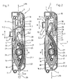
- the pinion 24 acts with the teeth of a circular arc curved Rack 27 together, in the embodiment of Figures 1 and 2, respectively an arcuate guide web 27.1 on each longitudinal side in the guides 17th both housing parts 2.1 and 2.2 is performed, in such a way that when turning of the pinion 24 in the direction of arrow B of Figure 1 by 180 °, the rack 27 the position shown in Figure 1, in which the local, the slider 11 closer lying end 27.2 at a distance from the intersection point 19 on the longitudinal side. 6 facing side of the median plane M and the other end 27.3 of the rack 27 at the end of 17.2, is moved to a position in which the Rack end 27.2 at the end of 17.1 and thus on the long side. 6 opposite side of the median plane M is located.
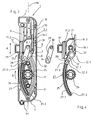
- each by means of an integrally formed on the rack 27 pivot pin 28 two Driving or control lever 29 hinged. Of these, each points to his other End of a pin 30 which engages in a driving opening 31 of the slider 11.
- the axes of the pivot pin 28 and the pin 30 are parallel to each other and parallel to the axis of rotation of the pinion 24.
- the entrainment opening 31 is located at the illustrated embodiment on the median plane M.
- the levers 29 are provided in pairs, d. H. congruent behind in the Figures 1 and 2 visible lever 29 is another lever 29, and that between the housing bottom 7 and the rack end 27.2 and the slide 11. Between the two levers 29 is a made of plastic pressure piece 32nd arranged, which with a convexly rounded end 32.1 in a arcuate, a bearing or a socket forming recess 33rd is received and with a convex shaped end 32.2 on the rounded rack end 27.2 supported. On both, one lever 29 each adjacent sides, the pressure piece 32 is provided with a guide groove 32.3, in the each a guide pin 34 of the adjacent lever 29 engages, so that the Pressure piece 32 when pivoting the lever 29 is carried properly.
- the actuating lever 26 of his in the Figure 1 lower position in the direction of arrow C pivoted upward to the Lower or close window or door sash, d. H. the operating lever 26 points at raised door or window sash from its pivot point (axis of the Pinion 24) down and closed and lowered window or Door wing upwards.
- FIG. 3 shows the actuating device 1 in a converted state.
- the end positions of the operating lever 26 are reversed, d. H. with lowered and closed door or window sash has the Operating lever 26 down and with open, raised door or Window wing upwards. This is achieved in that only the rack 27th is guided in the guides 16 and not in the guides 17.
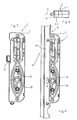
- Figures 10 and 11 show a further possible embodiment of a Actuating device 1a, which in turn of the two housing parts 2.1 and 2.2 formed housing 2, the rotatably mounted in this housing pinion 24, the arcuate curved rack 27 and a slider 11th corresponding slide 11a, which by turning the pinion 24 via the Rack 27 and two hinged in pairs with the rack end 27.2 and the slide 11a associated control lever in the housing longitudinal direction L to a predetermined stroke (double arrow A) can be moved, from the in 10, associated with the raised and opened wings Position in the position shown in the figure 1, the lowered and closed door or window sash corresponds.
- a predetermined stroke double arrow A
- the rack is 27th guided in the guides 17 of the two housing parts 2.1 and 2.2 slidably.
- the slider 11a is again against moving through outer, acting on the slide forces locked, u. a. as a result of that upon application of external forces, the slider 11a with a nose-like projection against the convex curved outer surface of the rack 27 in the area of the rack end 27.2 comes to rest and thus on the slider 11a exerted forces on the nose-like projection 38 on the rack 27th be transferred, as compressive forces, which is substantially radially or transversely to the curved guide 17 act and thus of this without moving the Rack 27 are received.
- the control levers 35 are each articulated at one end to the pivot pin 28 and provided at the other end with a pin 36 in a slot trained driving opening 37 of the slider 11a engages, the longer axis is parallel to the direction of movement of the slider.
- FIGS. 13-15 show, as a further embodiment, an actuating device 1b, which is obtained by simple conversion of the actuator 1a, namely in that, while maintaining the pinion 24, the rack 27 and the two Control lever 25, only the rack 27 is disposed in the guides 16 and the slider 11 a is replaced by a nearly identical slider 11 b.
- This has at its the rack 27 facing bottom the nose-like Projection 38 is not on, but is on this side with an inclined contact surface 39th Mistake.
- such forces acting on the slide in the sense of Pushing this slider back into the raised and opened state the door or window sash corresponding position, radially to the curved Guide 16 transmitted to the rack 27 and completely from the guide 16th added.
Landscapes
- Engineering & Computer Science (AREA)
- Mechanical Engineering (AREA)
- Transmission Devices (AREA)
- Window Of Vehicle (AREA)
- Power-Operated Mechanisms For Wings (AREA)
- Wing Frames And Configurations (AREA)
Description
- Fig. 1
- in Draufsicht ein Gehäuseteil einer neuerungsgemäßen Betätigungsvorrichtung (Hebegetriebe) für einen Treibstangenbeschlag einer Hebe-Schiebe-Tür oder eines Hebe-Schiebe-Fensters, wobei sich die Funktionselemente der Vorrichtung in einer dem angehobenen Zustand des Tür- oder Fensterflügels entsprechenden ersten Position befinden;
- Fig. 2
- eine Darstellung wie Figur 1, jedoch bei in einer dem abgesenkten Zustand des Tür- oder Fensterflügels entsprechenden Position der Funktionselemente;
- Fig. 3
- eine Darstellung wie Figur 1, jedoch für eine gegenüber der Figur 1 geänderte Ausgangs- und Endstellung eines Betätigungshebels;
- Fig. 4
- in Einzeldarstellung die Funktionselemente de Betätigungsvorrichtung der Figuren 1 - 3;
- Fig. 5 und 6
- jeweils in perspektivischer Einzeldarstellung die beiden im wesentlichen spiegelsymmetrisch zu einer Trennebene ausgebildeten schalenförmigen Gehäusehälften oder -teile der Betätigungsvorrichtung der Figuren 1 - 4;
- Fig. 7 und 8
- eine Seitenansicht sowie eine Draufsicht auf die Betätigungsvorrichtung der Figuren 1 - 4, bei geschlossenem Gehäuse;
- Fig. 9
- in Seitenansicht die an einer Stulpschiene eines Treibstangenbeschlages befestigte Betätigungsvorrichtung der Figuren 1 - 4;
- Fig. 10 und 11
- in Darstellungen ähnlich den Figuren 1 und 2 eine weitere mögliche Ausführungsform der neuerungsgemäßen Betätigungsvorrichtung;
- Fig. 12
- in perspektivischer Einzeldarstellung den Betätigungsschieber der Betätigungsvorrichtung der Figuren 10 und 11;
- Fig. 13 und 14
- in Darstellungen ähnlich den Figuren 10 und 11 die Betätigungsvorrichtung dieser Figuren in einem für geänderte Endstellungen des Betätigungshebels umgebauten Zustand;
- Fig. 15
- in perspektivischer Einzeldarstellung den etwas geänderten Betätigungsschieber zur Verwendung bei der Betätigungsvorrichtung der Figuren 13 und 14.
- 1, 1a, 1b
- Betätigungsvorrichtung
- 2
- Gehäuse der Betätigungsvorrichtung
- 2.1, 2.2
- Gehäuseteil
- 3, 4
- Schmalseiten
- 5, 6
- Längsseiten
- 7
- Gehäuseteilboden
- 8
- Gehäuseteilrand
- 9, 10
- Führung
- 11, 11a, 11b
- Schieber
- 11.1
- Schieberkörper
- 11.2, 11.3
- Führungsleiste
- 12
- Mitnehmer
- 13
- Stulpschiene
- 14
- Treibstangenbeschlag
- 15
- Treibstange
- 16, 17
- Führung
- 16.1,16.2
- Ende der Führung 16
- 17.1, 17.2
- Ende der Führung 17
- 18
- Vorsprung
- 19
- Schnittpunkt der Führungen 16 und 17
- 20
- Verstärkungsrippen
- 21
- zapfen- oder hülsenartiger Vorsprung
- 22
- Rasten
- 23
- Lageröffnung
- 24
- Ritzel
- 25
- Vierkantöffnung
- 26
- Betätigungshebel
- 27
- Zahnstange
- 27.1
- Führungssteg
- 27.2, 27.3
- Zahnstangenende
- 28
- Gelenkzapfen
- 29
- Steuerhebel
- 30
- Zapfen am Steuerhebel 29
- 31
- Mitnehmeröffnung
- 32
- Druckstück
- 32.1, 32.2
- Druckstückende
- 32.3
- Führungsnut
- 33
- Ausnehmung
- 34
- Führungszapfen
- 35
- Steuerhebel
- 36
- Zapfen
- 37
- Mitnahmeöffnung
- 38
- nasenartiger Vorsprung
- 39
- Anlagefläche
- A
- Hub des Schiebers 11, 11a oder 11b
- B
- Drehrichtung des Ritzels 24
- C
- Schwenkrichtung des Betätigungshebels 26
- M
- Mittelebene
- L
- Gehäuselängsachse
- TE
- Trennebene
Claims (11)
- Vorrichtung zum Betätigen eines Beschlages, beispielsweise zum Betätigen der Treibstange (15) eines Treibstangenbeschlages (14) für einen Fenster- und/oder Türflügel, mit einem mit dem Beschlag verbindbaren Kupplungs- oder Antriebselement (11, 11a, 11b), das zum Betätigen des Beschlages in einem Gehäuse (2) der Vorrichtung zumindest in einer ersten Achsrichtung (L) durch Drehen eines Getriebeelementes (24) mit einem äußeren Betätigungshebel (26) um einen vorgegebenen Hub (A) bewegbar und Bestandteil eines das Getriebeelement antriebsmäßig mit dem Kupplungs- oder Antriebselement (11, 11 a, 11 b) verbindenden und in dem Gehäuse (2) untergebrachten Getriebes ist, dadurch gekennzeichnet, daß das Getriebe als Zahnradgetriebe mit wenigstens einem Zahnrad oder Ritzel (24) sowie mit wenigstens einer mit diesem Zahnrad oder Ritzel (24) zusammenwirkenden und längs verschiebbar geführten Zahnstange (27) ausgebildet ist, und daß beidseitig von dem Zahnrad oder Ritzel (24) im Gehäuse (2) jeweils wenigstens eine Zahnstangenführung (16, 17) vorgesehen ist, und zwar zur wahlweisen Anordnung der Zahnstange (27) an der einen oder an der anderen Seite des Zahnrades oder Ritzels (24).
- Vorrichtung nach Anspruch 1, dadurch gekennzeichnet, daß das Zahnrad oder Ritzel (24) das mit dem Betätigungshebel (26) verbindbare Getriebeelement ist.
- Vorrichtung nach Anspruch 1 oder 2, dadurch gekennzeichnet, daß die Zahnstange (27) kreisbogenförmig gekrümmt ist und an ihrer bezogen auf diese Krümmung konkaven Seite eine mit dem wenigstens einen Zahnrad oder Ritzel (24) zusammenwirkende Verzahnung aufweist, und/oder daß die Führungen (16, 17) kreisbogenförmig gekrümmt ausgebildet sind.
- Vorrichtung nach einem der vorhergehenden Ansprüche, dadurch gekennzeichnet, daß die an den beiden Seiten des Zahnrades oder Ritzels (24) vorgesehenen Führungen (16, 17) derart ausgebildet sind, daß sich ein Zahnstangenabschnitt, beispielsweise ein Zahnstangenende (27.2), der bzw. das antriebsmäßig mit dem Kupplungs- oder Antriebselement (11, 11a, 11b) verbunden ist, beim Betätigen des Zahnrades oder Ritzels (24) auf einem Kreisbogen bewegt, und zwar bei einem vollen Hub des Kupplungs- oder Antriebselementes (11, 11a, 11b) zwischen einer ersten Position und einer zweiten Position, wobei beide Positionen zumindest in der Achsrichtung der Hubbewegung (A) des Kupplungs- oder Antriebselementes (11, 11a, 11b) gegeneinander versetzt sind,
wobei beispielsweise die Zahnstange (27) in der zweiten Position das Kupplungsoder Antriebselement (11, 11a, 11b) verriegelt. - Vorrichtung nach einem der vorhergehenden Ansprüche, dadurch gekennzeichnet, daß die Zahnstange (27) über wenigstens einen Hebel (29, 35) antriebsmäßig mit dem Kupplungs- oder Antriebselement (11, 11a, 11b) verbunden ist.
- Vorrichtung nach einem der vorhergehenden Ansprüche, dadurch gekennzeichnet, daß in der zweiten Position der Zahnstange (27) das Kupplungs- oder Antriebselement (11, 11a, 11b) zum Sperren seiner Bewegung über ein Druckstück (32) und/oder über eine am Kupplungs- oder Antriebselement gebildete Anlagefläche (38, 39) seitlich oder in einer Achsrichtung quer zur Bewegungsrichtung der Zahnstange (27) gegen diese anliegt.
- Vorrichtung nach einem der vorhergehenden Ansprüche, dadurch gekennzeichnet, daß der mit dem Kupplungs- oder Antriebselement (11, 11a, 11b) antriebsmäßig verbundene Abschnitt der Zahnstange (27) in der ersten und zweiten Position auf unterschiedlichen Seiten einer Achslinie (L) angeordnet ist, die parallel zur Achse der Hubbewegung (A) des Kupplungs- oder Antriebselementes (11, 11a, 11b) liegt und durch denjenigen Punkt am Kupplungs- oder Antriebselement (11, 11a, 11b) geht, an dem die antriebsmäßige Verbindung zwischen der Zahnstange und dem Kupplungs- oder Antriebselement angreift, beispielsweise der wenigstens eine Steuerhebel (29, 35) am Kupplungs- oder Antriebselement (11, 11a, 11b) angreift oder angelenkt ist.
- Vorrichtung nach einem der vorhergehenden Ansprüche, dadurch gekennzeichnet, daß das Gehäuse oder die das Gehäuse bildenden Gehäuseteile (2.1, 2.2) aus Kunststoff gefertigt sind, beispielsweise aus einem faserverstärkten Kunststoff.
- Vorrichtung nach einem der vorhergehenden Ansprüche, dadurch gekennzeichnet, daß die Führungen für das Kupplungs- oder Antriebselement (11, 11a, 11b) und/oder die Führungen (16, 17) für die Zahnstange (27) einstückig mit dem Gehäuse bzw. mit den Gehäuseteilen (2.1, 2.2) gefertigt sind und/oder von wenigstens einer Nut gebildet sind.
- Vorrichtung nach einem der vorhergehenden Ansprüche, dadurch gekennzeichnet, daß das Gehäuse (2) zweiteilig bestehend aus zwei Gehäuseteilen (2.1, 2.2) hergestellt ist, und daß die Gehäuseteile (2.1, 2.2) zumindest hinsichtlich der Führungen (9, 10; 16, 17) und/oder Lager (23) für die Elemente des Getriebes spiegelsymmetrisch zu einer Trennebene (TR) ausgebildet sind, an der die Gehäuseteile (2.1, 2.2) bei geschlossenem Gehäuse (2) aneinander anschließen.
- Vorrichtung nach einem der vorhergehenden Ansprüche, dadurch gekennzeichnet, daß das Kupplungs- oder Antriebselement ein im Gehäuse (2) verschiebbarer Betätigungsschieber (11, 11a, 11b) ist.
Applications Claiming Priority (2)
| Application Number | Priority Date | Filing Date | Title |
|---|---|---|---|
| DE20212724U DE20212724U1 (de) | 2002-08-14 | 2002-08-14 | Betätigungsvorrichtung zur Verwendung bei einem Beschlag für eine Hebe-Schiebe-Tür oder ein Hebe-Schiebe-Fenster |
| DE20212724U | 2002-08-14 |
Publications (2)
| Publication Number | Publication Date |
|---|---|
| EP1391575A1 EP1391575A1 (de) | 2004-02-25 |
| EP1391575B1 true EP1391575B1 (de) | 2005-01-26 |
Family
ID=7974218
Family Applications (1)
| Application Number | Title | Priority Date | Filing Date |
|---|---|---|---|
| EP03012468A Expired - Lifetime EP1391575B1 (de) | 2002-08-14 | 2003-05-31 | Betätigungsvorrichtung zur Verwendung bei einem Beschlag für eine Hebe-Schiebe-Tür oder ein Hebe-Schiebe-Fenster |
Country Status (4)
| Country | Link |
|---|---|
| EP (1) | EP1391575B1 (de) |
| AT (1) | ATE288012T1 (de) |
| DE (2) | DE20212724U1 (de) |
| ES (1) | ES2236644T3 (de) |
Families Citing this family (1)
| Publication number | Priority date | Publication date | Assignee | Title |
|---|---|---|---|---|
| CN113425127B (zh) * | 2021-08-11 | 2022-09-06 | 杭州拓凡展示工程有限公司 | 一种多功能展柜 |
Family Cites Families (5)
| Publication number | Priority date | Publication date | Assignee | Title |
|---|---|---|---|---|
| FR1591102A (de) * | 1968-10-02 | 1970-04-27 | ||
| DE2824206A1 (de) * | 1978-06-02 | 1979-12-06 | Gretsch Unitas Gmbh | Schiebe-kipp-tuer oder -fenster |
| DE4402479C1 (de) * | 1994-01-28 | 1995-04-13 | Steinbach & Vollmann | Verschluß |
| EP1216335B1 (de) * | 1999-10-01 | 2004-10-20 | Siegenia-Aubi Kg | Zwischengetriebe für fenster-oder türbeschlag |
| DE20116796U1 (de) * | 2001-09-27 | 2002-04-25 | Gretsch-Unitas GmbH Baubeschläge, 71254 Ditzingen | Betätigungsgetriebe, insbesondere Schloss für einen Treibstangenbeschlag sowie Treibstangenbeschlag mit einem solchen Betätigungsgetriebe |
-
2002
- 2002-08-14 DE DE20212724U patent/DE20212724U1/de not_active Expired - Lifetime
-
2003
- 2003-05-31 EP EP03012468A patent/EP1391575B1/de not_active Expired - Lifetime
- 2003-05-31 ES ES03012468T patent/ES2236644T3/es not_active Expired - Lifetime
- 2003-05-31 AT AT03012468T patent/ATE288012T1/de not_active IP Right Cessation
- 2003-05-31 DE DE50300277T patent/DE50300277D1/de not_active Expired - Lifetime
Also Published As
| Publication number | Publication date |
|---|---|
| DE20212724U1 (de) | 2002-11-14 |
| DE50300277D1 (de) | 2005-03-03 |
| EP1391575A1 (de) | 2004-02-25 |
| ES2236644T3 (es) | 2005-07-16 |
| ATE288012T1 (de) | 2005-02-15 |
Similar Documents
| Publication | Publication Date | Title |
|---|---|---|
| DE2920581C2 (de) | Zusatzverriegelung, insbesondere Mittelverriegelung, für Fenster, Türen od.dgl. | |
| EP0440986B1 (de) | Treibstangengetriebe | |
| EP0440987B2 (de) | Treibstangengetriebe | |
| DE3631516C2 (de) | ||
| EP3985216B1 (de) | Flügelanordnung | |
| EP0763641A1 (de) | Betätigungsvorrichtung | |
| DE19521539A1 (de) | Drehlager, insbesondere Scherenlager eines Drehbeschlags oder Dreh-Kippbeschlags für Fenster, Türen oder dergleichen | |
| EP1298269B1 (de) | Betätigungsgetriebe, insbesondere Schloss für einen Treibstangenbeschlag sowie Treibstangenbeschlag mit einem solchen Betätigungsgetriebe | |
| EP1223287B1 (de) | Montagefreundliche Scherenanordnung mit Zusatzfunktion | |
| DE102009050875A1 (de) | Vorrichtung zum Öffnen und Schließen von Fenstern an Wohnwagen, Wohnmobilen und dergleichen | |
| DE9001279U1 (de) | Treibstangengetriebe | |
| EP4095339B1 (de) | Stulphebelgetriebe | |
| EP0367842B1 (de) | Handhebelgetriebe zum Aufschrauben auf den Flügelrahmen von Fenstern, Türen oder dergleichen | |
| DE69807608T2 (de) | Schliessvorrichtung, insbesondere Einsteckschloss mit einer Falle, für eine Fenstertür oder dergleichen | |
| AT397976B (de) | Türschloss mit längs der längeren seite der tür angeordneten mit sperrbolzen versehenen riegelstangen | |
| EP3744929B1 (de) | Stangenverschluss | |
| EP1288418B1 (de) | Beschlagseinheit für ein Kipp- oder Drehkippfenster | |
| EP2218849A2 (de) | Handhabe für Dreh-Kipp-Fenster und Dreh-Kipp-Türen | |
| EP1391575A1 (de) | Betätigungsvorrichtung zur Verwendung bei einem Beschlag für eine Hebe-Schiebe-Tür oder ein Hebe-Schiebe-Fenster | |
| EP4174266A1 (de) | Flügelanordnung | |
| EP0606877B1 (de) | Beschlag für ein eine Falle und einen Riegel aufweisendes Schloss | |
| EP1862631A2 (de) | Antriebsanordnung zur motorischen Verstellung eines Verschlußelements eines Kraftfahrzeugs | |
| DE69703015T2 (de) | Treibstangenbremsevorrichtung und Schiebeflügel mit einer solchen Vorrichtung | |
| DE102024203222B3 (de) | Beschlaganordnung für ein Fenster, eine Tür oder dergleichen zur Betätigung einer Feststellbremse | |
| EP2295678B1 (de) | Beschlag für ein Fenster, eine Tür oder dergleichen sowie Fenster, Tür oder dergleichen mit einem derartigen Beschlag |
Legal Events
| Date | Code | Title | Description |
|---|---|---|---|
| PUAI | Public reference made under article 153(3) epc to a published international application that has entered the european phase |
Free format text: ORIGINAL CODE: 0009012 |
|
| AK | Designated contracting states |
Kind code of ref document: A1 Designated state(s): AT BE BG CH CY CZ DE DK EE ES FI FR GB GR HU IE IT LI LU MC NL PT RO SE SI SK TR |
|
| AX | Request for extension of the european patent |
Extension state: AL LT LV MK |
|
| 17P | Request for examination filed |
Effective date: 20040405 |
|
| GRAP | Despatch of communication of intention to grant a patent |
Free format text: ORIGINAL CODE: EPIDOSNIGR1 |
|
| GRAS | Grant fee paid |
Free format text: ORIGINAL CODE: EPIDOSNIGR3 |
|
| AKX | Designation fees paid |
Designated state(s): AT BE BG CH CY CZ DE DK EE ES FI FR GB GR HU IE IT LI LU MC NL PT RO SE SI SK TR |
|
| GRAA | (expected) grant |
Free format text: ORIGINAL CODE: 0009210 |
|
| AK | Designated contracting states |
Kind code of ref document: B1 Designated state(s): AT BE BG CH CY CZ DE DK EE ES FI FR GB GR HU IE IT LI LU MC NL PT RO SE SI SK TR |
|
| PG25 | Lapsed in a contracting state [announced via postgrant information from national office to epo] |
Ref country code: RO Free format text: LAPSE BECAUSE OF FAILURE TO SUBMIT A TRANSLATION OF THE DESCRIPTION OR TO PAY THE FEE WITHIN THE PRESCRIBED TIME-LIMIT Effective date: 20050126 Ref country code: BG Free format text: LAPSE BECAUSE OF FAILURE TO SUBMIT A TRANSLATION OF THE DESCRIPTION OR TO PAY THE FEE WITHIN THE PRESCRIBED TIME-LIMIT Effective date: 20050126 Ref country code: EE Free format text: LAPSE BECAUSE OF FAILURE TO SUBMIT A TRANSLATION OF THE DESCRIPTION OR TO PAY THE FEE WITHIN THE PRESCRIBED TIME-LIMIT Effective date: 20050126 Ref country code: SI Free format text: LAPSE BECAUSE OF FAILURE TO SUBMIT A TRANSLATION OF THE DESCRIPTION OR TO PAY THE FEE WITHIN THE PRESCRIBED TIME-LIMIT Effective date: 20050126 Ref country code: FI Free format text: LAPSE BECAUSE OF FAILURE TO SUBMIT A TRANSLATION OF THE DESCRIPTION OR TO PAY THE FEE WITHIN THE PRESCRIBED TIME-LIMIT Effective date: 20050126 Ref country code: GB Free format text: LAPSE BECAUSE OF FAILURE TO SUBMIT A TRANSLATION OF THE DESCRIPTION OR TO PAY THE FEE WITHIN THE PRESCRIBED TIME-LIMIT Effective date: 20050126 Ref country code: SK Free format text: LAPSE BECAUSE OF FAILURE TO SUBMIT A TRANSLATION OF THE DESCRIPTION OR TO PAY THE FEE WITHIN THE PRESCRIBED TIME-LIMIT Effective date: 20050126 Ref country code: CZ Free format text: LAPSE BECAUSE OF FAILURE TO SUBMIT A TRANSLATION OF THE DESCRIPTION OR TO PAY THE FEE WITHIN THE PRESCRIBED TIME-LIMIT Effective date: 20050126 Ref country code: IE Free format text: LAPSE BECAUSE OF FAILURE TO SUBMIT A TRANSLATION OF THE DESCRIPTION OR TO PAY THE FEE WITHIN THE PRESCRIBED TIME-LIMIT Effective date: 20050126 |
|
| REG | Reference to a national code |
Ref country code: GB Ref legal event code: FG4D Free format text: NOT ENGLISH |
|
| REG | Reference to a national code |
Ref country code: CH Ref legal event code: EP |
|
| REG | Reference to a national code |
Ref country code: IE Ref legal event code: FG4D Free format text: GERMAN |
|
| REF | Corresponds to: |
Ref document number: 50300277 Country of ref document: DE Date of ref document: 20050303 Kind code of ref document: P |
|
| REG | Reference to a national code |
Ref country code: GR Ref legal event code: EP Ref document number: 20050400770 Country of ref document: GR |
|
| PG25 | Lapsed in a contracting state [announced via postgrant information from national office to epo] |
Ref country code: SE Free format text: LAPSE BECAUSE OF FAILURE TO SUBMIT A TRANSLATION OF THE DESCRIPTION OR TO PAY THE FEE WITHIN THE PRESCRIBED TIME-LIMIT Effective date: 20050426 Ref country code: DK Free format text: LAPSE BECAUSE OF FAILURE TO SUBMIT A TRANSLATION OF THE DESCRIPTION OR TO PAY THE FEE WITHIN THE PRESCRIBED TIME-LIMIT Effective date: 20050426 |
|
| PG25 | Lapsed in a contracting state [announced via postgrant information from national office to epo] |
Ref country code: HU Free format text: LAPSE BECAUSE OF FAILURE TO SUBMIT A TRANSLATION OF THE DESCRIPTION OR TO PAY THE FEE WITHIN THE PRESCRIBED TIME-LIMIT Effective date: 20050427 |
|
| PG25 | Lapsed in a contracting state [announced via postgrant information from national office to epo] |
Ref country code: MC Free format text: LAPSE BECAUSE OF NON-PAYMENT OF DUE FEES Effective date: 20050531 Ref country code: CY Free format text: LAPSE BECAUSE OF FAILURE TO SUBMIT A TRANSLATION OF THE DESCRIPTION OR TO PAY THE FEE WITHIN THE PRESCRIBED TIME-LIMIT Effective date: 20050531 Ref country code: LU Free format text: LAPSE BECAUSE OF NON-PAYMENT OF DUE FEES Effective date: 20050531 |
|
| REG | Reference to a national code |
Ref country code: ES Ref legal event code: FG2A Ref document number: 2236644 Country of ref document: ES Kind code of ref document: T3 |
|
| GBV | Gb: ep patent (uk) treated as always having been void in accordance with gb section 77(7)/1977 [no translation filed] |
Effective date: 20050126 |
|
| REG | Reference to a national code |
Ref country code: IE Ref legal event code: FD4D |
|
| PLBE | No opposition filed within time limit |
Free format text: ORIGINAL CODE: 0009261 |
|
| STAA | Information on the status of an ep patent application or granted ep patent |
Free format text: STATUS: NO OPPOSITION FILED WITHIN TIME LIMIT |
|
| ET | Fr: translation filed | ||
| 26N | No opposition filed |
Effective date: 20051027 |
|
| PG25 | Lapsed in a contracting state [announced via postgrant information from national office to epo] |
Ref country code: PT Free format text: LAPSE BECAUSE OF NON-PAYMENT OF DUE FEES Effective date: 20050626 |
|
| REG | Reference to a national code |
Ref country code: CH Ref legal event code: PL |
|
| PG25 | Lapsed in a contracting state [announced via postgrant information from national office to epo] |
Ref country code: LI Free format text: LAPSE BECAUSE OF NON-PAYMENT OF DUE FEES Effective date: 20070531 Ref country code: CH Free format text: LAPSE BECAUSE OF NON-PAYMENT OF DUE FEES Effective date: 20070531 |
|
| PGFP | Annual fee paid to national office [announced via postgrant information from national office to epo] |
Ref country code: ES Payment date: 20080529 Year of fee payment: 6 |
|
| PGFP | Annual fee paid to national office [announced via postgrant information from national office to epo] |
Ref country code: AT Payment date: 20080515 Year of fee payment: 6 |
|
| PGFP | Annual fee paid to national office [announced via postgrant information from national office to epo] |
Ref country code: BE Payment date: 20080620 Year of fee payment: 6 Ref country code: IT Payment date: 20080522 Year of fee payment: 6 Ref country code: TR Payment date: 20080424 Year of fee payment: 6 |
|
| PGFP | Annual fee paid to national office [announced via postgrant information from national office to epo] |
Ref country code: NL Payment date: 20080515 Year of fee payment: 6 |
|
| PGFP | Annual fee paid to national office [announced via postgrant information from national office to epo] |
Ref country code: GR Payment date: 20080514 Year of fee payment: 6 |
|
| BERE | Be: lapsed |
Owner name: *GRETSCH-UNITAS G.M.B.H. Effective date: 20090531 |
|
| PG25 | Lapsed in a contracting state [announced via postgrant information from national office to epo] |
Ref country code: AT Free format text: LAPSE BECAUSE OF NON-PAYMENT OF DUE FEES Effective date: 20090531 |
|
| NLV4 | Nl: lapsed or anulled due to non-payment of the annual fee |
Effective date: 20091201 |
|
| PG25 | Lapsed in a contracting state [announced via postgrant information from national office to epo] |
Ref country code: NL Free format text: LAPSE BECAUSE OF NON-PAYMENT OF DUE FEES Effective date: 20091201 |
|
| REG | Reference to a national code |
Ref country code: FR Ref legal event code: ST Effective date: 20100129 |
|
| PG25 | Lapsed in a contracting state [announced via postgrant information from national office to epo] |
Ref country code: FR Free format text: LAPSE BECAUSE OF NON-PAYMENT OF DUE FEES Effective date: 20090602 |
|
| PGFP | Annual fee paid to national office [announced via postgrant information from national office to epo] |
Ref country code: FR Payment date: 20080526 Year of fee payment: 6 |
|
| PG25 | Lapsed in a contracting state [announced via postgrant information from national office to epo] |
Ref country code: BE Free format text: LAPSE BECAUSE OF NON-PAYMENT OF DUE FEES Effective date: 20090531 Ref country code: GR Free format text: LAPSE BECAUSE OF NON-PAYMENT OF DUE FEES Effective date: 20091202 |
|
| REG | Reference to a national code |
Ref country code: ES Ref legal event code: FD2A Effective date: 20090601 |
|
| PG25 | Lapsed in a contracting state [announced via postgrant information from national office to epo] |
Ref country code: ES Free format text: LAPSE BECAUSE OF NON-PAYMENT OF DUE FEES Effective date: 20090601 |
|
| PG25 | Lapsed in a contracting state [announced via postgrant information from national office to epo] |
Ref country code: IT Free format text: LAPSE BECAUSE OF NON-PAYMENT OF DUE FEES Effective date: 20090531 |
|
| PG25 | Lapsed in a contracting state [announced via postgrant information from national office to epo] |
Ref country code: TR Free format text: LAPSE BECAUSE OF NON-PAYMENT OF DUE FEES Effective date: 20090531 |
|
| PGFP | Annual fee paid to national office [announced via postgrant information from national office to epo] |
Ref country code: DE Payment date: 20170523 Year of fee payment: 15 |
|
| REG | Reference to a national code |
Ref country code: DE Ref legal event code: R119 Ref document number: 50300277 Country of ref document: DE |
|
| PG25 | Lapsed in a contracting state [announced via postgrant information from national office to epo] |
Ref country code: DE Free format text: LAPSE BECAUSE OF NON-PAYMENT OF DUE FEES Effective date: 20181201 |