EP1389771B1 - Système et procédé de traitement d'images numériques permettant de combiner une operation de démosaiquage et une correction de mauvais pixels - Google Patents
Système et procédé de traitement d'images numériques permettant de combiner une operation de démosaiquage et une correction de mauvais pixels Download PDFInfo
- Publication number
- EP1389771B1 EP1389771B1 EP03009920A EP03009920A EP1389771B1 EP 1389771 B1 EP1389771 B1 EP 1389771B1 EP 03009920 A EP03009920 A EP 03009920A EP 03009920 A EP03009920 A EP 03009920A EP 1389771 B1 EP1389771 B1 EP 1389771B1
- Authority
- EP
- European Patent Office
- Prior art keywords
- sensor values
- values
- sensor
- pixels
- pixel
- Prior art date
- Legal status (The legal status is an assumption and is not a legal conclusion. Google has not performed a legal analysis and makes no representation as to the accuracy of the status listed.)
- Expired - Fee Related
Links
- 238000000034 method Methods 0.000 title claims abstract description 51
- 238000012937 correction Methods 0.000 title abstract description 14
- 230000002950 deficient Effects 0.000 claims abstract description 78
- 230000008569 process Effects 0.000 abstract description 19
- 238000012545 processing Methods 0.000 description 9
- 238000001514 detection method Methods 0.000 description 6
- 239000003086 colorant Substances 0.000 description 4
- 238000001914 filtration Methods 0.000 description 4
- 238000004519 manufacturing process Methods 0.000 description 4
- 230000010076 replication Effects 0.000 description 4
- 238000012360 testing method Methods 0.000 description 4
- 230000008901 benefit Effects 0.000 description 3
- 238000010586 diagram Methods 0.000 description 3
- 230000009467 reduction Effects 0.000 description 3
- 230000006835 compression Effects 0.000 description 2
- 238000007906 compression Methods 0.000 description 2
- 238000011109 contamination Methods 0.000 description 2
- 238000003384 imaging method Methods 0.000 description 2
- 239000012535 impurity Substances 0.000 description 2
- 238000012552 review Methods 0.000 description 2
- 241001428800 Cell fusing agent virus Species 0.000 description 1
- 241000233805 Phoenix Species 0.000 description 1
- 238000013459 approach Methods 0.000 description 1
- 238000004364 calculation method Methods 0.000 description 1
- 238000006243 chemical reaction Methods 0.000 description 1
- 230000007547 defect Effects 0.000 description 1
- 238000002059 diagnostic imaging Methods 0.000 description 1
- 230000006870 function Effects 0.000 description 1
- 238000005286 illumination Methods 0.000 description 1
- 208000036971 interstitial lung disease 2 Diseases 0.000 description 1
- 239000011159 matrix material Substances 0.000 description 1
- 229910044991 metal oxide Inorganic materials 0.000 description 1
- 150000004706 metal oxides Chemical class 0.000 description 1
- 230000004044 response Effects 0.000 description 1
- 239000004065 semiconductor Substances 0.000 description 1
Images


Classifications
-
- G—PHYSICS
- G06—COMPUTING; CALCULATING OR COUNTING
- G06T—IMAGE DATA PROCESSING OR GENERATION, IN GENERAL
- G06T3/00—Geometric image transformation in the plane of the image
- G06T3/40—Scaling the whole image or part thereof
- G06T3/4015—Demosaicing, e.g. colour filter array [CFA], Bayer pattern
-
- G—PHYSICS
- G06—COMPUTING; CALCULATING OR COUNTING
- G06T—IMAGE DATA PROCESSING OR GENERATION, IN GENERAL
- G06T5/00—Image enhancement or restoration
- G06T5/20—Image enhancement or restoration by the use of local operators
-
- G06T5/77—
-
- G—PHYSICS
- G06—COMPUTING; CALCULATING OR COUNTING
- G06T—IMAGE DATA PROCESSING OR GENERATION, IN GENERAL
- G06T7/00—Image analysis
- G06T7/0002—Inspection of images, e.g. flaw detection
- G06T7/0004—Industrial image inspection
-
- H—ELECTRICITY
- H04—ELECTRIC COMMUNICATION TECHNIQUE
- H04N—PICTORIAL COMMUNICATION, e.g. TELEVISION
- H04N23/00—Cameras or camera modules comprising electronic image sensors; Control thereof
- H04N23/10—Cameras or camera modules comprising electronic image sensors; Control thereof for generating image signals from different wavelengths
- H04N23/12—Cameras or camera modules comprising electronic image sensors; Control thereof for generating image signals from different wavelengths with one sensor only
-
- H—ELECTRICITY
- H04—ELECTRIC COMMUNICATION TECHNIQUE
- H04N—PICTORIAL COMMUNICATION, e.g. TELEVISION
- H04N23/00—Cameras or camera modules comprising electronic image sensors; Control thereof
- H04N23/80—Camera processing pipelines; Components thereof
- H04N23/84—Camera processing pipelines; Components thereof for processing colour signals
- H04N23/843—Demosaicing, e.g. interpolating colour pixel values
-
- H—ELECTRICITY
- H04—ELECTRIC COMMUNICATION TECHNIQUE
- H04N—PICTORIAL COMMUNICATION, e.g. TELEVISION
- H04N25/00—Circuitry of solid-state image sensors [SSIS]; Control thereof
- H04N25/60—Noise processing, e.g. detecting, correcting, reducing or removing noise
- H04N25/68—Noise processing, e.g. detecting, correcting, reducing or removing noise applied to defects
-
- G—PHYSICS
- G06—COMPUTING; CALCULATING OR COUNTING
- G06T—IMAGE DATA PROCESSING OR GENERATION, IN GENERAL
- G06T2207/00—Indexing scheme for image analysis or image enhancement
- G06T2207/10—Image acquisition modality
- G06T2207/10024—Color image
Definitions
- the present invention relates generally to digital color image sensors, and specifically to image processing of sensor values.
- CCDs Charge Coupled Devices
- CMOS - APS Complimentary Metal Oxide Semiconductor - Active Pixel Sensors
- Both types of sensors typically contain an array of photo-detectors, arranged in a pattern, that sample color within an image. Each photo-detector corresponds to a pixel of an image and measures the intensity of light of the pixel within one or more ranges of wavelengths, corresponding to one or more perceived colors.
- both types of sensors may include a color filter array (CFA), such as the CFA described in U.S. Patent No. 3,971,065 to Bayer (hereinafter referred to as Bayer).
- CFA color filter array
- Bayer the CFA described in U.S. Patent No. 3,971,065 to Bayer
- each pixel sees only one wavelength range, corresponding to the perceived color red, green or blue.
- demosaicing There are a number of demosaicing methods known in the art today. By way of example, but not limitation, various demosaicing methods have included pixel replication, bilinear interpolation and median interpolation.
- bad pixel correction The process of detecting and correcting defective pixels is referred to as bad pixel correction (BPC).
- BPC bad pixel correction
- the Maynants & Diercickx BPC method does not compare sensor values that are spatially adjacent to the current pixel, and therefore has the drawback of erasing local ridges in the image, where sensor values peak or recess.
- the Maynants & Diercickx BPC method does not compare sensor values vertically, and therefore has the additional drawback of erasing fine vertical lines.
- Tan & Acharya Another BPC method for color image sensors proposed by Tan & Acharya in "A robust sequential approach for the detection of defective pixels in an image sensor" Proceedings of the 1999 International Conference on Acoustics, Speech and Signal Processing, Phoenix, Arizona, March 15-19, 1999, p. 2239-2242 , builds a bad pixel map by accumulating the result of bad pixel detection over a sequence of images based on a minimum difference between a given pixel and its immediate neighbors of the same color.
- the Tan & Acharya method requires the storage of the bad pixel map in non-volatile memory. Incorporating non-volatile memory into an image sensor or an image processor chip is a significant expense.
- the Tan & Acharya method also does not compare spatially adjacent sensor values when creating the bad pixel map.
- EP 1 003 332 A2 describes a method and apparatus for correcting defective pixel values based on the values of a plurality of neighboring pixels.
- the filtering of each pixel value uses the value of the current pixel as part of a dataset including the values of neighboring pixels.
- a first filtering stage the current pixel is compared with highest and lowest ranked pixel values in its neighborhood; if the value of the current pixel is greater than the highest ranked value, this highest ranked value is replacing the current pixel. If the value of the current pixel is lower than the lowest ranked value, the lowest ranked value is replacing the current pixel.
- This first filtering stage acts as a general noise reduction filter.
- the median value of the pixels neighboring the current pixel is calculated. The median value used is the mean value of the two middle ranked pixel values.
- the values of the current pixel and of the neighboring pixels is sorted into rank order and the current pixel value is modified on the basis of its place in said rank order.
- bad pixel correction that effectively and accurately detects and corrects defective pixels using spatially adjacent sensor values to identify defective pixels near edges and in regions of texture.
- bad pixel correction (BPC) and demosaicing have traditionally been performed in two separate stages, either in software or in a digital circuit implemented in hardware. Each stage adds to the expense and complexity of processing sensor values for final output on a display device. Therefore, what is further needed is a method that combines an accurate BPC algorithm with demosaicing in a single stage.
- the present invention provides a digital image system according to claim 1 and a method for correcting sensor values generated by pixels according to claim 5.
- Embodiments of the present invention provide a digital image system and method for detecting and correcting defective pixels by interpolating sensor values of pixels adjacent to a current pixel being examined and comparing the interpolated sensor values to the sensor value of the current pixel to determine whether the current pixel is defective. Further embodiments of the present invention enable the combination of bad pixel correction and demosaicing in a single stage by using the interpolated values determined for detection of defective pixels for demosaicing.
- the bad pixel correction algorithm detects defective pixels using interpolated values in the same color plane as the current pixel being examined for the pixels immediately spatially adjacent to the current pixel.
- the interpolated values are calculated using a median interpolation technique to ensure that any defective sensor values remain isolated. If the sensor value of the current pixel being examined is above the maximum of the sensor values (actual and/or interpolated) of the immediately spatially adjacent neighbors or below the minimum of the sensor values of the immediately spatially adjacent neighbors by more than a configurable threshold amount, the current pixel is determined to be defective. For each defective pixel detected, the sensor value of the defective pixel is replaced using an estimated sensor value calculated from the actual sensor values of neighboring pixels in the same color plane and/or the interpolated values of immediately spatially adjacent neighboring pixels.
- the previously interpolated values used for the detection of defective pixels can be applied during demosaicing.
- these interpolated values can be used as the interpolated values for demosaicing purposes.
- the two processes can be performed in a single stage.
- using interpolated values during BPC provides the additional advantage of identifying defective pixels near edges and in regions of texture, since both vertical and horizontal pixel neighbors nearest to the pixel being examined are used in the calculation of the interpolated values.
- the invention provides embodiments with other features and advantages in addition to or in lieu of those discussed above. Many of these features and advantages are apparent from the description below with reference to the following drawings.
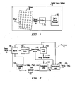
- FIG. 1 shows a digital image system 10 implementing a bad pixel correction (BPC) algorithm, that can be combined with a demosaicing algorithm, in accordance with the present invention.
- the digital image system 10 can be any digital imaging device, such as a digital camera, video camera, medical imaging device, etc.
- the digital image system 10 can also be a computer system, such as a personal computer or server, having a memory therein for storing image data.
- the algorithm can be within a digital imaging device or a part of an image processing software running on a personal computer or server.
- the digital image system 10 may include a digital image sensor 20, such as a CMOS sensor chip or a CCD sensor chip, which includes a two-dimensional array of pixels 25 arranged in rows and columns. It should be understood that if the digital image system 10 is a computer system, the digital image sensor 20 is not included within the digital image system, but rather provides sensor values to the digital image system 10.
- the digital image sensor 20 may be covered by a color filter array (CFA), such that each pixel 25 senses only one color.
- the CFA can be the popular Bayer CFA, in which chrominance colors (red and blue) are interspersed amongst a checkerboard pattern of luminance colors (green).
- the digital image sensor 20 provides raw sensor values 30 containing the original red, blue and green pixel values to a digital signal processor 40, which applies the BPC (and demosaicing) algorithm of the present invention to the sensor values 30 in order to detect and correct defective pixels and interpolate sensor values to produce a complete image.
- the sensor values 30 are provided to the digital signal processor 40 blocks at a time. Thus, the sensor values 30 are stored in a buffer 50 until the requisite number of sensor values 30 is present to begin processing.
- the number of sensor values 30 needed to begin processing depends on the type of processing.
- the sensor values 30 are typically read off the sensor 20 one row at a time.
- at least five rows of sensor values 30 are stored within the buffer 50.
- the rows include the current row including the sensor value of the current pixel being examined and the two rows directly above and directly below the current row to interpolate sensor values for immediately spatially adjacent neighbors to the current pixel.
- the immediately spatially adjacent neighbors are those pixels that are directly adjacent to a particular pixel, such that no other pixels are in between the particular pixel and one of the immediately spatially adjacent neighboring pixels.
- one or more images may be stored in the buffer 50 at a time.
- the interpolated (demosaiced) color planes can be used in subsequent processing (not shown).
- the interpolated color planes can be compressed using a compression method (not shown), such as the JPEG standard, prior to being output to an output device (not shown), such as a video screen, computer screen or printer.
- the digital signal processor 40 detects and corrects defective pixels 25 for sensor values in each image stored in the buffer 50 according to logic associated with the BPC algorithm.
- the BPC processor 40 takes as input the raw sensor values 30 provided by the buffer 50.
- the raw sensor values 30 include the sensor value 35 of the current pixel (Value 1 Pixel x ) and sensor values 30 of neighboring pixels in the current row of the current pixel and/or the row(s) directly above or directly below the current row.
- Interpolation logic 100 within the BPC processor 40 calculates interpolated sensor values 105 for the immediately spatially adjacent neighboring pixels to the current pixel from the raw sensor values 30 of neighboring pixels surrounding the current pixel in the same color plane as the current pixel.
- the term "logic” refers to the hardware, software and/or firmware for performing the stated function.
- Interpolation logic 100 uses a median interpolation technique to ensure that any defective sensor values remain isolated.
- the maximum and minimum sensor values among B 1 , B 2 , B 3 and B 4 are filtered out and the average of the remaining two sensor values is used as the interpolated blue value for the red pixel location (R 1 ).
- any defective sensor values can be filtered out to avoid skewing the interpolated values used for bad pixel detection, and ultimately, demosaicing of the image.
- the interpolated values 105 and in some embodiments, the raw sensor values 30 (as discussed below in connection with FIGs. 4-7), are provided to range logic 110 to determine a range of sensor values 115 in the same color plane as the current pixel from the immediately spatially adjacent neighboring pixels.
- the range of sensor values 115 can include a maximum sensor value and minimum sensor value from the interpolated values for the immediately spatially adjacent pixels.
- the raw sensor values 30 can further be provided to threshold logic 120 to compute a threshold amount 125.
- the threshold amount 125 can be variable depending on the light conditions of the image. In low light conditions, the sensor values are low and the signal to noise ratio is low, thus requiring a lower threshold amount 125 for determining whether a pixel is defective. By contrast, in normal or bright light conditions, the sensor values are high and the signal to noise ratio is high, thereby enabling a higher threshold amount 125 to be set for determining whether a pixel is defective.
- the light conditions are measured by the auto exposure system. For example, in low light conditions, the auto exposure opens the shutter for a longer period of time than in normal or bright light conditions.
- the threshold amount 125 can be set based on the auto exposure system of the camera. Additionally, by lowering the threshold amount 125 in low light conditions, the BPC process can further serve to improve noise levels in low light images. Thus, in some embodiments, the threshold amount 125 can be set during the manufacturing process, by an operator of the digital image system or using a table of values for the threshold amount based on light conditions, etc. In other embodiments, the threshold amount 125 can be fixed or pre-configured based on the sensor and CFA being used.
- the threshold amount 125, the range of values 115 and the sensor value 35a of the current pixel are provided to comparison logic 130 to determine whether the current pixel is a defective pixel.
- Comparison logic 130 compares the sensor value 35a of the current pixel to the range of values 115 and if the sensor value 35a of the current pixel is greater than the maximum of the range of sensor values 115 or less than the minimum of the range of sensor values 115 by more than the threshold amount 125, the current pixel is determined to be a defective pixel.
- replacement logic 140 calculates a replacement sensor value 35b (e.g., Value 2 Pixel x ) using the sensor values of the neighboring pixels and replaces the sensor value 35a of the defective pixel with the replacement value sensor 35b.
- the replacement sensor value 35b can be the median of the interpolated values 105 of the pixels immediately spatially adjacent to the current pixel.
- the replacement sensor value 35b can be the median of all immediately spatially adjacent sensor values, including both actual sensor values 30 and interpolated sensor values 105.
- other replacement sensor values 35b can be used, such as a bilinear value or pixel replication value.
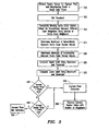
- a threshold amount can be set (step 305) to reduce the number of false bad pixel detections.
- the threshold amount can be either pre-set based on the sensor, operator preference or CFA or variable depending on the light conditions of the image.
- the sensor values in the same color plane as the current pixel are interpolated for immediately spatially adjacent pixels in different color planes using a median interpolation technique (step 310) to ensure that any defective sensor values remain isolated. From these interpolated values, and any immediately spatially adjacent raw (actual) sensor values in the same color plane, a maximum estimate (step 315) and a minimum estimate (step 320) for the sensor value of the current pixel are determined. The threshold amount is added to the maximum estimate to compute an upper limit (step 325) and subtracted from the lower estimate to compute a lower limit (step 330).
- the current pixel is determined to be defective (step 345), and the sensor value of the current pixel is replaced with a replacement sensor value estimated from the immediately spatially adjacent neighboring pixels (step 350). However, if the sensor value is neither above the upper limit nor below the lower limit, the current pixel is not defective (step 355) and no changes are made to the sensor value of the current pixel.
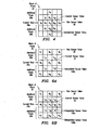
- FIG. 4 shows an example of a 5x5 block of pixels 25 illustrating sample raw green sensor values and interpolated green sensor values produced in accordance with embodiments of the BPC algorithm of the present invention.
- the sensor value 35 of the current pixel under review is labeled G 5
- the raw sensor values 30 obtained from pixels that are the same color as the current pixel are labeled "G n "
- the interpolated sensor values 105 obtained from neighboring raw sensor values are labeled "g n ".
- Sensor values are not shown for those pixels that are not used in the determination of whether the current pixel is defective.
- both the current row 28a of sensor values 30 that includes the current sensor value 35 and the two rows 28b above and below the current row 28a of sensor values 30 are stored in the buffer and processed to determine whether the current pixel "G 5 " is a defective pixel.
- the sensor values 30 of the two rows 28b above and below are the minimum necessary to perform median interpolation for all of the different color pixels immediately spatially adjacent to the current pixel for a Bayer color filter mosaic pattern.
- more or fewer rows of sensor values can be used in the interpolation process.
- only the single row above and single row below can be stored to interpolate only the horizontal immediately spatially adjacent sensor values.
- only those sensor values necessary for interpolating immediately spatially adjacent values need be stored in the buffer or processed.
- the 5x5 block of pixels 25 in FIG. 4 can be used to illustrate a sample implementation of the BPC algorithm to determine whether a green pixel is defective by interpolating green sensor values of immediately spatially adjacent different color pixel neighbors, as shown in the exemplary steps of FIG. 5.
- green pixels an examination of the Bayer pattern described above shows that the diagonal neighbors are also green, but that the horizontal and vertical neighbors are not green. Therefore, for a current green pixel, the green values for the horizontal and vertical neighbors can be estimated using a median interpolation technique to provide green values at all pixel locations immediately spatially adjacent to the current green pixel.
- the interpolation process begins by retrieving the sensor values of the four immediately spatially adjacent green pixel neighbors to the missing green value pixel location (step 500). From these four sensor values, an interpolated value is calculated using the median of four immediately spatially adjacent neighbors (step 510). For example, as shown in FIG. 4, the interpolated value g 11 for the upper vertical neighbor of current pixel G 5 is the median of the sensor values of the four immediate green pixel neighbors: G 1 , G 2 , G 3 and G 5 . Similarly, the interpolated value g 21 for the left horizontal neighbor is the median of the sensor values of the four immediate green pixel neighbors G 2 , G 4 , G 5 and G 7 .
- the defective value will not be "smeared” into any of the interpolated values. This can be easily seen by the example above.
- the sensor value of G 6 (45) is potentially indicative of a defective pixel due to the large difference compared to surrounding values. Since median interpolation removes the high and low values, the value of G 6 is filtered and not used for computing the interpolated value. Hence, median interpolation isolates defective pixel values to ensure that defective pixel values do not skew the interpolated values.
- step 520 This process is repeated until all missing green values are interpolated for the immediately spatially adjacent pixels to the current green pixel (step 520).
- the pattern of green pixels becomes as shown in FIG. 4 (with interpolated values shown in lowercase).
- the current green sensor value G 5 in FIG. 4 can be compared with the immediate spatially adjacent neighbors to determine if the current green sensor value is defective.
- the smoothness imposed by optics and the continuity of objects implies that the sensor value of a pixel should not exceed the sensor values of all the immediate neighbors by more than a threshold amount, and similarly, the sensor value of the pixel should not fall below the sensor values of all the immediate neighbors by more than the threshold amount.
- the maximum sensor value and minimum sensor value of the immediately spatially adjacent neighbors are used as the basis for determining whether the current pixel is defective.
- green pixels have immediately spatially adjacent diagonal green neighbors. Therefore, when determining the maximum and minimum sensor values, either all of the immediately spatially adjacent values (including the raw sensor values from adjacent green pixels) can be used (steps 530 and 540), or only the interpolated immediately spatially adjacent values can be used (steps 530 and 550). Since the interpolated values are not skewed by defective pixels (as discussed above), using only the interpolated values can provide a more accurate estimate of the maximum and minimum values.
- the upper and lower limits can be calculated using the configurable threshold amount (T) (step 560).
- T configurable threshold amount
- the value of T can be adjusted depending on the noise level of the image.
- the current pixel G 5 is considered defective if either: G 5 > max ( g 11 , g 21 , g 22 , g 31 ) + T or G 5 ⁇ min ( g 11 , g 21 , g 22 , g 31 ) - T .
- the sensor value of G 5 is replaced using a replacement sensor value estimated from the sensor values of neighboring pixels (step 580).
- the sensor value can be replaced by the median of the four interpolated values ⁇ g 11 , g 21 , g 22 , g 31 ⁇ .
- alternative replacement sensor values are possible, such as a bilinear value or a pixel replication value. The entire process is repeated for each green pixel in the image (step 590).
- a variation on the rank order statistic can be used as the test for whether a pixel is defective.
- a median or mean value could be used instead of using the maximum and minimum values.
- the pixel G 5 would be considered defective if either: G 5 > median ( G 2 , g 11 , G 3 , g 21 , g 22 , G 7 , g 31 , G 8 ) + T or G 5 ⁇ median ( G 2 , g 11 , G 3 , g 21 , g 22 , G 7 , g 31 , G 8 ) - T .
- the current pixel G 5 would be considered defective if either: G 5 > median ( g 11 , g 21 , g 22 , g 31 ) + T or G 5 ⁇ median ( g 11 , g 21 , g 22 , g 31 ) - T . It should be understood that when using the median (or mean), the threshold value (T) would normally be larger than when using the maximum or minimum values.
- FIGs. 6A and 6B an example of a 5x5 block of pixels 25 illustrating sample raw red sensor values 30 and interpolated red sensor values 105 in accordance with embodiments of the BPC algorithm of the present invention is shown.
- the sensor value 35 of the current pixel under review is labeled R 5
- the raw sensor values 30 obtained from pixels that are the same color as the current pixel are labeled "R n "
- the interpolated sensor values 105 obtained from neighboring raw sensor values are labeled "r n ".
- Sensor values are not shown for those pixels that are not used in the determination of whether the current pixel is defective.
- both the current row 28a of sensor values 30 that includes the current sensor value 35 and the two rows 28b above and below the current row 28a of sensor values 30 are stored in the buffer and processed to determine whether the current pixel "R 5 " is a defective pixel.
- the sensor values 30 of the two rows 28b above and below are the minimum necessary to perform median interpolation for the different color pixels immediately spatially adjacent to the current pixel for a Bayer color filter mosaic pattern.
- more or fewer rows of sensor values can be used in the interpolation process.
- only the single row above and single row below can be stored to interpolate only the horizontal immediately spatially adjacent sensor values.
- only those sensor values necessary for interpolating immediately spatially adjacent values need be stored in the buffer or processed.
- the 5x5 block of pixels 25 in FIGs. 6A and 6B can be used to illustrate a sample implementation of the BPC algorithm to determine whether a red pixel is defective by interpolating red sensor values of immediately spatially adjacent different color pixel neighbors, as shown in the exemplary steps of FIG. 7. It should be understood that, although not shown, a similar process is used for blue pixels. Unlike green pixels, in the Bayer pattern, there are no immediately spatially adjacent red neighbors to a red pixel. Therefore, for a current red pixel, the red values for the horizontal, vertical and diagonal immediately spatially adjacent neighbors must be estimated using a median interpolation technique to provide red values at all pixel locations immediately spatially adjacent to the current red pixel.
- Median interpolation for chrominance (red and blue) pixels has two steps. First, missing values having four diagonal immediately spatially adjacent neighbors are interpolated using the median of the four diagonal neighbors. Second, the remaining missing pixels are interpolated using the median of north, south, east, and west immediately spatially adjacent neighbors. Therefore, initially, the missing red values for the diagonal immediately spatially adjacent neighbors to the current red pixel are calculated since each of the diagonally immediately spatially adjacent neighbors to the current red pixel has four red diagonal immediately spatially adjacent neighbors. For each missing diagonal red value, the interpolation process begins by retrieving the sensor values of the four diagonal red pixel neighbors to the missing diagonal red value (step 700). From these four sensor values, an interpolated value is calculated using the median of four immediate neighbors (step 710).
- the interpolated value r 11 for the upper-left diagonal neighbor of current pixel R 5 is the median of the sensor values of the four diagonal red pixel neighbors: R 1 , R 2 , R 4 and R 5 .
- the interpolated value r 13 for the upper-right diagonal neighbor is the median of the sensor values of the four diagonal red pixel neighbors R 2 , R 3 , R 5 and R 6 .
- Interpolated values r 31 and r 33 can be calculated in a similar manner. This process is repeated until all missing diagonal red values r 11 , r 13 , r 31 and r 33 are interpolated (step 720).
- the missing red values for the horizontal and vertical (north, south, east and west) immediately spatially adjacent neighbors to the current red pixel are calculated using the red sensor values of the surrounding red pixel neighbors and the diagonal red interpolated values.
- the interpolation process begins by retrieving the raw sensor values and interpolated sensor values of the four neighboring pixel locations to the missing red value pixel location (step 730). From these four sensor values, an interpolated value is calculated using the median of four immediately spatially adjacent neighbors (step 740).
- the interpolated value r 12 for the upper vertical neighbor of current pixel R 5 is the median of the sensor values of the four pixel neighbors: R 2 , r 11 , R 5 and r 13 .
- the interpolated value r 22 for the right horizontal neighbor is the median of the sensor values of the four pixel neighbors R 6 , r 33 , R 5 and r 13 .
- Interpolated values r 21 and r 32 can be calculated in a similar manner. This process is repeated until all missing horizontal (r 21 and r 22 ) and vertical (r 12 and r 32 ) red values are interpolated (step 750).
- the pattern of red pixels becomes as shown in FIG. 6B (with interpolated values shown in lowercase).
- the maximum sensor value and minimum sensor value of the immediately spatially adjacent interpolated red values are used as the basis for determining whether the current pixel is defective (step 760).
- the upper and lower limits can be calculated using the configurable threshold amount (T) (step 770).
- the threshold amount T used for the red color plane and blue color plane can be the same as that used for the green color plane, although variation in threshold amounts with color can occur.
- the current pixel R 5 is considered defective if either: R 5 > max ( r 11 , r 12 , r 13 , r 21 , r 22 , r 31 , r 32 , r 33 ) + T or R 5 ⁇ min ( r 11 , r 12 , r 13 , r 21 , r 22 , r 31 , r 32 , r 33 ) - T .
- the sensor value of R 5 is replaced using a replacement sensor value estimated from the sensor values of neighboring pixels (step 790).
- the sensor value can be replaced by the median of all the interpolated values ⁇ r 11 , r 12 , r 13 , r 21 , r 22 , r 31 , r 32 , r 33 ⁇ .
- alternative replacement sensor values are possible, such as a bilinear value or a pixel replication value. The entire process is repeated for each red pixel in the image (step 795).
- the interpolated values computed during the bad pixel correction process can be re-used during demosaicing, as shown in FIG. 8.
- the raw sensor values 30 arrive at the digital signal processor 40, the raw sensor values 25 are separated into three raw color planes 80, each having missing elements.
- the digital signal processor 40 applies interpolation logic 100 to the raw color planes 80 in order to determine the missing values at each location.
- interpolation logic 100 interpolates the green value at each red or blue pixel location, the red value at each green or blue pixel location and the blue value at each green or red pixel location, using median interpolation, as discussed above in connection with FIGs. 4-7. All missing sensor values are interpolated to provide all of the immediately spatially adjacent sensor values to each pixel.
- the resulting demosaiced color planes 85 contain both the original values, which are represented by upper case letters (G, R and B), and the interpolated values, which are represented by the lower case letters (g, r and b).
- the demosaiced color planes 85 are used by bad pixel correction logic 150 to both determine a range of values for each pixel using the interpolated immediately spatially adjacent sensor values and compare each sensor value with its associated range of values to determine if the pixel is defective. Any defective pixels are replaced using replacement sensor values estimated from neighboring pixels.
- the corrected demosaiced color planes 85 are output as the demosaiced color image, without any further processing. Therefore, both BPC and demosaicing are performed in a single stage.
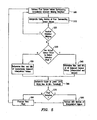
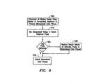
- FIG. 9 illustrates exemplary steps for performing bad pixel correction and demosaicing in a single stage.
- the processor receives the raw sensor values and interpolates all of the missing sensor values (as described above in connection with FIGs. 4-7) (step 900).
- the interpolated color planes are used to detect defective pixels (step 910), and if any defective pixels are detected (step 920), the sensor values of the defective pixels are replaced using replacement sensor values estimated from neighboring pixels (step 930).
- the corrected interpolated color planes are output as the demosaiced image (step 940) for use in later processing, such as compression or conversion for display on a display device.
Claims (10)
- Système de traitement d'image numérique (10) pour corriger des valeurs de capteurs (30) produites par des pixels (25) dans un réseau de pixels, chacun des pixels (25) dans le réseau de pixels produisant l'une respective des valeurs de capteurs (30) pour une image couleur, le système d'image numérique (10) comprenant un tampon (50) pour mémoriser au moins une partie des valeurs de capteurs (30) produites par les pixels (25) pour l'image, l'une des valeurs de capteurs (30) mémorisées étant une valeur de capteur (35) courante dans un premier plan couleur (80) produite par l'un courant des pixels (25) ; et un processeur (40) connecté pour recevoir les valeurs de capteurs (30) mémorisées dans le tampon (50), calculer des valeurs de capteurs interpolées (105) dans le premier plan couleur (80) pour les pixels (25) qui appartiennent à un plan de couleur différent du premier plan de couleur et qui sont spatialement adjacents au pixel courant (25) en utilisant les valeurs de capteurs (30) mémorisées, et déterminer si le pixel courant (25) est en défaut, caractérisé en ce que le processeur utilise les valeurs de capteurs interpolées pour déterminer si le pixel courant (25) est défectueux, et en ce que le processeur est agencé pour calculer les valeurs de capteurs interpolées (105) en utilisant une technique d'interpolation assurant que toutes les valeurs de capteurs en défaut restent isolées.
- Système de traitement d'image numérique (10) selon la revendication 1, dans lequel le processeur (40) est en outre agencé pour déterminer une quantité de seuil (125) et calculer une plage de valeurs de capteurs (115) pour le pixel courant (25) en utilisant au moins les valeurs interpolées (105), le pixel courant (25) étant défectueux quand la valeur de capteur courant (35) est à l'extérieur de la plage de valeurs de capteurs (115) de plus que la quantité de seuil (125).
- Système de traitement d'image numérique (10) selon la revendication 2, dans lequel le processeur (40) est en outre agencé pour remplacer la valeur courante (35a) du capteur par une valeur de remplacement (35b) du capteur calculée en utilisant les valeurs de capteurs interpolées (105) quand le pixel courant (25) est défectueux.
- Système de traitement d'image numérique selon la revendication 3, dans lequel le processeur (40) est en outre agencé pour supprimer l'effet de mosaïque des valeurs de capteurs (30) en utilisant les valeurs de capteurs interpolées (105) et la valeur de remplacement (35b) du capteur.
- Système de traitement d'image numérique (10) selon l'une quelconque des revendications précédentes, dans lequel le processeur (40) est en outre agencé pour calculer les valeurs de capteurs interpolées (105) en utilisant une technique d'interpolation médiane.
- Procédé pour corriger des valeurs de capteurs (30) produites par des pixels (25) dans un réseau de pixels, chacun des pixels (25) dans le réseau de pixels produisant l'une respective des valeurs de capteurs (30) pour une image couleur, ce procédé comprenant:recevoir (étape 300) au moins une partie des valeurs de capteurs (30) produites par les pixels (25) pour l'image, l'une des valeurs de capteurs (30) reçues étant une valeur courante de capteur (35) dans un premier plan couleur (80) produit par l'un courant des pixels (25);calculer (étape 310) des valeurs de capteurs interpolées (105) dans le premier plan couleur (80) pour des pixels (25) qui appartiennent à un plan couleur différent du premier plan couleur et qui sont spatialement adjacents au pixel courant (25) en utilisant les valeurs de capteurs (30) reçues ; etdéterminer (étapes 335 et 340) si le pixel courant (25) est défectueux,caractérisé par l'utilisation des valeurs de capteurs interpolées (105) pour déterminer si le pixel courant est défectueux, l'étape de calcul utilisant une technique d'interpolation assurant que toutes les valeurs de capteurs défectueuses restent isolées.
- Procédé selon la revendication 6, dans lequel l'étape de détermination comprend en outre :déterminer (étape 305) une quantité de seuil (125) ;calculer (étapes 315, 330) une plage de valeurs de capteurs (115) pour le pixel courant (25) en utilisant au moins lesdites valeurs de capteurs interpolées (105) ; etdéterminer (étapes 335, 340) que le pixel courant (25) est défectueux quand la valeur courante de capteur (35) est à l'extérieur de la plage de valeurs de capteurs (30) de plus que la quantité de seuil (125).
- Procédé selon la revendication 7, comprenant en outre:remplacer (étape 350) la valeur de capteur courante (35a) par une valeur de capteur de remplacement (35b) calculée en utilisant les valeurs de capteurs interpolées (105) quand le pixel courant (25) est défectueux.
- Procédé selon la revendication 8, comprenant en outre :supprimer l'effet de mosaïque (étape 930) des valeurs de capteurs (30) en utilisant les valeurs de capteurs interpolées (105) et la valeur de remplacement de capteur (35b).
- Procédé selon l'une des revendications 6 à 9, dans lequel le calcul comprend en outre le calcul (étape 310) des valeurs de capteurs interpolées (105) en utilisant une technique d'interpolation médiane.
Applications Claiming Priority (2)
| Application Number | Priority Date | Filing Date | Title |
|---|---|---|---|
| US222150 | 2002-08-16 | ||
| US10/222,150 US7015961B2 (en) | 2002-08-16 | 2002-08-16 | Digital image system and method for combining demosaicing and bad pixel correction |
Publications (3)
| Publication Number | Publication Date |
|---|---|
| EP1389771A2 EP1389771A2 (fr) | 2004-02-18 |
| EP1389771A3 EP1389771A3 (fr) | 2005-05-04 |
| EP1389771B1 true EP1389771B1 (fr) | 2007-07-04 |
Family
ID=30770648
Family Applications (1)
| Application Number | Title | Priority Date | Filing Date |
|---|---|---|---|
| EP03009920A Expired - Fee Related EP1389771B1 (fr) | 2002-08-16 | 2003-04-30 | Système et procédé de traitement d'images numériques permettant de combiner une operation de démosaiquage et une correction de mauvais pixels |
Country Status (4)
| Country | Link |
|---|---|
| US (1) | US7015961B2 (fr) |
| EP (1) | EP1389771B1 (fr) |
| JP (1) | JP4374488B2 (fr) |
| DE (1) | DE60314692T2 (fr) |
Families Citing this family (119)
| Publication number | Priority date | Publication date | Assignee | Title |
|---|---|---|---|---|
| US7283164B2 (en) * | 2002-09-18 | 2007-10-16 | Micron Technology, Inc. | Method for detecting and correcting defective pixels in a digital image sensor |
| JP4225795B2 (ja) * | 2003-01-22 | 2009-02-18 | オリンパス株式会社 | 撮像システム、画像処理プログラム |
| JP2004320128A (ja) * | 2003-04-11 | 2004-11-11 | Mega Chips Corp | 欠陥画素補正装置 |
| US9171577B1 (en) | 2003-04-25 | 2015-10-27 | Gopro, Inc. | Encoding and decoding selectively retrievable representations of video content |
| JP3914216B2 (ja) * | 2003-05-15 | 2007-05-16 | 松下電器産業株式会社 | 画像欠陥補正装置、及び、画像欠陥補正方法 |
| US8471852B1 (en) | 2003-05-30 | 2013-06-25 | Nvidia Corporation | Method and system for tessellation of subdivision surfaces |
| US7430334B2 (en) * | 2003-07-31 | 2008-09-30 | Hewlett Packard Development Company, L.P. | Digital imaging systems, articles of manufacture, and digital image processing methods |
| US7269295B2 (en) * | 2003-07-31 | 2007-09-11 | Hewlett-Packard Development Company, L.P. | Digital image processing methods, digital image devices, and articles of manufacture |
| US20050151860A1 (en) * | 2004-01-08 | 2005-07-14 | Silverstein D. A. | Image sensing device and method |
| US7369711B2 (en) * | 2004-02-26 | 2008-05-06 | Ge Medical Systems Global Technology Company, Llc | Asynchronous calibration and correction of a solid-state detector |
| DE102004015876A1 (de) * | 2004-03-31 | 2005-10-27 | Siemens Ag | Verfahren zum Auslesen eines Flächendetektors |
| JP2005354278A (ja) * | 2004-06-09 | 2005-12-22 | Seiko Epson Corp | 撮像手段の撮像した画像の画像データを処理する画像データ処理 |
| US8204306B2 (en) * | 2004-06-14 | 2012-06-19 | Xerox Corporation | Method for image segmentation based on block clustering for improved processing of touching characters |
| EP1613091B1 (fr) * | 2004-07-02 | 2009-08-26 | Mitsubishi Electric Information Technology Centre Europe B.V. | Prédiction intra-trame pour des trames filtrées passe-haut temporellement dans le codage vidéo par ondelettes |
| TWI256847B (en) * | 2004-08-30 | 2006-06-11 | Via Tech Inc | Method and apparatus for dynamically detecting pixel values |
| CN1301621C (zh) * | 2004-09-08 | 2007-02-21 | 威盛电子股份有限公司 | 动态检测像素数值的方法与装置 |
| JP4533124B2 (ja) * | 2004-12-21 | 2010-09-01 | イーストマン コダック カンパニー | 画素欠陥補正装置 |
| KR100636971B1 (ko) * | 2004-12-30 | 2006-10-19 | 매그나칩 반도체 유한회사 | 이미지센서의 포커스 데이타 생성 장치 및 방법 |
| JP4375269B2 (ja) * | 2005-03-29 | 2009-12-02 | セイコーエプソン株式会社 | 印刷制御方法、印刷制御装置、及び印刷制御プログラム |
| US7683948B2 (en) * | 2005-03-31 | 2010-03-23 | Freescale Semiconductor, Inc. | System and method for bad pixel replacement in image processing |
| JP4388909B2 (ja) * | 2005-04-25 | 2009-12-24 | イーストマン コダック カンパニー | 画素欠陥補正装置 |
| US8416323B2 (en) * | 2005-05-19 | 2013-04-09 | Mstar Semiconductor Inc. | Noise reduction method and noise reduction apparatus |
| US8274715B2 (en) | 2005-07-28 | 2012-09-25 | Omnivision Technologies, Inc. | Processing color and panchromatic pixels |
| US8139130B2 (en) | 2005-07-28 | 2012-03-20 | Omnivision Technologies, Inc. | Image sensor with improved light sensitivity |
| JP4985403B2 (ja) * | 2005-08-23 | 2012-07-25 | 株式会社ニコン | 画像処理システムおよび画像処理プログラム |
| JP4961182B2 (ja) * | 2005-10-18 | 2012-06-27 | 株式会社リコー | ノイズ除去装置、ノイズ除去方法、ノイズ除去プログラム及び記録媒体 |
| US8571346B2 (en) * | 2005-10-26 | 2013-10-29 | Nvidia Corporation | Methods and devices for defective pixel detection |
| US7885458B1 (en) | 2005-10-27 | 2011-02-08 | Nvidia Corporation | Illuminant estimation using gamut mapping and scene classification |
| US7750956B2 (en) * | 2005-11-09 | 2010-07-06 | Nvidia Corporation | Using a graphics processing unit to correct video and audio data |
| US20070133902A1 (en) * | 2005-12-13 | 2007-06-14 | Portalplayer, Inc. | Method and circuit for integrated de-mosaicing and downscaling preferably with edge adaptive interpolation and color correlation to reduce aliasing artifacts |
| US8588542B1 (en) | 2005-12-13 | 2013-11-19 | Nvidia Corporation | Configurable and compact pixel processing apparatus |
| CN100546335C (zh) * | 2005-12-21 | 2009-09-30 | 比亚迪股份有限公司 | 一种实现异常点数值校正的色彩插值方法 |
| US8737832B1 (en) * | 2006-02-10 | 2014-05-27 | Nvidia Corporation | Flicker band automated detection system and method |
| US8605797B2 (en) * | 2006-02-15 | 2013-12-10 | Samsung Electronics Co., Ltd. | Method and system for partitioning and encoding of uncompressed video for transmission over wireless medium |
| US8014597B1 (en) * | 2006-03-22 | 2011-09-06 | Woodman Labs | Method for efficient compression and decoding of single sensor color image data |
| CN101060643B (zh) * | 2006-04-17 | 2011-12-28 | 北京大学深圳研究生院 | 一种用于数字摄像的自适应坏点去除方法 |
| US7646910B1 (en) * | 2006-04-19 | 2010-01-12 | Ambarella, Inc. | Digital video camera non-integer-ratio Bayer domain scaler |
| US7756355B2 (en) * | 2006-05-05 | 2010-07-13 | Aptina Imaging Corp. | Method and apparatus providing adaptive noise suppression |
| US7916362B2 (en) * | 2006-05-22 | 2011-03-29 | Eastman Kodak Company | Image sensor with improved light sensitivity |
| DE102006028735B4 (de) * | 2006-06-20 | 2009-04-09 | Sci-Worx Gmbh | Einrichtung zur Interpolation und Filterung von digitalen Bilddaten |
| US20080158396A1 (en) * | 2006-08-07 | 2008-07-03 | Transchip, Inc. | Image Signal Processor For CMOS Image Sensors |
| US8594441B1 (en) | 2006-09-12 | 2013-11-26 | Nvidia Corporation | Compressing image-based data using luminance |
| US7649555B2 (en) * | 2006-10-02 | 2010-01-19 | Mtekvision Co., Ltd. | Apparatus for processing dead pixel |
| US8031258B2 (en) | 2006-10-04 | 2011-10-04 | Omnivision Technologies, Inc. | Providing multiple video signals from single sensor |
| US7925074B2 (en) * | 2006-10-16 | 2011-04-12 | Teradyne, Inc. | Adaptive background propagation method and device therefor |
| US20080100725A1 (en) * | 2006-10-27 | 2008-05-01 | Abadeer Wagdi W | Circuits for enhancing yield and performance of cmos imaging sensors |
| US20080215261A1 (en) * | 2006-10-27 | 2008-09-04 | International Business Machines Corporation | Design structure for enhancing yield and performance of cmos imaging sensors |
| US7860335B2 (en) * | 2006-12-04 | 2010-12-28 | The Boeing Company | Method and apparatus for smart signal averaging |
| US8723969B2 (en) * | 2007-03-20 | 2014-05-13 | Nvidia Corporation | Compensating for undesirable camera shakes during video capture |
| US8885076B2 (en) * | 2007-03-30 | 2014-11-11 | Hewlett-Packard Development Company, L.P. | Camera sensor defect correction and noise reduction |
| US8237830B2 (en) | 2007-04-11 | 2012-08-07 | Red.Com, Inc. | Video camera |
| ES2486295T3 (es) | 2007-04-11 | 2014-08-18 | Red.Com, Inc. | Cámara de vídeo |
| US8564687B2 (en) * | 2007-05-07 | 2013-10-22 | Nvidia Corporation | Efficient determination of an illuminant of a scene |
| US7889921B2 (en) * | 2007-05-23 | 2011-02-15 | Eastman Kodak Company | Noise reduced color image using panchromatic image |
| US8698917B2 (en) * | 2007-06-04 | 2014-04-15 | Nvidia Corporation | Reducing computational complexity in determining an illuminant of a scene |
| US8842739B2 (en) * | 2007-07-20 | 2014-09-23 | Samsung Electronics Co., Ltd. | Method and system for communication of uncompressed video information in wireless systems |
| US8724895B2 (en) | 2007-07-23 | 2014-05-13 | Nvidia Corporation | Techniques for reducing color artifacts in digital images |
| US8243823B2 (en) | 2007-08-29 | 2012-08-14 | Samsung Electronics Co., Ltd. | Method and system for wireless communication of uncompressed video information |
| US8570634B2 (en) * | 2007-10-11 | 2013-10-29 | Nvidia Corporation | Image processing of an incoming light field using a spatial light modulator |
| JP5180795B2 (ja) * | 2007-12-10 | 2013-04-10 | キヤノン株式会社 | 撮像装置及びその制御方法 |
| US9177368B2 (en) | 2007-12-17 | 2015-11-03 | Nvidia Corporation | Image distortion correction |
| US8780128B2 (en) * | 2007-12-17 | 2014-07-15 | Nvidia Corporation | Contiguously packed data |
| US8035704B2 (en) * | 2008-01-03 | 2011-10-11 | Aptina Imaging Corporation | Method and apparatus for processing a digital image having defective pixels |
| US8698908B2 (en) | 2008-02-11 | 2014-04-15 | Nvidia Corporation | Efficient method for reducing noise and blur in a composite still image from a rolling shutter camera |
| JP5056501B2 (ja) * | 2008-03-12 | 2012-10-24 | 株式会社Jvcケンウッド | 撮像装置及びこれに用いる欠陥画素補正方法 |
| JP5110289B2 (ja) * | 2008-03-24 | 2012-12-26 | 株式会社メガチップス | ノイズ低減装置およびデジタルカメラ |
| US9379156B2 (en) * | 2008-04-10 | 2016-06-28 | Nvidia Corporation | Per-channel image intensity correction |
| JP5311916B2 (ja) * | 2008-07-31 | 2013-10-09 | 株式会社エルモ社 | 撮像装置 |
| US8164660B2 (en) * | 2008-10-28 | 2012-04-24 | Omnivision Technologies, Inc. | Single row based defective pixel correction |
| US8373718B2 (en) | 2008-12-10 | 2013-02-12 | Nvidia Corporation | Method and system for color enhancement with color volume adjustment and variable shift along luminance axis |
| US9369759B2 (en) * | 2009-04-15 | 2016-06-14 | Samsung Electronics Co., Ltd. | Method and system for progressive rate adaptation for uncompressed video communication in wireless systems |
| US8749662B2 (en) | 2009-04-16 | 2014-06-10 | Nvidia Corporation | System and method for lens shading image correction |
| JP5169994B2 (ja) * | 2009-05-27 | 2013-03-27 | ソニー株式会社 | 画像処理装置、撮像装置及び画像処理方法 |
| US8698783B2 (en) * | 2009-10-07 | 2014-04-15 | Sharp Kabushiki Kaisha | Touch panel |
| US8698918B2 (en) * | 2009-10-27 | 2014-04-15 | Nvidia Corporation | Automatic white balancing for photography |
| JP5120441B2 (ja) * | 2009-11-26 | 2013-01-16 | 株式会社ニコン | 画像処理装置 |
| KR101696672B1 (ko) * | 2010-05-10 | 2017-01-17 | 삼성전자주식회사 | 영상 신호 처리 방법 및 이를 이용하는 영상 촬영 방법 |
| US8774544B1 (en) * | 2010-07-23 | 2014-07-08 | Xilinx, Inc. | Determining outlier pixels of successive frames |
| US8351696B2 (en) | 2010-09-17 | 2013-01-08 | Foveon, Inc. | Correcting defective pixels in digital color images |
| WO2012063265A2 (fr) * | 2010-11-12 | 2012-05-18 | Indian Institute Of Technology, Kharagpur | Procédé et appareil de détection de mauvais pixels dans un réseau de capteurs et d'annulation de l'erreur |
| US20120188406A1 (en) * | 2011-01-20 | 2012-07-26 | Apple Inc. | Reduced power consumption filter |
| JP5740465B2 (ja) * | 2011-02-28 | 2015-06-24 | 富士フイルム株式会社 | 撮像装置及び欠陥画素補正方法 |
| US8891866B2 (en) * | 2011-08-31 | 2014-11-18 | Sony Corporation | Image processing apparatus, image processing method, and program |
| TWI456991B (zh) | 2011-12-02 | 2014-10-11 | Ind Tech Res Inst | 壞點偵測方法與電腦程式產品 |
| WO2013099917A1 (fr) * | 2011-12-28 | 2013-07-04 | 富士フイルム株式会社 | Dispositif d'imagerie |
| US8976161B2 (en) | 2012-03-01 | 2015-03-10 | Apple Inc. | Systems and methods for image processing |
| US9798698B2 (en) | 2012-08-13 | 2017-10-24 | Nvidia Corporation | System and method for multi-color dilu preconditioner |
| US9508318B2 (en) | 2012-09-13 | 2016-11-29 | Nvidia Corporation | Dynamic color profile management for electronic devices |
| US9307213B2 (en) | 2012-11-05 | 2016-04-05 | Nvidia Corporation | Robust selection and weighting for gray patch automatic white balancing |
| TW201419853A (zh) * | 2012-11-09 | 2014-05-16 | Ind Tech Res Inst | 影像處理器及其影像壞點偵測方法 |
| JP2016508700A (ja) | 2013-02-14 | 2016-03-22 | レッド.コム,インコーポレイテッド | ビデオカメラ |
| DE102013209165A1 (de) * | 2013-05-17 | 2014-11-20 | Arnold & Richter Cine Technik Gmbh & Co. Betriebs Kg | Pixelkorrekturverfahren |
| US9418400B2 (en) | 2013-06-18 | 2016-08-16 | Nvidia Corporation | Method and system for rendering simulated depth-of-field visual effect |
| US9826208B2 (en) | 2013-06-26 | 2017-11-21 | Nvidia Corporation | Method and system for generating weights for use in white balancing an image |
| US9756222B2 (en) | 2013-06-26 | 2017-09-05 | Nvidia Corporation | Method and system for performing white balancing operations on captured images |
| US9996900B2 (en) | 2014-02-05 | 2018-06-12 | Nanyang Technological University | Methods and systems for demosaicing an image |
| KR20150141821A (ko) * | 2014-06-10 | 2015-12-21 | 삼성전자주식회사 | 불균일 특성을 보정하는 디스플레이 장치 및 그 제어 방법 |
| WO2016022374A1 (fr) * | 2014-08-05 | 2016-02-11 | Seek Thermal, Inc. | Réglage de contraste local pour des images numériques |
| FR3033116B1 (fr) | 2015-02-20 | 2017-03-24 | Stmicroelectronics (Grenoble 2) Sas | Procede de selection d’une solution de placement des pixels d’une image en fonction du rendu visuel |
| JP2017055309A (ja) | 2015-09-10 | 2017-03-16 | キヤノン株式会社 | 撮像装置及びその制御方法 |
| JP2017055308A (ja) * | 2015-09-10 | 2017-03-16 | キヤノン株式会社 | 撮像装置及びその制御方法 |
| KR102326167B1 (ko) * | 2015-11-10 | 2021-11-17 | 엘지디스플레이 주식회사 | 유기 발광 표시장치와 그 구동 방법 |
| WO2017125162A1 (fr) * | 2016-01-21 | 2017-07-27 | Sony Mobile Communications Inc. | Procédé et dispositif de suppression de mosaïques d'images en couleur |
| US10867371B2 (en) | 2016-06-28 | 2020-12-15 | Seek Thermal, Inc. | Fixed pattern noise mitigation for a thermal imaging system |
| US10158815B2 (en) * | 2016-07-18 | 2018-12-18 | Samsung Electronics Co., Ltd. | Method and system for bad pixel correction in image sensors |
| CN109565533B (zh) * | 2016-08-02 | 2021-04-16 | 株式会社富士 | 头分离型相机及作业机 |
| EP3649783A1 (fr) | 2017-07-05 | 2020-05-13 | Red.Com, Llc | Traitement de données d'image vidéo dans des dispositifs électroniques |
| KR102496377B1 (ko) | 2017-10-24 | 2023-02-06 | 삼성전자주식회사 | 저항변화 물질층을 가지는 비휘발성 메모리소자 |
| TWI670977B (zh) * | 2017-11-06 | 2019-09-01 | 瑞昱半導體股份有限公司 | 不良像素補償方法與裝置 |
| CN109788217B (zh) * | 2017-11-13 | 2021-05-25 | 瑞昱半导体股份有限公司 | 不良像素补偿方法与装置 |
| JP7081200B2 (ja) * | 2018-02-22 | 2022-06-07 | セイコーエプソン株式会社 | 画像表示装置、及び画像表示装置の制御方法 |
| KR20190137260A (ko) | 2018-06-01 | 2019-12-11 | 삼성전자주식회사 | 이미지 부호화 장치 및 이미지 복호화 장치 |
| US11748852B2 (en) * | 2018-06-27 | 2023-09-05 | Mitsubishi Electric Corporation | Pixel interpolation device and pixel interpolation method, and image processing device, and program and recording medium |
| US11276152B2 (en) | 2019-05-28 | 2022-03-15 | Seek Thermal, Inc. | Adaptive gain adjustment for histogram equalization in an imaging system |
| CN111340721B (zh) * | 2020-02-18 | 2021-02-12 | 国网电子商务有限公司 | 一种像素的修正方法、装置、设备及可读存储介质 |
| KR20220048496A (ko) | 2020-10-12 | 2022-04-20 | 삼성전자주식회사 | 이미지 센서의 프로세서, 이미지 처리 장치 및 이의 제어 방법 |
| KR102604109B1 (ko) * | 2020-12-09 | 2023-11-21 | 에스케이하이닉스 주식회사 | 이미지 센싱 장치 |
| US11252359B1 (en) * | 2021-06-21 | 2022-02-15 | Allegro Microsystems, Llc | Image compensation for sensor array having bad pixels |
| CN114038428A (zh) * | 2021-11-24 | 2022-02-11 | 惠州华星光电显示有限公司 | 显示面板的补偿方法及补偿装置 |
Family Cites Families (10)
| Publication number | Priority date | Publication date | Assignee | Title |
|---|---|---|---|---|
| GB8614212D0 (en) | 1986-06-11 | 1986-07-16 | Kodak Ltd | Image processing method |
| EP0496573B1 (fr) * | 1991-01-24 | 1995-12-20 | Matsushita Electric Industrial Co., Ltd. | Circuit pour l'élimination de défauts des éléments d'images pour détecteur d'image en technique état solide |
| US5652621A (en) | 1996-02-23 | 1997-07-29 | Eastman Kodak Company | Adaptive color plane interpolation in single sensor color electronic camera |
| JP4115574B2 (ja) * | 1998-02-02 | 2008-07-09 | オリンパス株式会社 | 撮像装置 |
| GB9825086D0 (en) | 1998-11-17 | 1999-01-13 | Vision Group Plc | Defect correction in electronic imaging systems |
| US6806902B1 (en) * | 1999-06-08 | 2004-10-19 | Chrontel, Inc. | System and method for correcting bad pixel data in a digital camera |
| US6724945B1 (en) * | 2000-05-24 | 2004-04-20 | Hewlett-Packard Development Company, L.P. | Correcting defect pixels in a digital image |
| JP2002010274A (ja) * | 2000-06-20 | 2002-01-11 | Olympus Optical Co Ltd | カラー画像処理装置 |
| JP2002027324A (ja) | 2000-07-04 | 2002-01-25 | Victor Co Of Japan Ltd | 不良画素補正装置及び方法 |
| US6985180B2 (en) * | 2001-06-19 | 2006-01-10 | Ess Technology, Inc. | Intelligent blemish control algorithm and apparatus |
-
2002
- 2002-08-16 US US10/222,150 patent/US7015961B2/en active Active
-
2003
- 2003-04-30 EP EP03009920A patent/EP1389771B1/fr not_active Expired - Fee Related
- 2003-04-30 DE DE60314692T patent/DE60314692T2/de not_active Expired - Lifetime
- 2003-07-17 JP JP2003198261A patent/JP4374488B2/ja not_active Expired - Fee Related
Non-Patent Citations (2)
| Title |
|---|
| KALEVO O.; RANTANEN H.: "Noise Reduction Techniques for Bayer-Matrix Images", PROC. OF THE SPIE, vol. 4669, 23 January 2002 (2002-01-23), pages 348 - 359, XP009004110 * |
| LONGERE P. ET AL: "Perceptual assessment of demosaicing algorithm performance", PROCEEDINGS OF THE IEEE, vol. 90, no. 1, January 2002 (2002-01-01), pages 123 - 132 * |
Also Published As
| Publication number | Publication date |
|---|---|
| EP1389771A2 (fr) | 2004-02-18 |
| DE60314692T2 (de) | 2008-04-10 |
| DE60314692D1 (de) | 2007-08-16 |
| US7015961B2 (en) | 2006-03-21 |
| JP2004080761A (ja) | 2004-03-11 |
| JP4374488B2 (ja) | 2009-12-02 |
| EP1389771A3 (fr) | 2005-05-04 |
| US20040032516A1 (en) | 2004-02-19 |
Similar Documents
| Publication | Publication Date | Title |
|---|---|---|
| EP1389771B1 (fr) | Système et procédé de traitement d'images numériques permettant de combiner une operation de démosaiquage et une correction de mauvais pixels | |
| JP4378746B2 (ja) | 欠陥ピクセルの検出可能なディジタル・イメージ・センサおよび方法 | |
| EP1416739B1 (fr) | Interpolation de couleurs pour des capteurs d'images utilisant une méthode de régression lineaire locale | |
| KR101012537B1 (ko) | 고체 이미지 센서 | |
| US6781626B1 (en) | System and method of color interpolation | |
| US8253828B2 (en) | Image capture device including edge direction determination unit, and image processing method for the same | |
| USRE44717E1 (en) | Edge detecting method | |
| US6757012B1 (en) | Color selection for sparse color image reconstruction | |
| US20080278609A1 (en) | Imaging apparatus, defective pixel correcting apparatus, processing method in the apparatuses, and program | |
| EP1729523B1 (fr) | Procede de traitement d'image | |
| US8212899B2 (en) | Imaging apparatus capable of highly accurate defective pixel correction processing | |
| US20170078596A1 (en) | Adaptive shading correction | |
| USRE43239E1 (en) | Color interpolation method of image sensor | |
| JP4104495B2 (ja) | データ処理装置、画像処理装置およびカメラ | |
| US20090097743A1 (en) | Method and apparatus providing hardware-efficient demosaicing of image data | |
| US8400534B2 (en) | Noise reduction methods and systems for imaging devices | |
| US8086034B2 (en) | System and method for reducing color artifacts in digital images | |
| US8938120B2 (en) | Image sensing device and image data processing method using the same | |
| JP2004159176A (ja) | ノイズ除去方法、撮像装置およびノイズ除去プログラム | |
| CN117041745A (zh) | 智能影像处理中的颜色插值方法及装置 | |
| EP2257044A1 (fr) | Procédé et dispositif de traitement d'une valeur de sortie brute d'un pixel cible |
Legal Events
| Date | Code | Title | Description |
|---|---|---|---|
| PUAI | Public reference made under article 153(3) epc to a published international application that has entered the european phase |
Free format text: ORIGINAL CODE: 0009012 |
|
| AK | Designated contracting states |
Kind code of ref document: A2 Designated state(s): AT BE BG CH CY CZ DE DK EE ES FI FR GB GR HU IE IT LI LU MC NL PT RO SE SI SK TR |
|
| AX | Request for extension of the european patent |
Extension state: AL LT LV MK |
|
| PUAL | Search report despatched |
Free format text: ORIGINAL CODE: 0009013 |
|
| AK | Designated contracting states |
Kind code of ref document: A3 Designated state(s): AT BE BG CH CY CZ DE DK EE ES FI FR GB GR HU IE IT LI LU MC NL PT RO SE SI SK TR |
|
| AX | Request for extension of the european patent |
Extension state: AL LT LV MK |
|
| 17P | Request for examination filed |
Effective date: 20050606 |
|
| AKX | Designation fees paid |
Designated state(s): DE FR GB |
|
| GRAP | Despatch of communication of intention to grant a patent |
Free format text: ORIGINAL CODE: EPIDOSNIGR1 |
|
| RAP1 | Party data changed (applicant data changed or rights of an application transferred) |
Owner name: AGILENT TECHNOLOGIES, INC. |
|
| GRAS | Grant fee paid |
Free format text: ORIGINAL CODE: EPIDOSNIGR3 |
|
| GRAA | (expected) grant |
Free format text: ORIGINAL CODE: 0009210 |
|
| AK | Designated contracting states |
Kind code of ref document: B1 Designated state(s): DE FR GB |
|
| REG | Reference to a national code |
Ref country code: GB Ref legal event code: FG4D |
|
| REF | Corresponds to: |
Ref document number: 60314692 Country of ref document: DE Date of ref document: 20070816 Kind code of ref document: P |
|
| ET | Fr: translation filed | ||
| PLBE | No opposition filed within time limit |
Free format text: ORIGINAL CODE: 0009261 |
|
| STAA | Information on the status of an ep patent application or granted ep patent |
Free format text: STATUS: NO OPPOSITION FILED WITHIN TIME LIMIT |
|
| 26N | No opposition filed |
Effective date: 20080407 |
|
| REG | Reference to a national code |
Ref country code: GB Ref legal event code: 732E |
|
| REG | Reference to a national code |
Ref country code: FR Ref legal event code: TP |
|
| REG | Reference to a national code |
Ref country code: FR Ref legal event code: RM |
|
| REG | Reference to a national code |
Ref country code: GB Ref legal event code: 732E Free format text: REGISTERED BETWEEN 20101007 AND 20101013 |
|
| REG | Reference to a national code |
Ref country code: FR Ref legal event code: PLFP Year of fee payment: 14 |
|
| REG | Reference to a national code |
Ref country code: FR Ref legal event code: PLFP Year of fee payment: 15 |
|
| REG | Reference to a national code |
Ref country code: FR Ref legal event code: PLFP Year of fee payment: 16 |
|
| PGFP | Annual fee paid to national office [announced via postgrant information from national office to epo] |
Ref country code: GB Payment date: 20200323 Year of fee payment: 18 |
|
| PGFP | Annual fee paid to national office [announced via postgrant information from national office to epo] |
Ref country code: FR Payment date: 20200319 Year of fee payment: 18 |
|
| PGFP | Annual fee paid to national office [announced via postgrant information from national office to epo] |
Ref country code: DE Payment date: 20200319 Year of fee payment: 18 |
|
| REG | Reference to a national code |
Ref country code: DE Ref legal event code: R119 Ref document number: 60314692 Country of ref document: DE |
|
| GBPC | Gb: european patent ceased through non-payment of renewal fee |
Effective date: 20210430 |
|
| PG25 | Lapsed in a contracting state [announced via postgrant information from national office to epo] |
Ref country code: DE Free format text: LAPSE BECAUSE OF NON-PAYMENT OF DUE FEES Effective date: 20211103 Ref country code: GB Free format text: LAPSE BECAUSE OF NON-PAYMENT OF DUE FEES Effective date: 20210430 Ref country code: FR Free format text: LAPSE BECAUSE OF NON-PAYMENT OF DUE FEES Effective date: 20210430 |