EP1389599A2 - Passive Vorrichtung zum Vereinzeln von Aufzeichnungsträgern - Google Patents
Passive Vorrichtung zum Vereinzeln von Aufzeichnungsträgern Download PDFInfo
- Publication number
- EP1389599A2 EP1389599A2 EP03016941A EP03016941A EP1389599A2 EP 1389599 A2 EP1389599 A2 EP 1389599A2 EP 03016941 A EP03016941 A EP 03016941A EP 03016941 A EP03016941 A EP 03016941A EP 1389599 A2 EP1389599 A2 EP 1389599A2
- Authority
- EP
- European Patent Office
- Prior art keywords
- media
- separator
- formations
- separating device
- stack
- Prior art date
- Legal status (The legal status is an assumption and is not a legal conclusion. Google has not performed a legal analysis and makes no representation as to the accuracy of the status listed.)
- Withdrawn
Links
Images


Classifications
-
- B—PERFORMING OPERATIONS; TRANSPORTING
- B65—CONVEYING; PACKING; STORING; HANDLING THIN OR FILAMENTARY MATERIAL
- B65H—HANDLING THIN OR FILAMENTARY MATERIAL, e.g. SHEETS, WEBS, CABLES
- B65H3/00—Separating articles from piles
- B65H3/46—Supplementary devices or measures to assist separation or prevent double feed
- B65H3/56—Elements, e.g. scrapers, fingers, needles, brushes, acting on separated article or on edge of the pile
-
- B—PERFORMING OPERATIONS; TRANSPORTING
- B65—CONVEYING; PACKING; STORING; HANDLING THIN OR FILAMENTARY MATERIAL
- B65H—HANDLING THIN OR FILAMENTARY MATERIAL, e.g. SHEETS, WEBS, CABLES
- B65H3/00—Separating articles from piles
- B65H3/46—Supplementary devices or measures to assist separation or prevent double feed
- B65H3/52—Friction retainers acting on under or rear side of article being separated
- B65H3/5207—Non-driven retainers, e.g. movable retainers being moved by the motion of the article
- B65H3/5215—Non-driven retainers, e.g. movable retainers being moved by the motion of the article the retainers positioned under articles separated from the top of the pile
-
- B—PERFORMING OPERATIONS; TRANSPORTING
- B65—CONVEYING; PACKING; STORING; HANDLING THIN OR FILAMENTARY MATERIAL
- B65H—HANDLING THIN OR FILAMENTARY MATERIAL, e.g. SHEETS, WEBS, CABLES
- B65H2402/00—Constructional details of the handling apparatus
- B65H2402/30—Supports; Subassemblies; Mountings thereof
- B65H2402/32—Sliding support means
-
- B—PERFORMING OPERATIONS; TRANSPORTING
- B65—CONVEYING; PACKING; STORING; HANDLING THIN OR FILAMENTARY MATERIAL
- B65H—HANDLING THIN OR FILAMENTARY MATERIAL, e.g. SHEETS, WEBS, CABLES
- B65H2405/00—Parts for holding the handled material
- B65H2405/10—Cassettes, holders, bins, decks, trays, supports or magazines for sheets stacked substantially horizontally
- B65H2405/11—Parts and details thereof
- B65H2405/113—Front, i.e. portion adjacent to the feeding / delivering side
- B65H2405/1132—Front, i.e. portion adjacent to the feeding / delivering side with stepped surface portions
-
- B—PERFORMING OPERATIONS; TRANSPORTING
- B65—CONVEYING; PACKING; STORING; HANDLING THIN OR FILAMENTARY MATERIAL
- B65H—HANDLING THIN OR FILAMENTARY MATERIAL, e.g. SHEETS, WEBS, CABLES
- B65H2405/00—Parts for holding the handled material
- B65H2405/10—Cassettes, holders, bins, decks, trays, supports or magazines for sheets stacked substantially horizontally
- B65H2405/11—Parts and details thereof
- B65H2405/113—Front, i.e. portion adjacent to the feeding / delivering side
- B65H2405/1134—Front, i.e. portion adjacent to the feeding / delivering side movable, e.g. pivotable
-
- B—PERFORMING OPERATIONS; TRANSPORTING
- B65—CONVEYING; PACKING; STORING; HANDLING THIN OR FILAMENTARY MATERIAL
- B65H—HANDLING THIN OR FILAMENTARY MATERIAL, e.g. SHEETS, WEBS, CABLES
- B65H2405/00—Parts for holding the handled material
- B65H2405/10—Cassettes, holders, bins, decks, trays, supports or magazines for sheets stacked substantially horizontally
- B65H2405/11—Parts and details thereof
- B65H2405/113—Front, i.e. portion adjacent to the feeding / delivering side
- B65H2405/1136—Front, i.e. portion adjacent to the feeding / delivering side inclined, i.e. forming an angle different from 90 with the bottom
-
- B—PERFORMING OPERATIONS; TRANSPORTING
- B65—CONVEYING; PACKING; STORING; HANDLING THIN OR FILAMENTARY MATERIAL
- B65H—HANDLING THIN OR FILAMENTARY MATERIAL, e.g. SHEETS, WEBS, CABLES
- B65H2405/00—Parts for holding the handled material
- B65H2405/10—Cassettes, holders, bins, decks, trays, supports or magazines for sheets stacked substantially horizontally
- B65H2405/14—Details of surface
- B65H2405/141—Reliefs, projections
Definitions
- the present invention relates to media handling devices such as printers, copiers, fax machines and the like, and, more particularly, the present invention relates to media separating devices used in the feed mechanisms for such machines.
- Printers, copiers, fax machines, scanners and the like use a variety of different pick mechanisms to deliver individual sheets of media to a delivery or indexing system. It is known to provide a stack of media in a tray, which may be vertical, horizontal or at some angle therebetween, and to feed individual sheets from the stack to the device. For trouble free operation of the device, it is necessary that only a single sheet be fed at a time. Thus, the pick mechanism and sheet feed structure must include some means for individualizing or separating a single sheet from the stack of sheets. In very high-speed devices that are often costly, it is known to use sheet feeders having relatively complex mechanical mechanisms for separating the individual sheets. However, there is a need also for lower cost printers, copiers, fax machines and the like. These machines must also separate and feed media reliably, but with less expensive and less complicated mechanisms. Therefore, simple, reliable, inexpensive sheet separating devices are required.
- Passive separation devices are known to have a slanted rubber element against which an advancing piece of media is driven.
- the media is driven from the top of a stack of media by a spring-biased feeding wheel. Separation occurs from the friction of the advancing media edge against the rubber surface. The angle of the rubber surface in relation to the advancing media and the frictional coefficient of the rubber impact the performance of such devices. If the media stack is large, the stack covers much of the rubber surface, and the exposed distance over which separation can occur is small. Further, the feed wheel rides on top of the media stack, biased thereagainst by a spring. When the media stack is tall, the spring force exerted against the stack through the drive wheel is large and friction between sheets is high.
- sheet feed devices can be horizontal, vertical or at some angle between horizontal and vertical.
- printers, copiers and fax machines it is common and desirable for the devices such as printers, copiers and fax machines to process a variety of different materials.
- a printer may routinely handle relatively lightweight, draft grade papers, heavier weight bond papers, card stock, transparencies and envelopes.
- separating devices While known separating devices have functioned satisfactorily to some extent, as speeds increase more definite reliable separation is required. Further, it is desirable that the separating device function consistently with different types of media, from the top piece of media in a stack to the bottom piece of media in the stack.
- the present invention provides a passive media-separating device having a formed surface to separate and maintain separation between individual media fed from a stack of media.
- the present invention provides a media-separating device for a media feeder in a media-processing device wherein individual pieces of media are picked from a stack of media and advanced for individual handing in the media-processing device.
- the separating device has a separator with a surface thereof disposed in a substantially confronting position relative to the stack of media, to confront the leading edges of pieces of media removed the stack.
- An array of formations is provided on the surface of the separator. Each formation includes a blocking surface positioned for confronting the leading edges of the moving media, a passing surface in a substantially non-confronting position relative to the leading edges of the media, and an apex at a connection between the blocking and passing surfaces.
- the apex is positioned relative to the passing surface and the movement of the leading edges for directing the leading edges over the passing surface.
- the array provides a succession of the formations along a path of travel by the leading edges of media removed from the stack.
- Means are provided for driving pieces of media from the stack against the separator.
- the present invention provides a media feeder for a media processing device with a media tray for holding a stack of media, a feeding mechanism for moving a first piece of media from the stack toward a discharge point and a media separating device.
- the media separating device includes a surface facing leading edges of media in a stack of media held in the tray.
- the surface includes a series of surface formations. Each formation includes a blocking surface positioned for confronting the leading edges of the moving media, a passing surface in a substantially non-confronting position relative to the leading edges of the media and an apex at a connection between the blocking and passing surfaces.
- the apex is positioned relative to the passing surface and the movement of the leading edges for directing the leading edges over the passing surface.
- the present invention provides a media separating device assembly for a media feeder.
- the assembly has a separator holder including a panel defining a slot; sides on opposite edges of the panel and blocks on a surface of the panel.
- the blocks are disposed on opposite sides of the slot near one end of the slot.
- Each block has an angular surface angling from one of the sides inwardly toward the slot and outwardly toward the one end.
- a separator component is slidable relative to the panel between the sides.
- the separator component includes an elongated separator have an array of formations thereon.
- the separator is positioned in the slot with the formations projecting beyond an opposite surface of the panel. Arms connected to the separator extend along and spaced from the separator. Tips of the arms engage the angular surfaces of the blocks.
- An advantage of the present invention is providing a passive media-separating device that is simple, inexpensive, easily installed, and consistent in performance.
- Another advantage of the present invention is providing a media-separating device that works effectively on a wide range of media types, including heavier and lighter weight media.
- a further advantage of the present invention is providing a media-separating device that provides a barricade against improper loading of a paper tray.
- Yet another advantage of the present invention is providing a media-separating device that works effectively on all pieces of media in a stack, from the top pieces in a full media tray to the bottom pieces in the media tray.
- Still another advantage of the present invention is providing a media-separating device that works effectively on a variety of media feeders, including both horizontal feeders and vertical feeders.
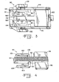
- a passive media separating device 10 in accordance with the present invention is shown in a media feeder 12 of a media-processing device 14 including frame members 16.
- Media processing device 14 can be a printer, copier, fax machine, scanner or other machine in which media is processed individually in some manner.
- media feeder 12 can be provided for feeding clean pieces of media such as paper of various weights, envelopes, card stock, transparencies, or the like for receiving printing thereon in a printer, fax machine, copier, etc.
- media feeder 12 can be provided for feeding original documents to be scanned, copied, faxed or the like.
- Media separating device 10 works well for many applications in which media of some type is removed from a media stack and fed individually for further processing.
- Media feeder 12 illustrated in Fig. 1 is a horizontal feeder having a horizontal media tray 18, which may be integral with frame 16, or removable from frame members 16.
- a media stack 20 including a plurality of individual pieces of media 22 is placed in media tray 18, and individual pieces of media 22 are removed, one by one, from media stack 20 for use in downstream functions (not shown) of media processing device 14.
- Media tray 18 has a discharge end 24 at which separating device 10 of the present invention is positioned, to operate on individual pieces of media 22 to cause separation thereof from stack 20.
- Media tray 18 has a substantially horizontal, fixed position bottom 26.
- Media tray 18 also includes side positioning means (not shown) for media stack 20, as those skilled in the art will understand readily.
- Media feeder 12 further includes a feeding mechanism 28 including a feeding roll 30 that operates against the top piece of media 22 in media stack 20.
- Feeding roll 30 is directly or indirectly secured to one of the frame members 16, and is biased by a spring 32 against stack 20.
- Feeding roll 30 is rotatably driven by drive means (not shown) to rotate in the direction indicated by arrow 34 about an axis 36.
- Feeding roll 30 is provided with a peripheral surface 38 of rubber, plastic or other material to create sufficient friction between roll 30 and media 22 so that rotation of roll 30 drives the top piece of media 22 toward discharge end 24 of media tray 18.
- feeding mechanism 28 can be of other designs than that shown, which is only exemplary and not limiting of the present invention.
- the present invention can be used on media feeders of various types, including different feeding mechanisms.
- FIG. 1 A first embodiment of the present invention is shown in Figs. 1 and 2.
- Media separating device 10 includes a separator 50 mounted in media tray 18 at discharge end 24. Separator 50 is disposed at an outwardly reclining angle with respect to tray bottom 26, and has a surface 52 facing media stack 20.
- Surface 52 has an array of formations 54 thereon which engage media 22 to cause separation of individual pieces of media 22 from media stack 20. Formations 54 provide a series of surface segments of distinctly different slopes, and operate with segments of surface 52 between adjacent formations 54 to control bending or deflection of each piece of media 22 as it is driven thereagainst by feeding mechanism 28.
- FIG. 2 an enlarged portion of separator 50 is shown, with two formations 54 shown on a portion of surface 52 thereof. Formations 54 are spaced from each other along surface 52, with an exposed segment of surface 52 between adjacent formations 54. Formations 54 are generally triangular shaped bodies projecting from surface 52 toward media stack 20. Each formation 54 presents a substantially blunt or blocking surface 56 facing toward and confronting media stack 20. Blocking surface 56 inhibits or blocks forward moving pieces of media 22. Each formation 54 further includes a passing surface 58 positioned in a non-confronting orientation to advancing media 22. Passing surface 58 provides little or no hindrance to forward moving pieces of media 22. A curved apex 60 connects surfaces 56 and 58.
- Fig. 2 further illustrates some dimensional interrelationships for separator 50 that have been found to provide good performance with a range of standard types of media 22 commonly used.
- Arrowed line 62 represents the greatest dimension of formation 54 from surface 52, preferably between about 0.15mm and 0.75mm.
- Segmented arrowed line 64 represents the vertical height of formation 54 between the points at which surfaces 56 and 58 are connected to surface 52, which height is preferably between about 0.5mm and 15mm.
- Arrowed line 66 represents the vertical distance between the points at which adjacent formations 54 are connected to surface 52, such distance preferably being between about 0.1mm and 0.5mm.
- Segmented curved line 68 represents the angle between blocking surface 56 and a piece of media 22 passing over apex 60 and against the lowermost edge of blocking surface 56, the angle preferably being between about 60 degrees and 135 degrees.
- Opposed arrows 70 represent the thickness of media 22, and opposed arrows 72 represent the vertical distance between apex 60 of one formation 54 and the point at which blocking surface 56 is joined to surface 52. Preferably, the distance represented by opposed arrows 72 is greater than the distance represented by opposed arrows 70.
- Segmented curved line 74 designates the incline angle of surface 52 from the plane of tray bottom 26.
- Oppositely directed arrowed lines 76 designate the length of blocking surface 56.
- the preferred length of blocking surface 56 represented by arrowed lines 76 appears to be related to the incline angle of surface 52, represented by segmented curved line 74, although no direct mathematical relationship has been determined.
- the length of blocking surface 56 represented by arrowed lines 76 is longer for shallower angles of inclination represented by segmented curved line 74, and can be shorter for steeper angles of inclination represented by segmented curved line 74.
- feeding mechanism 28 is operatively engaged against the uppermost sheet of media 22 in media stack 20.
- Rotation of feeding roll 30 causes one or several sheets of media 22 to move toward discharge end 24 of tray 18.
- a leading edge of each advancing piece of media 22 abuts against surface 52 or blocking surface 56, causing upward deflection of leading edge.
- Continued advancement of media 22 causes leading edge to slide against segments of surface 52 between adjacent formations 54, and along blocking surfaces 56 of successive formations 54.
- An uppermost piece of media 22 eventually slides over apex 60 of one formation 54, with directs media 22 to slide rapidly over passing surface 58 of the same formation 54 to abut against surface 52 or a next formation 54 immediately thereabove.
- any piece of media 22 below the upper most media 22 is delayed slightly as the leading edge continues to engage blocking surface 56 of the lower formation 54.
- a shingling effect occurs between all adjacent pieces of media 22, with an uppermost piece of media 22 of each adjacent pair of media 22 advancing beyond the lower piece of the pair.
- Such shingling effect increases as pieces of media 22 advance from formation 54 to formation 54 along separator 50.
- the top piece of media 22 advances over an uppermost formation 54 of separator 20, and is grasped by media handling structures (not shown) outside of tray 18. At this point the top piece of media 22 has been separated sufficiently from any and all pieces of media 22 below it so that only the single uppermost piece of media 22 is removed from tray 18.
- FIG 1 illustrates somewhat schematically a spring means allowing separator 50 to yield slightly if sufficient force is applied thereagainst by advancing media 22.
- Separator 50 slides generally along a plane parallel to surface 52, which is along the angle of inclination of separator 50.
- FIG. 3 A preferred assembly 90 for a media-separating device in accordance with the present invention is illustrated in Fig. 3.
- Assembly 90 includes a separator component 92 and a holder 94 therefor.
- Separator component 92 can be provided as a monolithic structure of plastic or the like, and includes a separator 50 as described previously, including formations 54 thereon.
- Separator component 92 further includes lateral fins 96 and 98 at a lower end thereof, and arms 100 and 102 connected by shoulders 104 and 106, respectively, to separator 50. Shoulders 104 and 106 are connected to separator 50 at a center portion of separator 50, and extend outwardly from separator 50.
- Arms 100 and 102 extend from shoulders 104 and 106 toward an upper end of separator 50, substantially parallel to but spaced from separator 50. Arms 100, 102 and shoulders 104, 106 can deflect from force applied against the distal ends of arms 100 and 102. Tips 108 and 110 of arms 100 and 102, respectively, preferably are provided in curved (Fig. 3) or angled (Fig. 4) formations.
- Holder 94 is a somewhat box-like structure for holding and directing movement of separator component 92.
- Holder 94 has a panel 112 and sides 114 and 116 between which separator component 92 can slide.
- Panel 112 defines a slot 118 through which separator 50 projects. Slot 118 is longer than separator 50, allowing axial movement of separator 50 along and within slot 118.
- a stop 120 is provided on panel 112, near a lower end of slot 118.
- Angular blocks 122 and 124 are provided on panel 112 at an upper end thereof, just outwardly from slot 118.
- Fig. 7 illustrates a passive media-separating device 134 of the present invention operating on a vertical media feeder 136 of a media-processing device 138.
- the embodiment illustrated in Fig. 7 is similar to that described previously herein, except that media feeder 136 illustrated in Fig. 7 is a vertical feeder having a substantially vertically oriented media stack 140 positioned against a substantially vertical support 142.
- a bottom 144 supports edges of some or all individual pieces of media 146 in stack 140. Individual pieces of media 146 are removed, one by one, from media stack 140 for use in downstream functions of media processing device 138.
- Media feeder 136 has a discharge side 148, and separating device 134 of the present invention is positioned along a bottom of media stack 140, between discharge side 148 and bottom 144.
- media stack 140 can be positioned against a first length of separating device 134 indicated by line 150. As can be seen from Fig. 7, initial shingling of individual pieces of media 146 occurs along the first length of separating device 134 from the positioning of any portion of media stack 140 thereagainst.
- Media feeder 136 further includes a feeding mechanism 152 including a feeding roll 154 that operates against media stack 140.
- Feeding roll 154 is biased by a spring 156 against stack 140.
- Feeding roll 154 is rotatably driven by drive means (not shown) to rotate in the direction indicated by arrow 158 about an axis 160.
- Feeding roll 154 is provided with a peripheral surface 162 of rubber, plastic or other material to creating sufficient friction between roll 154 and media 146 so that rotation of roll 154, together with the force of gravity, drives the outermost piece of media 146 toward discharge side 148.
- Separating device 134 includes a separator 164 having a surface 166 facing media stack 140.
- Surface 166 has an array of formations 168 extending therealong to discharge side 148. Separating device 134 operates similarly to separating device 10, to cause progressively increasing shingling of media 146 being moved toward discharge side 148 by feeding mechanism 152.
- a modified separator 170 (Fig. 8) formations 54 as described previously, are provided along an upper portion of separator 170, and along a lower portion thereof, designated by arrowed line 172, modified formations 174 are provided.
- Each formation 174 has a truncated apex 176, the truncations of which increase from the last of formations 54 toward the lower end of separator 170.
- Progressively increasing truncated apexes 176 promote removal and separation of media 22 at the lower end of media stack 20, where the force of engagement between feeding roll 30 and the uppermost piece of media 22 has lessened.
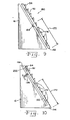
- a media separating device 180 is provided with a pivotally mounted separator 182 having a surface 52 and projections 54 and 174 similar to those described previously herein. Separator 182 is connected to frame member 16 only by an axis 184 about which separator 182 can pivot Spring means (not shown) can be provided along and associated with pivotal movement about axis 184, or between separator 182 and frame member 16.
- a media separating device 190 is provided with a cantilevered separator 192 having a surface 52 and projections 54 and 174 similar to those described previously herein.
- Cantilevered separator 192 is connected to frame 16 at a lower end 194 of separator 192, but is otherwise unattached, defining a space 196 between frame 16 and separator 192.
- Springing deflection of separator 192 occurs at lower end 194.
- Further assistance can be provided with a spring 198 near distal end 200 of separator 192, to provide more robust resistance to deflection of cantilevered separator 192.
- Springs 198 of different spring force can be used, depending upon the types of media to be separated by separating device 190.
- the present invention provides a media-separating device that works effectively for different types of media from the top piece of media in a media stack to the bottom piece of media in the stack.
- the device is mechanically simple, and can be provided inexpensively, for a variety of different feed mechanisms and media feeders.
- the blunt blocking surfaces of the separators provide abutments against which a stack of media can be placed, and thereby prevent heretofore experienced disadvantages of other separators in such conditions.
Landscapes
- Engineering & Computer Science (AREA)
- Mechanical Engineering (AREA)
- Sheets, Magazines, And Separation Thereof (AREA)
- Advancing Webs (AREA)
Applications Claiming Priority (4)
| Application Number | Priority Date | Filing Date | Title |
|---|---|---|---|
| US40393102P | 2002-08-16 | 2002-08-16 | |
| US403931P | 2002-08-16 | ||
| US10/454,180 US7036814B2 (en) | 2002-08-16 | 2003-06-04 | Passive media separating device |
| US454180 | 2003-06-04 |
Publications (2)
| Publication Number | Publication Date |
|---|---|
| EP1389599A2 true EP1389599A2 (de) | 2004-02-18 |
| EP1389599A3 EP1389599A3 (de) | 2004-12-08 |
Family
ID=30773143
Family Applications (1)
| Application Number | Title | Priority Date | Filing Date |
|---|---|---|---|
| EP03016941A Withdrawn EP1389599A3 (de) | 2002-08-16 | 2003-07-25 | Passive Vorrichtung zum Vereinzeln von Aufzeichnungsträgern |
Country Status (3)
| Country | Link |
|---|---|
| US (1) | US7036814B2 (de) |
| EP (1) | EP1389599A3 (de) |
| JP (1) | JP4053952B2 (de) |
Cited By (3)
| Publication number | Priority date | Publication date | Assignee | Title |
|---|---|---|---|---|
| EP1580154A1 (de) * | 2004-03-05 | 2005-09-28 | Brother Kogyo Kabushiki Kaisha | Bogentrennglied und -zuführvorrichtung |
| CN101844686A (zh) * | 2009-03-26 | 2010-09-29 | 兄弟工业株式会社 | 纸张分离装置、具有该装置的供纸盘及供纸装置 |
| CN102134012A (zh) * | 2010-01-25 | 2011-07-27 | 精工爱普生株式会社 | 片材进送装置及记录装置 |
Families Citing this family (31)
| Publication number | Priority date | Publication date | Assignee | Title |
|---|---|---|---|---|
| US7193834B2 (en) * | 2003-01-17 | 2007-03-20 | Illinois Tool Works Inc | Static charge-immune enclosure |
| US6969168B2 (en) * | 2003-09-19 | 2005-11-29 | Hewlett-Packard Development Company, L.P. | Media loading and separation system for printer |
| US20050242491A1 (en) * | 2004-04-30 | 2005-11-03 | Fujifilm Electronic Imaging Ltd. | Plate feeding apparatus |
| US7407158B2 (en) * | 2004-05-14 | 2008-08-05 | Seiko Epson Corporation | Sheet feeding device with variable faced roller and integrated sheet guides |
| JP4415792B2 (ja) * | 2004-08-24 | 2010-02-17 | ブラザー工業株式会社 | 画像記録装置 |
| JP4284542B2 (ja) * | 2005-01-26 | 2009-06-24 | ブラザー工業株式会社 | 給紙装置 |
| TWI256343B (en) * | 2005-07-01 | 2006-06-11 | Benq Corp | Paper feeding apparatus and sheet separating device thereof |
| JP4224718B2 (ja) * | 2005-09-29 | 2009-02-18 | ブラザー工業株式会社 | 給紙装置 |
| US7513495B2 (en) * | 2005-12-13 | 2009-04-07 | Hewlett-Packard Development Company, L.P. | Separator |
| US20070182086A1 (en) * | 2006-02-09 | 2007-08-09 | Lexmark International, Inc. | Methods and devices for controlling a leading edge of a media sheet in an image forming device |
| US7852526B2 (en) * | 2006-04-28 | 2010-12-14 | Hewlett-Packard Development Company, L.P. | Separator |
| JP4650640B2 (ja) * | 2007-03-26 | 2011-03-16 | ブラザー工業株式会社 | 給紙装置 |
| US7988143B2 (en) * | 2007-03-23 | 2011-08-02 | Brother Kogyo Kabushiki Kaisha | Sheet feeder |
| US20080237976A1 (en) * | 2007-03-27 | 2008-10-02 | Niko Jay Murrell | Media Sheet Ramp For An Image Forming Device |
| US20090026693A1 (en) * | 2007-07-26 | 2009-01-29 | Boo Siong Sean Lim | Sheet Separating Mechanism And Sheet Feeding Apparatus Having The Same |
| JP4582358B2 (ja) * | 2008-03-31 | 2010-11-17 | ブラザー工業株式会社 | 給紙装置及びそれを備えた画像記録装置 |
| US8378548B2 (en) * | 2009-09-17 | 2013-02-19 | Illinois Tool Works Inc. | Current control assembly with drainage and slinger |
| JP5321394B2 (ja) * | 2009-09-30 | 2013-10-23 | ブラザー工業株式会社 | シート搬送装置及び画像記録装置 |
| JP5484017B2 (ja) * | 2009-11-27 | 2014-05-07 | キヤノン株式会社 | 給紙装置及びこれを備えた画像形成装置 |
| US8215632B2 (en) | 2010-08-30 | 2012-07-10 | Eastman Kodak Company | Pick roller retraction method in a carriage printer |
| US8215631B2 (en) | 2010-08-30 | 2012-07-10 | Eastman Kodak Company | Pick roller retraction in a carriage printer |
| US8328183B2 (en) | 2010-08-30 | 2012-12-11 | Eastman Kodak Company | Media stopper for a printing system |
| US20120050437A1 (en) * | 2010-08-30 | 2012-03-01 | Stiehler Wayne E | Media separator for a printing system |
| US8215633B2 (en) | 2010-08-30 | 2012-07-10 | Eastman Kodak Company | Media stopper method for a printing system |
| US8256761B1 (en) * | 2011-07-22 | 2012-09-04 | Lexmark International, Inc. | Sheet separator having multi axis motion for an image forming device |
| US20130020754A1 (en) * | 2011-07-22 | 2013-01-24 | John Anthony Schmidt | Slidable Sheet Separator for an Image Forming Device |
| JP5854696B2 (ja) * | 2011-08-18 | 2016-02-09 | キヤノン株式会社 | 給紙装置、および記録装置 |
| JP5899708B2 (ja) * | 2011-08-29 | 2016-04-06 | セイコーエプソン株式会社 | 媒体給送装置、記録装置 |
| US9573779B2 (en) * | 2014-02-19 | 2017-02-21 | Canon Kabushiki Kaisha | Feeding apparatus and printing apparatus |
| JP7088267B2 (ja) * | 2020-11-24 | 2022-06-21 | ブラザー工業株式会社 | 給送装置及び画像記録装置 |
| JP2023114656A (ja) * | 2022-02-07 | 2023-08-18 | ブラザー工業株式会社 | 画像記録装置 |
Family Cites Families (9)
| Publication number | Priority date | Publication date | Assignee | Title |
|---|---|---|---|---|
| US4541623A (en) | 1982-12-27 | 1985-09-17 | International Business Machines Corporation | Alignment restraint station |
| US5560597A (en) * | 1994-11-23 | 1996-10-01 | Harris Corporation | Imaging unit container including bag clamping member |
| US5660384A (en) | 1994-11-23 | 1997-08-26 | Minnesota Mining And Manufacturing Company | Imaging unit container having shiftable walls |
| US5895040A (en) | 1997-06-20 | 1999-04-20 | Lexmark International, Inc. | Sheet separator |
| US6139007A (en) | 1999-10-22 | 2000-10-31 | Lexmark International, Inc. | Sheet separator dam with buckling element |
| US6502816B2 (en) * | 2000-03-13 | 2003-01-07 | Canon Kabushiki Kaisha | Sheet feeding apparatus and image forming apparatus having same |
| KR100342531B1 (ko) | 2000-05-12 | 2002-06-28 | 윤종용 | 잉크젯 프린터의 용지 슬립 다운 방지 장치 |
| JP3558281B2 (ja) | 2000-09-01 | 2004-08-25 | シャープ株式会社 | 給紙装置 |
| TW483833B (en) | 2001-05-03 | 2002-04-21 | Benq Corp | Paper feeding mechanism |
-
2003
- 2003-06-04 US US10/454,180 patent/US7036814B2/en not_active Expired - Fee Related
- 2003-07-25 EP EP03016941A patent/EP1389599A3/de not_active Withdrawn
- 2003-08-18 JP JP2003294421A patent/JP4053952B2/ja not_active Expired - Fee Related
Cited By (6)
| Publication number | Priority date | Publication date | Assignee | Title |
|---|---|---|---|---|
| EP1580154A1 (de) * | 2004-03-05 | 2005-09-28 | Brother Kogyo Kabushiki Kaisha | Bogentrennglied und -zuführvorrichtung |
| CN100368273C (zh) * | 2004-03-05 | 2008-02-13 | 兄弟工业株式会社 | 纸张分离件和纸张供应装置 |
| US7434800B2 (en) | 2004-03-05 | 2008-10-14 | Brother Kogyo Kabushiki Kaisha | Sheet separation member and sheet supply device |
| CN101844686A (zh) * | 2009-03-26 | 2010-09-29 | 兄弟工业株式会社 | 纸张分离装置、具有该装置的供纸盘及供纸装置 |
| CN101844686B (zh) * | 2009-03-26 | 2012-08-22 | 兄弟工业株式会社 | 纸张分离装置、具有该装置的供纸盘及供纸装置 |
| CN102134012A (zh) * | 2010-01-25 | 2011-07-27 | 精工爱普生株式会社 | 片材进送装置及记录装置 |
Also Published As
| Publication number | Publication date |
|---|---|
| US20040032077A1 (en) | 2004-02-19 |
| JP4053952B2 (ja) | 2008-02-27 |
| EP1389599A3 (de) | 2004-12-08 |
| JP2004075394A (ja) | 2004-03-11 |
| US7036814B2 (en) | 2006-05-02 |
Similar Documents
| Publication | Publication Date | Title |
|---|---|---|
| US7036814B2 (en) | Passive media separating device | |
| US5026042A (en) | Sheet feeder for copiers and printers | |
| US5857671A (en) | Sheet feeder having improved sheet separation regardless of rigidity and size of sheet | |
| US10828925B2 (en) | Image forming system | |
| EP0429639A1 (de) | Dokumentausgabegerät mit antizerzausvorrichtung | |
| JPH0570018A (ja) | 位置決め支援装置を有するデイスク・スタツカ | |
| CN1530306A (zh) | 在图像阅读设备中的给纸器 | |
| US7152859B2 (en) | Sheet separator | |
| JP3680312B2 (ja) | 給紙装置 | |
| US10800631B2 (en) | Sheet stacking apparatus and image forming system | |
| US6467764B1 (en) | High capacity document sheet processor | |
| US5934667A (en) | Paper feeding mechanism to feed individual sheets from a tray or cassette | |
| US6305684B1 (en) | Feed rollers with reversing clutch | |
| EP0180778B1 (de) | Elastischer Dokumentendurchgang | |
| US20040124577A1 (en) | Media handling mechanism | |
| JPH07251955A (ja) | 給紙カセット | |
| JPH0422826B2 (de) | ||
| US6203005B1 (en) | Feeder apparatus for documents and the like | |
| JPH0633851U (ja) | シート媒体捌き分離供給装置 | |
| JPH06247568A (ja) | シート積載装置及び画像記録装置 | |
| JP2557107B2 (ja) | シート材自動給送装置 | |
| JPH054731A (ja) | 給紙装置 | |
| JPH072513Y2 (ja) | コレータのシート排出装置 | |
| JPH05105246A (ja) | 給紙装置 | |
| JP3464530B2 (ja) | 折帳印刷物の供給装置 |
Legal Events
| Date | Code | Title | Description |
|---|---|---|---|
| PUAI | Public reference made under article 153(3) epc to a published international application that has entered the european phase |
Free format text: ORIGINAL CODE: 0009012 |
|
| AK | Designated contracting states |
Kind code of ref document: A2 Designated state(s): AT BE BG CH CY CZ DE DK EE ES FI FR GB GR HU IE IT LI LU MC NL PT RO SE SI SK TR |
|
| AX | Request for extension of the european patent |
Extension state: AL LT LV MK |
|
| PUAL | Search report despatched |
Free format text: ORIGINAL CODE: 0009013 |
|
| AK | Designated contracting states |
Kind code of ref document: A3 Designated state(s): AT BE BG CH CY CZ DE DK EE ES FI FR GB GR HU IE IT LI LU MC NL PT RO SE SI SK TR |
|
| AX | Request for extension of the european patent |
Extension state: AL LT LV MK |
|
| 17P | Request for examination filed |
Effective date: 20050422 |
|
| AKX | Designation fees paid |
Designated state(s): DE ES FR |
|
| 17Q | First examination report despatched |
Effective date: 20050909 |
|
| GRAP | Despatch of communication of intention to grant a patent |
Free format text: ORIGINAL CODE: EPIDOSNIGR1 |
|
| STAA | Information on the status of an ep patent application or granted ep patent |
Free format text: STATUS: THE APPLICATION IS DEEMED TO BE WITHDRAWN |
|
| 18D | Application deemed to be withdrawn |
Effective date: 20100202 |