EP1389284B1 - Sicherheitsschaltmodul zur prüfung des abschaltvermögens eines schaltelements in einem sicherheitsschaltmodul - Google Patents
Sicherheitsschaltmodul zur prüfung des abschaltvermögens eines schaltelements in einem sicherheitsschaltmodul Download PDFInfo
- Publication number
- EP1389284B1 EP1389284B1 EP02716833A EP02716833A EP1389284B1 EP 1389284 B1 EP1389284 B1 EP 1389284B1 EP 02716833 A EP02716833 A EP 02716833A EP 02716833 A EP02716833 A EP 02716833A EP 1389284 B1 EP1389284 B1 EP 1389284B1
- Authority
- EP
- European Patent Office
- Prior art keywords
- switching
- safety
- control device
- switching elements
- module
- Prior art date
- Legal status (The legal status is an assumption and is not a legal conclusion. Google has not performed a legal analysis and makes no representation as to the accuracy of the status listed.)
- Expired - Lifetime
Links
- 238000012360 testing method Methods 0.000 title claims abstract description 24
- 238000011156 evaluation Methods 0.000 claims abstract description 33
- 239000004065 semiconductor Substances 0.000 claims description 12
- 238000011161 development Methods 0.000 description 4
- 238000013461 design Methods 0.000 description 3
- 238000000034 method Methods 0.000 description 3
- 239000003990 capacitor Substances 0.000 description 2
- 238000010586 diagram Methods 0.000 description 2
- 230000005669 field effect Effects 0.000 description 2
- 230000001939 inductive effect Effects 0.000 description 2
- 230000015556 catabolic process Effects 0.000 description 1
- 238000002955 isolation Methods 0.000 description 1
- 238000003801 milling Methods 0.000 description 1
- 230000003287 optical effect Effects 0.000 description 1
- 238000010998 test method Methods 0.000 description 1
Images

Classifications
-
- H—ELECTRICITY
- H01—ELECTRIC ELEMENTS
- H01H—ELECTRIC SWITCHES; RELAYS; SELECTORS; EMERGENCY PROTECTIVE DEVICES
- H01H9/00—Details of switching devices, not covered by groups H01H1/00 - H01H7/00
- H01H9/54—Circuit arrangements not adapted to a particular application of the switching device and for which no provision exists elsewhere
- H01H9/548—Electromechanical and static switch connected in series
-
- F—MECHANICAL ENGINEERING; LIGHTING; HEATING; WEAPONS; BLASTING
- F16—ENGINEERING ELEMENTS AND UNITS; GENERAL MEASURES FOR PRODUCING AND MAINTAINING EFFECTIVE FUNCTIONING OF MACHINES OR INSTALLATIONS; THERMAL INSULATION IN GENERAL
- F16P—SAFETY DEVICES IN GENERAL; SAFETY DEVICES FOR PRESSES
- F16P3/00—Safety devices acting in conjunction with the control or operation of a machine; Control arrangements requiring the simultaneous use of two or more parts of the body
-
- H—ELECTRICITY
- H01—ELECTRIC ELEMENTS
- H01H—ELECTRIC SWITCHES; RELAYS; SELECTORS; EMERGENCY PROTECTIVE DEVICES
- H01H47/00—Circuit arrangements not adapted to a particular application of the relay and designed to obtain desired operating characteristics or to provide energising current
- H01H47/002—Monitoring or fail-safe circuits
- H01H47/004—Monitoring or fail-safe circuits using plural redundant serial connected relay operated contacts in controlled circuit
-
- H—ELECTRICITY
- H03—ELECTRONIC CIRCUITRY
- H03K—PULSE TECHNIQUE
- H03K17/00—Electronic switching or gating, i.e. not by contact-making and –breaking
- H03K17/18—Modifications for indicating state of switch
Definitions
- the present invention relates to a safety switching module for safe shutdown of an electrical load, comprising a first and a second switching control means, a first and a second switching element arranged in series, which form a first current path for supplying the load, wherein the first switching element of the first switching control means and the second switching element is controllable by the second switching control device, and an evaluation and control unit for testing the breaking capacity of at least one switching element.
- safety switching modules or safety switching devices are well known.
- the applicant offers safety switching devices in different variants under the name "PNOZ".
- PNOZ safety switching devices in different variants under the name "PNOZ”.
- DE 100 11 211 the applicant is, for example, such a safety switching device disclosed.
- safety switching devices are mainly used in the industrial sector to switch off and safely switch off electrically driven machines, such as, for example, a press or a milling tool, a valve terminal for pneumatic or hydraulic control systems or output modules of a PLC. They serve, in particular in conjunction with a mechanically actuated emergency stop button, to switch off the machine quickly and safely in an emergency situation.
- the power supply of the machine to be switched off is guided via two switching elements connected in series. As soon as only one of the two switching elements opens, the power supply of the machine is interrupted.
- an evaluation and control unit In order to carry out a check of the switching capacity of the switching elements in the operation of such a safety switching device, an evaluation and control unit is provided which briefly turns off the switching elements individually and thereby detects and evaluates the output signal (readback signal) of the switching elements. Based on this evaluation, the evaluation and control unit can determine whether each switching element is able to supply the electrical power to the machine, i. generally to interrupt the electrical load in an emergency situation. In order not to affect the electrical load through this testing process, the switching element is turned off only for a very short period of time, which is not "visible" to the load.
- the object of the present invention is to provide a safety switching module of the aforementioned type, which allows a simple way of testing the Abschaltterrorisms the switching elements even with large currents to be switched and / or capacitive or inductive loads.
- a third and a fourth switching element are provided, which are arranged in series with each other and parallel to the series circuit of the first and second switching element and form a second current path, wherein the third switching element of the first switching control means and the fourth switching element of the second switching control means is controllable, and that the evaluation and control unit performs the examination of both switching elements in alternately one of the two current paths, so that then the other of the two current paths supplies the load.
- switch-off pulse is not applied to the load, longer switch-off pulses are possible. This means that with the structure according to the invention in addition to semiconductor devices and electromechanical switching elements can be tested while the load is turned on.
- Another advantage of the structure according to the invention is also to be seen in the fact that the security of supply is increased, since in case of failure of a current path, for example. Due to an alloyed semiconductor switching element with appropriate control, a secure supply of the load is still possible.
- the first and the third switching element is designed as a semiconductor switching element.
- the second and the fourth switching element is designed as an electromechanical switching element, preferably as a relay.
- the switching control device is designed with two channels.
- This measure has the advantage that the safety of the safety switching module is further increased.
- the evaluation and control unit is connected to each of the two current paths such that it can read out a signal between the first and the second or the third and the fourth switching element.
- This measure has the advantage that the evaluation and control unit can detect the breaking capacity of both switching elements in the respective current path.
- evaluation and control unit is designed such that they generate a short turn-off and either the first or the third Can supply switching element to turn this off briefly.
- this switch-off pulse is modulated onto the control signal generated by the switch control device.
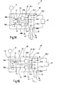
- Fig. 1A is shown in a schematic representation of a safety switching device and designated by the reference numeral 10.
- the safety switching device 10 comprises a schematically indicated safe evaluation and control unit 12.
- This evaluation and control unit 12 is constructed from known components, as they are also used in the aforementioned safety relay "PNOZ" of the applicant.
- the task of this evaluation and control unit is to reliably evaluate supplied switching signals, for example from an emergency stop switch 14, and to generate corresponding output signals.
- the evaluation and control unit 12 is constructed in the embodiment shown two channels, wherein the two channels are denoted by the reference numerals 16a and 16b. Of course, other embodiments of the evaluation and control unit 12 are possible. For a more detailed explanation of such an evaluation and control unit 12 is, for example, on the book “Machine Safety”, Winfried Gräf, Wegig-Verlag, 1997, reference is made.
- the safety switching device 10 further comprises per channel a control device (switching control device) 20A and 20B, each receiving a control signal from the corresponding evaluation and control unit 16a and 16b via lines 22.
- a control device switching control device
- the lines 22 may also be multi-core bus lines.
- the control device 20 generates depending on the supplied control signals from the evaluation and control unit 12 drive signals, the switching elements 24.1 to 24.4 are supplied.
- the Fig. 1A indicates that the drive means 20A generates two drive signals, which are supplied to the two switching elements 24.1 and 24.3.
- the drive device 20B also generates two drive signals, which, however, are supplied to the two switching elements 24.2 and 24.4.
- the two control signals generated by the control device 20A and 20B are the same in each case, so that in the normal operation of the safety switching device 10, the switching element pairs 24.1 and 24.3 or 24.2 and 24.4 have the same switching state.
- the total of four switching elements 24.1 to 24.4 are arranged so that two identical current paths 26.1 and 26.2 are formed.
- the two switching elements 24.1 and 24.2 connected in series, so that they form the first current path 26.1, while the other two switching elements 24.3 and 24.4 are also connected in series and form the second current path 26.2.
- From the illustration in Fig. 1A clearly shows that the two current paths 26.1, 26.2 are parallel to each other.
- the two current paths 26.1, 26.2 connect an input terminal 30 of the safety switching device 10 to an output terminal 33.
- the switching elements 24 are switched on, an ohmic connection is thus created between the input terminal 30 and the output terminal 33, whereby a corresponding current can flow over both current paths 26.
- the safety switching device 10 has a further output terminal 35 and a further input terminal 37. From the Fig. 1A It can be seen that there is an electrical connection between the input terminal 37 and the output terminal 35.
- a DC voltage source 41 is connected to the two input terminals 30, 37, which provides, for example, a voltage of 24 volts between the two terminals 30, 37, the input terminal 30 at a positive potential and the input terminal 37 at a reference potential, eg. 0 volts lies.
- the load to be switched by the safety switching device 10 is in Fig. 1A shown schematically and identified by the reference numeral 43.
- the load 43 is a load of high power, for example, valve terminals for pneumatic or hydraulic controls, or output modules of a PLC control, which requires a current> 8 amps.
- the load 43 is connected between the output terminals 33 and 35. It follows that when switched switching elements 24, a current flow from the DC voltage source 41 via the input terminal 30, the two current paths 26.1, 26.2, the output terminal 33, the load 43, the output terminal 35, and the input terminal 37 back to the DC voltage source 41 results.
- the evaluation and control unit 12 If, for example, the emergency stop switch 14 is actuated, the evaluation and control unit 12 generates control signals which are converted by the two drive devices 20A, 20B into corresponding drive signals. These drive signals cause switching elements 24 to be switched off in order to switch off the current paths 26.1, 26.2. Thus, the load 43 is disconnected from the DC power source 41.
- the breaking capacity of the switching elements is now tested by switching off the two switching elements in one current path for a short period of time while the switching elements in the other current path maintain their switching state.
- the short turn-off of the switching elements in a current path causes the potential between the two tested switching elements to change, provided that the switching elements are in order. This potential change can be the evaluation and control unit 12 recognize and evaluate accordingly. If, for example, the switching element 24.1 can no longer be opened in the first current path 26.1, the potential does not change during the short test phase, which is recognized by the evaluation and control unit 12 as an error. An immediate shutdown of the entire safety relay and thus the load 43 would be the result.
- Fig. 1A can still recognize connections shown in dashed lines, which extend from the two evaluation and control units 16A, B to the drive means 20A, B and from the readback lines to the evaluation and control units 16A, B. These connections serve to continue the two-channel structure of the safety relay; these connections allow each evaluation and control unit 16A, B, all four switching elements 24.1-24.4 to control and check.
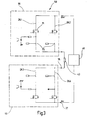
- Fig. 1B is a safety switching device 10 'is shown, with respect to the function of the already with reference to the Fig. 1A shown safety relay 10 corresponds. A detailed description should therefore be omitted here. Also the design of the safety relay 10 'does not differ from that of the safety switching device 10. The only difference is that the safety switching device 10' has been divided into two modules 50, 51.
- the module 50 which is referred to below as a safety switching module, comprises the drive means 20A, 20B and the switching elements 24, which are arranged in the two current paths 26.1, 26.2.
- the module 51 which is referred to below as the evaluation and control module, comprises the evaluation and control unit 12, the control signals to the input terminals 53 of the safety switching module 50 can be fed.
- the safety switching module 50 can be connected as an additional module for switching large currents to existing safety relays.
- Dashed lines show the individual function blocks, namely the two drive devices 20A, 20B and the switching elements 24.1 to 24.4.
- the drive means 20A comprises in the present embodiment, two drive units 61, 62 which generate depending on corresponding input signals in each case an output signal which is respectively supplied to an optocoupler 63 and 64 respectively.
- the outputs of the two optical couplers 63, 64 are connected in series and serve to control the switching element 24.1.
- the control input of the switching element 24.1 is connected via the outputs of the opto-couplers 63, 64 to a positive potential. If corresponding control signals are present at the inputs of the two optocouplers 63, 64, the outputs of the two optocouplers are connected to one another, so that then the switching element 24.1 receives a drive signal with a positive potential and closes on the basis thereof. This is the normal mode of operation of the safety switch module 50 to power the load 43.
- the switching element 24.1 is designed as a semiconductor switching element, preferably as a field effect transistor 71.
- the second switching element 24.2 in the same current path 26.1 as an electromechanical switching element, preferably designed as a relay 73.
- This relay 73 is controlled via corresponding drive units 61, 62. Since the relay 73 itself provides a galvanic isolation to the driver 20B, the use of optocouplers 63, 64 can be dispensed with.
- control of the field effect transistor 71 and the relay 73 is two-channel. Only if both drive units 61, 62 a corresponding Generate control signal, the switching element 24.1, 24.2 is closed.
- the evaluation and control unit 12 checks the breaking capacity of the switching elements 24 by briefly switching off the switching elements of a current path
- a signal between the two switching elements 24.1, 24.2 is tapped off via the line 45 and fed to an optocoupler 83.
- This optocoupler 83 generates a readback signal which is fed to the evaluation and control unit 12.
- This readback signal provides information on whether the FET 71 and the contact 73 are switched off during the test phase. Do both switching elements 71 and 73, the security is guaranteed; however, if they fail to do so, the FET 71 or contact 73 will be faulty, with the result that the entire safety switch module 50 must be turned off so that the load 43 is placed in the safe state.
- the structure of the second current path 26.2 corresponds exactly to that of the current path 26.1, so that it is possible to dispense with a repeated description at this point. For clarity, some elements have been combined to form a functional block, for example.
- the Abschaltgrin the FET 71 and the contact 24.4 is carried out by modulating a short turn-off on the drive signal. An appropriate readback signal is then generated via an optocoupler 83.
- the switching elements of a current path are diversified. This makes it possible to exclude faults in a current path due to the same causes.
- semiconductor switching elements or electromechanical switching elements can be used.
- FIG. 3 Another embodiment of a safety switching module is in Fig. 3 shown and designated by the reference numeral 50 '.
- safety switching module 50 is a two-pole version of a safety switching module. That is, the load 43 between two safety switch modules 50, as in Fig. 2 represented lies.
- the connection between the terminal 35 and the terminal 37 is thus not directly, but also via two current paths 26.3 and 26.4, which are constructed in an interchangeable arrangement to the two current paths 26.1 and 26.2.
- the operation corresponds to the safety switch module 50, as in Fig. 2 has been shown and described, so that can be dispensed with a repeated description.
- the advantage is that the load can be switched off safely even with a 24V short circuit.
Landscapes
- Engineering & Computer Science (AREA)
- General Engineering & Computer Science (AREA)
- Mechanical Engineering (AREA)
- Electronic Switches (AREA)
- Testing Electric Properties And Detecting Electric Faults (AREA)
- Keying Circuit Devices (AREA)
- Monitoring And Testing Of Exchanges (AREA)
Description
- Die vorliegende Erfindung betrifft ein Sicherheitsschaltmodul zum sicheren Abschalten einer elektrischen Last, mit einer ersten und einer zweiten Schaltsteuereinrichtung, einem ersten und einem in Reihe dazu angeordneten zweiten Schaltelement, die einen ersten Strompfad zur Versorgung der Last bilden, wobei das erste Schaltelement von der ersten Schaltsteuereinrichtung und das zweite Schaltelement von der zweiten Schaltsteuereinrichtung steuerbar ist, und einer Auswerte- und Steuereinheit zur Prüfung des Abschaltvermögens von zumindest einem Schaltelement.
- Solche Sicherheitsschaltmodule bzw. Sicherheitsschaltgeräte sind allgemein bekannt. So bietet die Anmelderin bspw. Sicherheitsschaltgeräte in unterschiedlichen Varianten unter dem Namen "PNOZ" an. In der Patentanmeldung
DE 100 11 211 der Anmelderin ist bspw. ein solches Sicherheitsschaltgerät offenbart. - Ferner ist aus
DE 37 32 079 C2 ein Verfahren und eine Vorrichtung bekannt, die einen überbrückungsstromkreis für mindestens einen mechanischen Schaltkontakt betreiben. - Allgemein werden derartige Sicherheitsschaltgeräte vor allem im industriellen Bereich verwendet, um elektrisch angetriebene Maschinen, wie bspw. eine Presse oder ein Fräswerkzeug, eine Ventilinsel für Pneumatik- oder Hydrauliksteuerungen oder Ausgangsmodule einer SPS, ein- und sicher auszuschalten. Sie dienen insbesondere in Verbindung mit einem mechanisch betätigbaren Not-Aus-Taster dazu, die Maschine in einer Notfallsituation schnell und sicher abzuschalten. Hierzu wird die Stromversorgung der abzuschaltenden Maschine über zwei in Reihe geschaltete Schaltelemente geführt. Sobald auch nur eines der beiden Schaltelemente öffnet, wird die Stromzuführung der Maschine unterbrochen.
- Um im Betrieb eines solchen Sicherheitsschaltgeräts eine Überprüfung des Schaltvermögens der Schaltelemente durchzuführen, ist eine Auswerte- und Steuereinheit vorgesehen, die die Schaltelemente kurzzeitig einzeln abschaltet und dabei das Ausgangssignal (Rücklesesignal) der Schaltelemente erfaßt und auswertet. Anhand dieser Auswertung kann die Auswerte- und Steuereinheit feststellen, ob jedes Schaltelement in der Lage ist, die elektrische Versorgung der Maschine, d.h. allgemein der elektrischen Last in einer Notfallsituation zu unterbrechen. Um die elektrische Last durch diesen Prüfvorgang nicht zu beeinflussen, wird das Schaltelement nur für eine sehr kurze Zeitdauer abgeschaltet, die für die Last nicht "sichtbar" ist.
- Aufgrund der Trägheit von elektromechanischen Schaltelementen ist dieser Prüfvorgang nur bei elektronischen Schaltelementen auf der Basis von Halbleiterbauelementen möglich. Übersteigt der von dem Schaltelement zu schaltende Strom jedoch einen bestimmten Wert (typischerweise etwa 8 Ampere) und handelt es sich bei der elektrischen Last nicht um einen reinen Ohmschen Verbraucher (kapazitive oder induktive Bestandteile), so ist der vorgenannte Prüfvorgang durch kurzes Abschalten der Schaltelemente nur mit großem zusätzlichen Bauteilaufwand möglich. Zum Auswerten des Ausgangssignals des Schaltelements müßte nämlich dann zunächst die Last entladen werden, um den Abschaltimpuls klein zu halten. Das kurzzeitige Entladen eines größeren Kondensators würde einen sehr großen Entladestrom erfordern. Um bspw. einen ImF-Kondensator in 200 µs um 25 V zu entladen, ist ein Entladestrom von 125 A erforderlich
- Vor diesem Hintergrund besteht die Aufgabe der vorliegenden Erfindung darin, ein Sicherheitsschaltmodul der vorgenannten Art vorzusehen, das auf einfache Weise eine Prüfung des Abschaltvermögens der Schaltelemente auch bei großen zu schaltenden Strömen und/oder kapazitiven oder induktiven Lasten ermöglicht.
- Diese Aufgabe wird bei dem Sicherheitsschaltmodul der vorgenannten Art dadurch gelöst, daß ein drittes und ein viertes Schaltelement vorgesehen sind, die in Reihe zueinander und parallel zu der Reihenschaltung aus erstem und zweitem Schaltelement angeordnet sind und einen zweiten Strompfad bilden, wobei das dritte Schaltelement von der ersten Schaltsteuereinrichtung und das vierte Schaltelement von der zweiten Schaltsteuereinrichtung steuerbar ist, und daß die Auswerte- und Steuereinheit die Prüfung beider Schaltelemente in abwechselnd einem der beiden Strompfade durchführt, so daß dann der andere der beiden Strompfade die Last versorgt.
- Das heißt mit anderen Worten, daß zusätzlich zu dem bisherigen Strompfad, der durch die beiden Schaltelemente stromlos geschaltet werden kann, ein weiterer Strompfad mit zwei weiteren Schaltelementen parallel geschaltet wird. Im normalen Betrieb wird die Last über, beide Strompfade mit elektrischer Energie versorgt. Während eines Prüfzyklus wird einer der beiden Strompfade auf sein Abschaltvermögen hin geprüft, während dann der andere Strompfad die elektrische Versorgung alleine übernimmt. Somit ist es möglich, weiterhin durch kurzes Abschalten der Schaltelemente eine Prüfung des Abschaltvermögens durch Rücklesen von Ausgangssignalen dieser Schaltelemente durchzuführen, ohne daß dies die Versorgung der elektrischen Last behindern würde. Folglich läßt sich mit einfachen Mitteln ein Sicherheitsschaltmodul zum sicheren Abschalten auch von großen Strömen aufbauen.
- Da der Abschaltimpuls an der Last nicht anliegt, sind längere Abschaltimpulse möglich. Das bedeutet, daß mit dem erfindungsgemäßen Aufbau neben Halbleiterbauelementen auch elektromechanische Schaltelemente getestet werden können, während die Last eingeschaltet ist.
- Ein weiterer Vorteil des erfindungsgemäßen Aufbaus ist auch darin zu sehen, daß die Versorgungssicherheit erhöht wird, da bei Ausfall eines Strompfads, bspw. aufgrund eines durchlegierten Halbleiter-Schaltelements bei entsprechender Ansteuerung, weiterhin eine sichere Versorgung der Last möglich ist.
- In einer vorteilhaften Weiterbildung der Erfindung ist das erste und das dritte Schaltelement als Halbleiter-Schaltelement ausgebildet. Vorzugsweise ist das zweite und das vierte Schaltelement als elektromechanisches Schaltelement, vorzugsweise als Relais ausgebildet.
- Diese Maßnahmen haben den Vorteil, daß bspw. die Relaiskontakte den Strom im. Normalbetrieb nicht zu schalten brauchen, da das Halbleiter-Schaltelement schneller schaltet und den Strom bereits abgeschaltet hat. Damit werden die Relaiskontakte geschont und die Lebensdauer wesentlich erhöht. Aufgrund der Verwendung diversitärer Schaltelemente (Halbleiter und Relais) lassen sich Fehler in beiden Schaltelementen durch gleiche Ursachen, bspw. durch einen energiereichen Störimpuls, ausschließen. Selbstverständlich ist es auch denkbar, alle vier Schaltelemente gleich als Halbleiter-Schaltelemente, als wechselstromschaltende Halbleiter-Schaltelemente, vorzugsweise Photo-MOS-Relais, oder als Relais auszubilden
- In einer vorteilhaften Weiterbildung ist die Schaltsteuereinrichtung zweikanalig ausgebildet.
- Diese Maßnahme hat den Vorteil, daß die Sicherheit des Sicherheitsschaltmoduls weiter erhöht wird.
- In einer vorteilhaften Weiterbildung ist die Auswerte- und Steuereinheit mit jedem der beiden Strompfade derart verbunden, daß sie ein Signal zwischen dem ersten und dem zweiten bzw. dem dritten und dem vierten Schaltelement auslesen kann.
- Diese Maßnahme hat den Vorteil, daß die Auswerte- und Steuereinheit das Abschaltvermögen beider Schaltelemente in dem jeweiligen Strompfad erfassen kann.
- In einer vorteilhaften Weiterbildung ist die Auswerte- und Steuereinheit derart ausgebildet, daß sie einen kurzen Ausschaltimpuls erzeugen und entweder dem ersten oder dem dritten Schaltelement zuführen kann, um dieses kurz auszuschalten. Vorzugsweise wird dieser Ausschaltimpuls dem von der Schaltsteuereinrichtung erzeugten Steuersignal aufmoduliert.
- Diese Maßnahmen haben den Vorteil, daß ein sehr einfacher Aufbau zur Prüfung des Abschaltvermögens möglich wird.
- Es versteht sich, daß die vorstehend genannten und die nachstehend noch zu erläuternden Merkmale nicht nur in der jeweils angegebenen Kombination, sondern auch in anderen Kombinationen oder in Alleinstellung verwendbar sind, ohne den Rahmen der vorliegenden durch die Ansprüche definierten Erfindung zu verlassen.
- Ausführungsbeispiele der Erfindung sind in der Zeichnung dargestellt und werden in der nachfolgenden Beschreibung näher erläutert. Es zeigen:
- Fig. 1A
- eine schematische Darstellung eines Sicherheitsschaltgeräts gemäß einer ersten Ausführungsform;
- Fig. 1B
- eine schematische Darstellung eines Sicherheitsschaltgeräts gemäß einer zweiten Ausführungsform;
- Fig. 2
- ein schematisches Schaltungsdiagramm des erfindungsgemäßen Sicherheitsschaltmoduls in einer einpoligen Ausführung; und
- Fig. 3
- ein schematisches Schaltungsdiagramm des erfindungsgemäßen Sicherheitsschaltmoduls in einer zweipoligen Ausführung.
- In
Fig. 1A ist in schematischer Darstellung ein Sicherheitsschaltgerät gezeigt und mit dem Bezugszeichen 10 gekennzeichnet. Das Sicherheitsschaltgerät 10 umfaßt eine schematisch angedeutete sichere Auswert- und Steuereinheit 12. Diese Auswert- und Steuereinheit 12 ist aus bekannten Bauelementen aufgebaut, wie sie auch in dem vorgenannten Sicherheitsschaltgerät "PNOZ" der Anmelderin verwendet werden. Die Aufgabe dieser Auswerte- und Steuereinheit besteht darin, zugeführte Schaltsignale, bspw. von einem Not-Aus-Schalter 14, sicher auszuwerten und entsprechende Ausgangssignale zu erzeugen. - Die Auswerte- und Steuereinheit 12 ist im gezeigten Ausführungsbeispiel zweikanalig aufgebaut, wobei die beiden Kanäle mit dem Bezugszeichen 16a und 16b gekennzeichnet sind. Selbstverständlich sind auch andere Ausgestaltungen der Auswerte- und Steuereinheit 12 möglich. Zur näheren Erläuterung einer solchen Auswerte- und Steuereinheit 12 wird bspw. auf das Buch "Maschinensicherheit", Winfried Gräf, Hüthig-Verlag, 1997, Bezug genommen.
- Das Sicherheitsschaltgerät 10 umfaßt ferner pro Kanal eine Ansteuereinrichtung (Schaltsteuereinrichtung) 20A bzw. 20B, die jeweils ein Steuersignal von der entsprechenden Auswerte- und Steuereinheit 16a bzw. 16b über Leitungen 22 empfangen. Obgleich in
Fig. 1A für die Leitungen 22 jeweils nur eine Linie dargestellt ist, kann es sich bei den Leitungen 22 auch um mehradrige Busleitungen handeln. - Die Ansteuereinrichtung 20 erzeugt abhängig von den zugeführten Steuersignalen von der Auswerte- und Steuereinheit 12 Ansteuersignale, die Schaltelementen 24.1 bis 24.4 zugeführt werden. Die
Fig. 1A läßt erkennen, daß die Ansteuereinrichtung 20A zwei Ansteuersignale erzeugt, die den beiden Schaltelementen 24.1 und 24.3 zugeführt werden. Die Ansteuereinrichtung 20B erzeugt ebenfalls zwei Ansteuersignale, die jedoch den beiden Schaltelementen 24.2 und 24.4 zugeführt werden. Die beiden von der Ansteuereinrichtung 20A bzw. 20B erzeugten Ansteuersignale sind jeweils gleich, so daß im normalen Betrieb des Sicherheitsschaltgeräts 10 die Schaltelementpaare 24.1 und 24.3 bzw. 24.2 und 24.4 den gleichen Schaltzustand haben. - Erfindungsgemäß sind die insgesamt vier Schaltelemente 24.1 bis 24.4 so angeordnet, daß zwei identische Strompfade 26.1 und 26.2 gebildet werden. Insbesondere sind die beiden Schaltelemente 24.1 und 24.2 in Reihe geschaltet, so daß sie den ersten Strompfad 26.1 bilden, während die anderen beiden Schaltelemente 24.3 und 24.4 ebenfalls in Reihe geschaltet sind und den zweiten Strompfad 26.2 bilden. Aus der Darstellung in
Fig. 1A ergibt sich deutlich, daß die beiden Strompfade 26.1, 26.2 parallel zueinander liegen. Die beiden Strompfade 26.1, 26.2 verbinden einen Eingangsanschluß 30 des Sicherheitsschaltgeräts 10 mit einem Ausgangsanschluß 33. Bei eingeschalteten Schaltelementen 24 wird somit eine ohmsche Verbindung zwischen dem Eingangsanschluß 30 und dem Ausgangsanschluß 33 geschaffen, wobei ein entsprechender Strom über beide Strompfade 26 fließen kann. - Neben dem Ausgangsanschluß 33 weist das Sicherheitsschaltgerät 10 einen weiteren Ausgangsanschluß 35 und einen weiteren Eingangsanschluß 37 auf. Aus der
Fig. 1A ist ersichtlich, daß zwischen dem Eingangsanschluß 37 und dem Ausgangsanschluß 35 eine elektrische Verbindung besteht. - Im Betrieb wird an die beiden Eingangsanschlüsse 30, 37 eine Gleichspannungsquelle 41 angeschlossen, die bspw. eine Spannung von 24 Volt zwischen den beiden Anschlüssen 30, 37 bereitstellt, wobei der Eingangsanschluß 30 auf einem positiven Potential und der Eingangsanschluß 37 auf einem Bezugspotential, bspw. 0 Volt liegt.
- Die von dem Sicherheitsschaltgerät 10 zu schaltende Last ist in
Fig. 1A schematisch dargestellt und mit dem Bezugszeichen 43 gekennzeichnet. Im vorliegenden Ausführungsbeispiel handelt es sich um eine Last hoher Leistung, bspw. Ventilinseln für Pneumatik- oder Hydrauliksteuerungen, oder Ausgangsmodule einer SPS-Steuerung, die einen Strom > 8 Ampere benötigt. Die Last 43 ist zwischen den Ausgangsanschlüssen 33 und 35 angeschlossen. Daraus ergibt sich, daß sich bei eingeschalteten Schaltelementen 24 ein Stromfluß von der Gleichspannungsquelle 41 über den Eingangsanschluß 30, die beiden Strompfade 26.1, 26.2, den Ausgangsanschluß 33, die Last 43, den Ausgangsanschluß 35, und den Eingangsanschluß 37 zurück zur Gleichspannungsquelle 41 ergibt. Wird nun bspw. der Not-Aus-Schalter 14 betätigt, erzeugt die Auswerte- und Steuereinheit 12 Steuersignale, die von den beiden Ansteuereinrichtungen 20A, 20B in entsprechende Ansteuersignale umgewandelt werden. Diese Ansteuersignale verursachen ein Ausschalten der Schaltelemente 24, um die beiden Strompfade 26.1, 26.2 stromlos zu schalten. Damit wird die Last 43 von der Gleichspannungsquelle 41 getrennt. - Bei derartigen Sicherheitsschaltgeräten 10 ist es erforderlich, das Abschaltvermögen der Schaltelemente 24 in regelmäßigen Abständen zu testen. Hierfür wird zwischen den beiden Schaltelementen 24.1 und 24.2 des ersten Strompfads 26.1 sowie zwischen den beiden Schaltelementen 24.3 und 24.4 des zweiten Strompfads 26.2 ein Signal abgegriffen und der Auswerte- und Steuereinheit 12 zugeführt. Dies ist in
Fig. 1A durch die beiden mit dem Bezugszeichen 45 gekennzeichneten Pfeile angedeutet. - Das Abschaltvermögen der Schaltelemente wird nun dadurch getestet, daß die beiden Schaltelemente in einem Strompfad für eine kurze Zeitdauer abgeschaltet werden, während die Schaltelemente in dem anderen Strompfad ihren Schaltzustand beibehalten. Das kurze Abschalten der Schaltelemente in einem Strompfad führt dazu, daß sich das Potential zwischen den beiden getesteten Schaltelementen verändert, sofern die Schaltelemente in Ordnung sind. Diese Potentialveränderung kann die Auswerte- und Steuereinheit 12 erkennen und entsprechend auswerten. Sollte sich bspw. das Schaltelement 24.1 im ersten Strompfad 26.1 nicht mehr öffnen lassen, so verändert sich das Potential während der kurzen Testphase nicht, was von der Auswerte- und Steuereinheit 12 als Fehler erkannt wird. Eine sofortige Abschaltung des gesamten Sicherheitsschaltgeräts und damit auch der Last 43 wäre die Folge.
- Dadurch, daß zwei Strompfade 26.1, 26.2 vorgesehen sind, von denen jeweils nur einer einem Test unterzogen wird, wird eine gleichbleibende Energieversorgung der Last 43 auch während der Testphase garantiert. Somit ist es mit diesem Sicherheitsschaltgerät 10 möglich, das Abschaltvermögen von Schaltelementen zu testen, obgleich sehr große Ströme fließen. Darüber hinaus spielt es keine Rolle, ob die Last 43 eine rein ohmsche Last oder bspw. eine kapazitive Last ist.
-
Fig. 1A läßt noch gestrichelt dargestellte Verbindungen erkennen, die von den beiden Auswerte- und Steuereinheiten 16A,B zu den Ansteuereinrichtungen 20A,B verlaufen und von den Rückleseleitungen zu den Auswerte- und Steuereinheiten 16A,B. Diese Verbindungen dienen dazu, die zweikanalige Struktur des Sicherheitsschaltgeräts fortzusetzen; diese Verbindungen ermöglichen es jeder Auswerte- und Steuereinheit 16A,B, alle vier Schaltelemente 24.1-24.4 anzusteuern und zu überprüfen. - In
Fig. 1B ist ein Sicherheitsschaltgerät 10' gezeigt, das hinsichtlich der Funktion dem bereits mit Bezug auf dieFig. 1A gezeigten Sicherheitsschaltgerät 10 entspricht. Auf eine nochmalige ausführliche Beschreibung soll deshalb an dieser Stelle verzichtet werden. Auch der konstruktive Aufbau des Sicherheitsschaltgeräts 10' unterscheidet sich nicht von dem des Sicherheitsschaltgeräts 10. Der einzige Unterschied besteht darin, daß das Sicherheitsschaltgerät 10' in zwei Module 50, 51 aufgeteilt wurde. Das Modul 50, das nachfolgend als Sicherheitsschaltmodul bezeichnet wird, umfaßt die Ansteuereinrichtungen 20A, 20B sowie die Schaltelemente 24, die in den beiden Strompfaden 26.1, 26.2 angeordnet sind. Das Modul 51, das nachfolgend als Auswerte- und Steuermodul bezeichnet wird, umfaßt die Auswerte- und Steuereinheit 12, deren Steuersignale Eingangsanschlüssen 53 des Sicherheitsschaltmoduls 50 zuführbar sind. Durch die Aufgliederung des Sicherheitsschaltgeräts 10' in zwei einzelne Module 50, 51 läßt sich die Flexibilität steigern. Insbesondere kann das Sicherheitsschaltmodul 50 als Zusatzmodul zum Schalten großer Ströme an bereits existierende Sicherheitsschaltgeräte angeschlossen werden. - Mit Bezug auf die
Fig. 2 soll nun nachfolgend eine konkrete bevorzugte Ausgestaltung des Sicherheitsschaltmoduls 50 gezeigt werden, wobei an dieser Stelle jedoch anzumerken ist, daß es sich hierbei um eine rein beispielhafte Schaltungsanordnung handelt. Zur Erzielung der mit Bezug auf dieFig. 1A beschriebenen Funktionsweise sind selbstverständlich auch andere Schaltungsanordnungen denkbar. - Zur Vereinfachung sind in
Fig. 2 für die gleichen Bauelemente gleiche Bezugszeichen angegeben, so daß auf eine nochmalige Beschreibung dieser Bauelemente verzichtet werden kann. - Mit gestrichelten Linien sind die einzelnen Funktionsblöcke, nämlich die beiden Ansteuereinrichtungen 20A, 20B sowie die Schaltelemente 24.1 bis 24.4 dargestellt.
- Die Ansteuereinrichtung 20A umfaßt im vorliegenden Ausführungsbeispiel zwei Ansteuereinheiten 61, 62, die abhängig von entsprechenden Eingangssignalen jeweils ein Ausgangssignal erzeugen, das jeweils einem Optokoppler 63 bzw. 64 zugeführt wird. Die Ausgänge der beiden Optokoppler 63, 64 sind in Reihe geschaltet und dienen dazu, das Schaltelement 24.1 anzusteuern. Hierzu wird der Steuereingang des Schaltelements 24.1 über die Ausgänge der Optokoppler 63, 64 an ein positives Potential gelegt. Liegen entsprechende Steuersignale an den Eingängen der beiden Optokoppler 63, 64 an, werden die Ausgänge der beiden Optokoppler miteinander verbunden, so daß dann das Schaltelement 24.1 ein Ansteuersignal mit positivem Potential empfängt und aufgrund dessen schließt. Dies ist der normale Betriebsmodus des Sicherheitsschaltmoduls 50, um die Last 43 mit Energie zu versorgen.
- Im vorliegenden Ausführungsbeispiel ist das Schaltelement 24.1 als Halbleiter-Schaltelement, vorzugsweise als Feldeffekttransistor 71 ausgebildet.
- Im Gegensatz dazu ist das zweite Schaltelement 24.2 im gleichen Strompfad 26.1 als elektromechanisches Schaltelement, vorzugsweise als Relais 73 ausgebildet. Dieses Relais 73 wird über entsprechende Ansteuereinheiten 61, 62 gesteuert. Da das Relais 73 selbst eine galvanische Trennung zu der Ansteuereinrichtung 20B schafft, kann auf den Einsatz von Optokopplern 63, 64 verzichtet werden.
- In beiden Fällen ist jedoch anzumerken, daß die Ansteuerung des Feldeffekttransistors 71 bzw. des Relais 73 zweikanalig erfolgt. Nur wenn beide Ansteuereinheiten 61, 62 ein entsprechendes Ansteuersignal erzeugen, wird das Schaltelement 24.1, 24.2 geschlossen.
- Die Auswerte- und Steuereinheit 12 prüft das Abschaltvermögen der Schaltelemente 24 durch kurzzeitiges Abschalten der Schaltelemente eines Strompfades
- Zur Prüfung des Abschaltvermögens des FET 71 und des Kontakts 73 wird über die Leitung 45 ein Signal zwischen den beiden Schaltelementen 24.1, 24.2 abgegriffen und einem Optokoppler 83 zugeführt. Dieser Optokoppler 83 erzeugt ein Rücklesesignal, das der Auswerte- und Steuereinheit 12 zugeführt wird. Dieses Rücklesesignal gibt Aufschluß darüber, ob während der Testphase der FET 71 und der Kontakt 73 abschaltet. Tun dies beide Schaltelemente 71 und 73, ist die Sicherheit gewährleistet; tun sie dies jedoch nicht, ist der FET 71 oder der Kontakt 73 fehlerhaft mit der Folge, daß das gesamte Sicherheitsschaltmodul 50 abgeschaltet werden muß, so daß die Last 43 in den sicheren Zustand gebracht wird.
- Der Aufbau des zweiten Strompfads 26.2 entspricht exakt demjenigen des Strompfads 26.1, so daß auf eine nochmalige Beschreibung an dieser Stelle verzichtet werden kann. Der Übersichtlichkeit wegen sind einige Elemente zu einem Funktionsblock zusammengefaßt worden, bspw. die beiden Ansteuereinheiten 61, 62 und der Taktgenerator 81. Auch im zweiten Strompfad 26.2 wird das Abschaltvermögen des FET 71 und des Kontakts 24.4 durch Aufmodulieren eines kurzen Abschaltimpulses auf das Ansteuersignal durchgeführt. Über einen Optokoppler 83 wird dann ein entsprechendes Rücklesesignal erzeugt.
- Wesentlich an der Durchführung der Tests der Schaltelemente ist, daß immer nur ein Strompfad getestet wird, so daß der jeweils andere Strompfad eine entsprechende ununterbrochene Energieversorgung der Last 43 auch während der Testphase garantieren kann.
- In dem in
Fig. 2 gezeigten Ausführungsbeispiel sind die Schaltelemente eines Strompfads diversitär ausgebildet. Damit sind Fehler in einem Strompfad aufgrund gleicher Ursachen ausschließbar. Selbstverständlich können neben dieser bevorzugten Ausführungsform in einem Strompfad auch gleiche Schaltelemente, insbesondere Halbleiter-Schaltelemente oder elektromechanische Schaltelemente eingesetzt werden. - Ein weiteres Ausführungsbeispiel eines Sicherheitsschaltmoduls ist in
Fig. 3 gezeigt und mit dem Bezugszeichen 50' gekennzeichnet. Der Unterschied zu dem inFig. 2 gezeigten Sicherheitsschaltmodul 50 besteht darin, daß es sich um eine zweipolige Ausführung eines Sicherheitsschaltmoduls handelt. D.h., daß die Last 43 zwischen zwei Sicherheitsschaltmodulen 50, wie inFig. 2 dargestellt, liegt. Die Verbindung zwischen dem Anschluß 35 und dem Anschluß 37 erfolgt somit nicht direkt, sondern ebenfalls über zwei Strompfade 26.3 und 26.4, die in vertauschter Anordnung zu den beiden Strompfaden 26.1 und 26.2 aufgebaut sind. Die Funktionsweise entspricht jedoch dem Sicherheitsschaltmodul 50, wie es inFig. 2 gezeigt und beschrieben wurde, so daß auf eine nochmalige Beschreibung verzichtet werden kann. - Der Vorteil ist, daß die Last auch bei einem 24V-Kurzschluß noch sicher abgeschaltet werden kann.
- Zusammenfassend ist also festzustellen, daß das erfindungsgemäße Vorsehen zweier Strompfade, die abwechselnd getestet werden, auch ein Schalten hoher Ströme zuläßt, ohne auf eine Prüfung des Abschaltvermögens der Schaltelemente verzichten zu müssen oder hierfür komplizierte Prüfschaltungen schaffen zu müssen, die eventuell auf die jeweilige Last angepaßt werden müssen.
- Durch die erfindungsgemäße Schaltungsanordnung sind Unterbrechungen der Schaltelemente möglich, die länger dauern als die Abschaltreaktionszeit der Last. Damit ist auch der Test von Relais während des Betriebs möglich.
Claims (10)
- Sicherheitsschaltmodul zum sicheren Abschalten einer elektrischen Last (43), mit einer ersten und einer zweiten Schaltsteuereinrichtung (20A, 20B), einem ersten und einem in Reihe dazu angeordneten zweiten Schaltelement (24.1, 24.2), die einen ersten Strompfad (26.1) zur Versorgung der Last bilden, wobei das erste Schaltelement (24.1) von der ersten Schaltsteuereinrichtung (20A) und das zweite Schaltelement (24.2) von der zweiten Schaltsteuereinrichtung (20B) steuerbar ist, und mit einer Auswerte- und Steuereinrichtung (12) zur Prüfung des Abschaltvermögens von zumindest einem Schaltelement, dadurch gekennzeichnet, daß ein drittes und ein viertes Schaltelement (24.3, 24.4) vorgesehen sind, die in Reihe zueinander und parallel zu der Reihenschaltung aus erstem und zweitem Schaltelement (24.1, 24.2) angeordnet sind und einen zweiten Strompfad (26.2) bilden, wobei das dritte Schaltelement (24.3) von der ersten Schaltsteuereinrichtung (20A) und das vierte Schaltelement (24.4) von der zweiten Schaltsteuereinrichtung (20B) steuerbar ist, und daß die Auswerte- und Steuereinrichtung (12) die Prüfung der Schaltelemente (24) in abwechselnd einem der beiden Strompfade (26.1, 26.2) durchführt, so daß der andere der beiden Strompfade (26.2, 26.1) die Last (43) versorgt.
- Sicherheitsschaltmodul nach Anspruch 1, dadurch gekennzeichnet, daß das erste und das dritte Schaltelement (24.1, 24.3) als Halbleiter-Schaltelemente (71) ausgebildet sind.
- Sicherheitsschaltmodul nach Anspruch 1 oder 2, dadurch gekennzeichnet, daß das zweite und das vierte Schaltelement (24.2, 24.4) als elektromechanisches Schaltelement (73), vorzugsweise als Relais ausgebildet sind.
- Sicherheitsschaltmodul nach einem der vorhergehenden Ansprüche, dadurch gekennzeichnet, daß die Schaltsteuereinrichtungen (20A, 20B, 61, 62) zweikanalig ausgebildet sind.
- Sicherheitsschaltmodul nach einem der vorhergehenden Ansprüche, dadurch gekennzeichnet, daß die Strompfade auf einer Seite mit einer Versorgungsspannung und auf der anderen Seite mit der Last verbunden sind.
- Sicherheitsschaltmodul nach einem der vorhergehenden Ansprüche, dadurch gekennzeichnet, daß die Auswerte- und Steuereinrichtung (12, 83) mit jedem der beiden Strompfade (26.1, 26.2) zwischen dem ersten und dem zweiten (24.1, 24.2) bzw. dem dritten und dem vierten Schaltelement (24.3, 24.4) verbunden ist.
- Sicherheitsmodul nach einem der vorhergehenden Ansprüche, dadurch gekennzeichnet, daß die Auswerte- und Steuereinrichtung einen kurzen Ausschaltimpuls erzeugt und entweder dem ersten und dem zweiten Schaltelement (24.1, 24.2) oder dem dritten und vierten Schaltelement (24.3, 24.4) zuführt, um diese kurz auszuschalten.
- Sicherheitsmodul nach Anspruch 6, dadurch gekennzeichnet, daß der Ausschaltimpuls dem Signal der Schaltsteuereinrichtung aufmoduliert wird.
- Sicherheitsmodul nach einem der vorhergehenden Ansprüche, dadurch gekennzeichnet, daß die Schaltelemente (24.1 - 24.4) elektromechanische Schaltelemente, vorzugsweise Relais, sind.
- Sicherheitsmodul nach einem der Ansprüche 1 bis 7, dadurch gekennzeichnet, daß die Schaltelemente (24.1 - 24.4) Halbleiter-Schaltelemente sind.
Applications Claiming Priority (3)
| Application Number | Priority Date | Filing Date | Title |
|---|---|---|---|
| DE10127233A DE10127233C1 (de) | 2001-05-22 | 2001-05-22 | Sicherheitsschaltmodul und Verfahren zur Prüfung des Abschaltvermögens eines Schaltelements in einem Sicherheitsschaltmodul |
| DE10127233 | 2001-05-22 | ||
| PCT/EP2002/002840 WO2002095282A2 (de) | 2001-05-22 | 2002-03-14 | Sicherheitsschaltmodul und verfahren zur prüfung des abschaltvermögens eines schaltelements in einem sicherheitsschaltmodul |
Publications (2)
| Publication Number | Publication Date |
|---|---|
| EP1389284A2 EP1389284A2 (de) | 2004-02-18 |
| EP1389284B1 true EP1389284B1 (de) | 2008-07-30 |
Family
ID=7687234
Family Applications (1)
| Application Number | Title | Priority Date | Filing Date |
|---|---|---|---|
| EP02716833A Expired - Lifetime EP1389284B1 (de) | 2001-05-22 | 2002-03-14 | Sicherheitsschaltmodul zur prüfung des abschaltvermögens eines schaltelements in einem sicherheitsschaltmodul |
Country Status (8)
| Country | Link |
|---|---|
| US (1) | US7187091B2 (de) |
| EP (1) | EP1389284B1 (de) |
| JP (1) | JP4191494B2 (de) |
| AT (1) | ATE403106T1 (de) |
| AU (1) | AU2002247759A1 (de) |
| DE (1) | DE10127233C1 (de) |
| ES (1) | ES2311596T3 (de) |
| WO (1) | WO2002095282A2 (de) |
Cited By (1)
| Publication number | Priority date | Publication date | Assignee | Title |
|---|---|---|---|---|
| DE202015103339U1 (de) | 2015-06-25 | 2016-09-30 | Weidmüller Interface GmbH & Co. KG | Schaltungsanordnung für einen sicheren digitalen Schaltausgang |
Families Citing this family (39)
| Publication number | Priority date | Publication date | Assignee | Title |
|---|---|---|---|---|
| DE10216226A1 (de) * | 2002-04-08 | 2003-10-30 | Pilz Gmbh & Co | Vorrichtung zum fehlersicheren Abschalten eines elektrischen Verbrauchers, insbesondere in industriellen Produktionsanlagen |
| US7193379B2 (en) | 2003-10-20 | 2007-03-20 | Wabtec Holding Corp. | Electronic circuit arrangement for switching an electrical load in a fail safe manner |
| EP1738383B2 (de) * | 2004-04-19 | 2023-01-11 | Pilz GmbH & Co. KG | Meldegerät für eine sicherheitsschaltung |
| GB2429347B (en) * | 2005-04-01 | 2007-08-08 | Westinghouse Airbrake Technolo | Electronic circuit arrangement for switching an electrical load in a fail safe manner |
| CN102013666A (zh) | 2005-08-02 | 2011-04-13 | 菲尼克斯电气公司 | 三相功率放大器及用于其的换向开关装置 |
| DE102006061476B3 (de) * | 2006-12-23 | 2008-06-26 | Berger Lahr Gmbh & Co. Kg | Elektrische Steuerung |
| US20090050453A1 (en) * | 2007-08-23 | 2009-02-26 | Honeywell International Inc. | Explosion proof safety switch apparatus |
| DE102009017275B4 (de) | 2009-04-11 | 2014-01-09 | Festo Ag & Co. Kg | Vorrichtung zur Überwachung der Schaltfähigkeit wenigstens eines zur Schaltung eines elektrischen Verbrauchers dienenden Halbleiterschalters |
| DE102010004524B4 (de) * | 2010-01-14 | 2017-01-19 | Festo Ag & Co. Kg | Vorrichtung zur elektrischen Stromkreisüberwachung |
| DE102010007784A1 (de) | 2010-02-12 | 2011-08-18 | FESTO AG & Co. KG, 73734 | Vorrichtung zur elektrischen Stromkreisüberwachung |
| DE102011086756A1 (de) * | 2010-11-23 | 2012-05-24 | Continental Teves Ag & Co. Ohg | Verfahren zur Fehlererkennung eines Bedienschalters zur Auslösung einer Fahrzeugfunktion eines Fahrzeuges sowie Bedienschalter zur Durchführung des Verfahrens |
| EP2461342B1 (de) * | 2010-12-06 | 2015-01-28 | Siemens Aktiengesellschaft | Fehlersicheres Schaltmodul |
| GB2486493B (en) * | 2010-12-17 | 2016-06-15 | Ge Aviat Systems Ltd | Switching circuits and methods of testing |
| JP5546524B2 (ja) * | 2011-12-06 | 2014-07-09 | オムロンオートモーティブエレクトロニクス株式会社 | 車両のスタータモータ駆動回路 |
| US8836338B2 (en) | 2011-12-16 | 2014-09-16 | Ge Aviation Systems Limited | Switching circuits and methods of testing thereof |
| US9628065B2 (en) * | 2012-10-05 | 2017-04-18 | Fisher-Rosemount Systems, Inc. | Safety instrumented process control apparatus and methods |
| DE102012111070B4 (de) * | 2012-11-16 | 2015-02-19 | Phoenix Contact Gmbh & Co. Kg | Sicherheitsbezogene Vorrichtung zum sicheren Schalten einer elektrischen Last |
| EP2800118B1 (de) * | 2013-04-29 | 2016-12-28 | Rockwell Automation Germany GmbH & Co. KG | Automatische Erkennung einer Schutzsperrvorrichtung |
| DE202013007990U1 (de) | 2013-09-11 | 2013-10-09 | Bürkert Werke GmbH | Elektromagnetischer Stellenantrieb für ein Magnetventil, Ventilinsel mit zumindest einem Magnetventil und Modulanordnung |
| ITFI20130242A1 (it) * | 2013-10-16 | 2015-04-17 | Microtest S R L | Un miglioramento dispositivo a relay per apertura e chiusura di un circuito |
| DE102013112488A1 (de) * | 2013-11-13 | 2015-05-13 | Pilz Gmbh & Co. Kg | Sicherheitssteuerung mit konfigurierbaren Eingängen |
| CN105229885B (zh) | 2014-03-17 | 2017-06-09 | 三菱电机株式会社 | 电力供给控制装置及可编程逻辑控制器 |
| DE102015203252A1 (de) * | 2015-02-24 | 2016-08-25 | Zf Friedrichshafen Ag | Sicherheitsvorrichtung und Verfahren zum Überführen eines Aktorsystems in einen sicheren Zustand, Aktorsystem und Verfahren zum Betreiben eines Aktorsystems |
| DE102015104211A1 (de) | 2015-03-20 | 2016-09-22 | Pilz Gmbh & Co. Kg | Sicherheitsschaltgerät zum fehlersicheren Abschalten einer elektrischen Last |
| US10245802B2 (en) * | 2015-07-28 | 2019-04-02 | Toyota Motor Engineering & Manufacturing North America, Inc. | Die compatibility adaptor for machine press communication |
| DE102015222990A1 (de) | 2015-11-20 | 2017-05-24 | Zf Friedrichshafen Ag | Sichere Steuerung eines Verbrauchers |
| US10360790B2 (en) | 2016-04-22 | 2019-07-23 | Banner Engineering Corp. | Safety touch button system having an intercommunications link |
| DE102016109915A1 (de) * | 2016-05-30 | 2017-11-30 | Pilz Gmbh & Co. Kg | Vorrichtung zum fehlersicheren Abschalten eines Verbrauchers |
| DE202016006083U1 (de) * | 2016-09-30 | 2018-01-03 | WAGO Verwaltungsgesellschaft mit beschränkter Haftung | Parallel geschaltete Halbleiterschalter zur redundanten Stromversorgung und Unterbrechung |
| DE102016122370A1 (de) * | 2016-11-21 | 2018-05-24 | Pilz Gmbh & Co. Kg | Not-Befehlsgerät und Sicherheitseinrichtung mit einem Not-Befehlsgerät |
| EP3462471B1 (de) * | 2017-09-29 | 2022-04-13 | Rockwell Automation Switzerland GmbH | Schutzschalter |
| DE102018200120A1 (de) * | 2018-01-05 | 2019-07-11 | Kuka Deutschland Gmbh | Sicherheitssteuerung mit wenigstens einem Halbleiterschaltkontakt |
| DE102018114781A1 (de) * | 2018-06-20 | 2019-12-24 | Pilz Gmbh & Co. Kg | Schaltungsanordnung zum Schalten einer elektrischen Last und Verfahren zur Überprüfung eines Status eines Sicherheitsausgangs einer Schaltungsanordnung |
| PL237078B1 (pl) * | 2018-12-18 | 2021-03-08 | Mdj Electronic Spolka Z Ograniczona Odpowiedzialnoscia | Iskrobezpieczny elektroniczny przekaźnik bezpieczeństwa |
| US12313684B2 (en) | 2019-07-01 | 2025-05-27 | Gillig Llc | High-voltage system test measurement systems and methods |
| US12444556B2 (en) | 2019-07-03 | 2025-10-14 | Gillig Llc | High-voltage system test measurement systems and methods |
| SE544824C2 (en) * | 2021-04-16 | 2022-12-06 | Bombardier Transp Gmbh | Digital output module |
| MX2023013166A (es) | 2021-05-07 | 2024-08-27 | Redkik Oy | Evaluación de la probabilidad de riesgo para las operaciones de envío de carga y sus métodos de uso. |
| DE102021126553A1 (de) | 2021-10-13 | 2023-04-13 | Ebm-Papst Landshut Gmbh | Verfahren zur sicherheitsgerichteten Steuerung |
Family Cites Families (9)
| Publication number | Priority date | Publication date | Assignee | Title |
|---|---|---|---|---|
| DE3732079A1 (de) * | 1987-09-24 | 1989-04-06 | Vdo Schindling | Verfahren und vorrichtung zum betrieb eines ueberbrueckungsstromkreises fuer mindestens einen mechanischen schaltkontakt innerhalb einer eine sicherheitsfunktion ausuebenden schaltungsanordnung |
| DE4224620C1 (de) * | 1992-07-25 | 1994-03-17 | Pilz Gmbh & Co | Drehzahlüberwachungsgerät für Drehfeldmaschinen |
| SE470530B (sv) * | 1992-11-16 | 1994-07-04 | Ericsson Telefon Ab L M | Strömbegränsare |
| EP0775332B1 (de) * | 1995-03-11 | 2000-05-10 | Leuze electronic GmbH + Co. | Sicherheitsschalteranordnung |
| DE69523752T2 (de) * | 1995-08-31 | 2002-08-29 | St Microelectronics Srl | Verfahren und Schaltung zur pulsbreitenmodulierten Steuerung einer Brücke und eines Plattenantriebs und unter Verwendung derselben |
| US5933304A (en) * | 1998-04-28 | 1999-08-03 | Carlingswitch, Inc. | Apparatus and method of interrupting current for reductions in arcing of the switch contacts |
| FR2791144B1 (fr) * | 1999-03-19 | 2001-11-30 | Sextant Avionique | Dispositif de surveillance de la circulation d'un courant sensiblement continu dans une charge et procede pour la mise en oeuvre de ce dispositif |
| DE19941022A1 (de) * | 1999-08-28 | 2001-03-01 | Gestra Gmbh | Steuergerät für wärmetechnische Anlagen |
| DE10011211B4 (de) * | 2000-03-08 | 2004-08-05 | Pilz Gmbh & Co. | Sicherheitsschaltgerät und Sicherheitsschaltgeräte-System |
-
2001
- 2001-05-22 DE DE10127233A patent/DE10127233C1/de not_active Expired - Fee Related
-
2002
- 2002-03-14 WO PCT/EP2002/002840 patent/WO2002095282A2/de not_active Ceased
- 2002-03-14 AU AU2002247759A patent/AU2002247759A1/en not_active Abandoned
- 2002-03-14 JP JP2002591715A patent/JP4191494B2/ja not_active Expired - Fee Related
- 2002-03-14 EP EP02716833A patent/EP1389284B1/de not_active Expired - Lifetime
- 2002-03-14 AT AT02716833T patent/ATE403106T1/de not_active IP Right Cessation
- 2002-03-14 ES ES02716833T patent/ES2311596T3/es not_active Expired - Lifetime
-
2003
- 2003-11-20 US US10/717,785 patent/US7187091B2/en not_active Expired - Lifetime
Cited By (2)
| Publication number | Priority date | Publication date | Assignee | Title |
|---|---|---|---|---|
| DE202015103339U1 (de) | 2015-06-25 | 2016-09-30 | Weidmüller Interface GmbH & Co. KG | Schaltungsanordnung für einen sicheren digitalen Schaltausgang |
| WO2016207382A2 (de) | 2015-06-25 | 2016-12-29 | Weidmüller Interface GmbH & Co. KG | Schaltungsanordnung für einen sicheren digitalen schaltausgang sowie ausgangsmodul mit und prüfverfahren für eine derartige schaltungsanordnung |
Also Published As
| Publication number | Publication date |
|---|---|
| JP2005501200A (ja) | 2005-01-13 |
| AU2002247759A1 (en) | 2002-12-03 |
| WO2002095282A2 (de) | 2002-11-28 |
| JP4191494B2 (ja) | 2008-12-03 |
| WO2002095282A3 (de) | 2003-11-20 |
| ES2311596T3 (es) | 2009-02-16 |
| DE10127233C1 (de) | 2002-11-28 |
| ATE403106T1 (de) | 2008-08-15 |
| US7187091B2 (en) | 2007-03-06 |
| US20040160131A1 (en) | 2004-08-19 |
| EP1389284A2 (de) | 2004-02-18 |
Similar Documents
| Publication | Publication Date | Title |
|---|---|---|
| EP1389284B1 (de) | Sicherheitsschaltmodul zur prüfung des abschaltvermögens eines schaltelements in einem sicherheitsschaltmodul | |
| EP1262021B2 (de) | Sicherheitsschaltgerät und sicherheitsschaltgeräte-system | |
| EP1269274B2 (de) | Sicherheitsschaltgerät und verfahren zur einstellung eines betriebsmodus eines sicherheitsschaltgeräts | |
| EP1493064B2 (de) | Vorrichtung zum fehlersicheren abschalten eines elektrischen verbrauchers, insbesondere in industriellen produktionsanlagen | |
| EP2980659B1 (de) | Vorrichtung und Verfahren zum Überwachen und Schalten eines Lastkreises | |
| EP1861860A1 (de) | Sicherheitsschaltvorrichtung zum sicheren abschalten eines elektrischen verbrauchers | |
| WO2010012536A1 (de) | Sicherheitsschaltanordnung zur ausgabe eines schaltsignals | |
| EP1869687B1 (de) | Sicherheitsschaltvorrichtung zum sicheren abschalten eines elektrischen verbrauchers | |
| EP1873916A2 (de) | Sichere Ausgangschaltung mit einem einkanaligen Perpherieanschluss für den Ausgang eines Bus-Teilnehmers | |
| DE112014002062B4 (de) | Stromzufuhrsteuerungsvorrichtung und speicherprogrammierbare Steuerung | |
| DE1537379C3 (de) | Sicherheitsschaltung zum Durchführen logischer Verknüpfungen für binäre Schaltvariable und deren antivalente Schaltvariable | |
| DE10149234B4 (de) | Sicherungsgeschützter Nebenschlußregler und Verfahren zum Schützen eines Nebenschußreglers | |
| DE2651314B1 (de) | Sicherheits-Ausgabeschaltung fuer eine Binaersignale abgebende Datenverarbeitungsanlage | |
| DE10045651B4 (de) | Sicherheitsschaltgerät | |
| DE10307997B4 (de) | Antriebssteuereinrichtung für einen selbstgeführten Stromrichter | |
| DE10109864A1 (de) | Sicherheitsschaltvorrichtung | |
| EP2876509B1 (de) | Sicherheitssteuerung | |
| DE102014008906A1 (de) | Elektronisches Relais | |
| EP1134715B1 (de) | Lampenschaltung eines Signalgebers einer Verkehrssignalanlage | |
| EP3208922A1 (de) | Modulselbstdiagnose in einem modularen mehrzellen stromrichter | |
| DE2143375B1 (de) | Elektronisches Speicherglied für digitale Datenverarbeitungsanlagen mit hoher Fehlersicherheit, insbesondere für das Eisenbahnsicherungswesen | |
| DE1463398C (de) | Anordnung zur Signalumsetzung und Fehlerüberwachung fur zweikanalige Steue rungen | |
| CH600424A5 (en) | Amplifier cct. for binary signals in railway signalling | |
| DE2442874A1 (de) | Verstaerkerschaltung fuer binaersignale | |
| EP2337054A2 (de) | Sicherheitsrelaisschaltung |
Legal Events
| Date | Code | Title | Description |
|---|---|---|---|
| PUAI | Public reference made under article 153(3) epc to a published international application that has entered the european phase |
Free format text: ORIGINAL CODE: 0009012 |
|
| 17P | Request for examination filed |
Effective date: 20031125 |
|
| AK | Designated contracting states |
Kind code of ref document: A2 Designated state(s): AT BE CH CY DE DK ES FI FR GB GR IE IT LI LU MC NL PT SE TR |
|
| AX | Request for extension of the european patent |
Extension state: AL LT LV MK RO SI |
|
| 17Q | First examination report despatched |
Effective date: 20050215 |
|
| GRAP | Despatch of communication of intention to grant a patent |
Free format text: ORIGINAL CODE: EPIDOSNIGR1 |
|
| RTI1 | Title (correction) |
Free format text: SAFETY SWITCHING MODULE FOR TESTING THE SWITCHING-OFF ABILITY OF A SWITCHING ELEMENT IN A SAFETY SWITCHING MODULE |
|
| RAP1 | Party data changed (applicant data changed or rights of an application transferred) |
Owner name: PILZ GMBH & CO. |
|
| GRAS | Grant fee paid |
Free format text: ORIGINAL CODE: EPIDOSNIGR3 |
|
| RBV | Designated contracting states (corrected) |
Designated state(s): AT BE CH CY DK ES FI FR GB GR IE IT LI LU MC NL PT SE TR |
|
| GRAA | (expected) grant |
Free format text: ORIGINAL CODE: 0009210 |
|
| AK | Designated contracting states |
Kind code of ref document: B1 Designated state(s): AT BE CH CY DK ES FI FR GB GR IE IT LI LU MC NL PT SE TR |
|
| REG | Reference to a national code |
Ref country code: GB Ref legal event code: FG4D Free format text: NOT ENGLISH |
|
| REG | Reference to a national code |
Ref country code: CH Ref legal event code: NV Representative=s name: TROESCH SCHEIDEGGER WERNER AG Ref country code: CH Ref legal event code: EP |
|
| REG | Reference to a national code |
Ref country code: DE Ref legal event code: 8566 |
|
| REG | Reference to a national code |
Ref country code: IE Ref legal event code: FG4D Free format text: LANGUAGE OF EP DOCUMENT: GERMAN |
|
| REG | Reference to a national code |
Ref country code: SE Ref legal event code: TRGR |
|
| PG25 | Lapsed in a contracting state [announced via postgrant information from national office to epo] |
Ref country code: PT Free format text: LAPSE BECAUSE OF FAILURE TO SUBMIT A TRANSLATION OF THE DESCRIPTION OR TO PAY THE FEE WITHIN THE PRESCRIBED TIME-LIMIT Effective date: 20081230 Ref country code: NL Free format text: LAPSE BECAUSE OF FAILURE TO SUBMIT A TRANSLATION OF THE DESCRIPTION OR TO PAY THE FEE WITHIN THE PRESCRIBED TIME-LIMIT Effective date: 20080730 |
|
| REG | Reference to a national code |
Ref country code: ES Ref legal event code: FG2A Ref document number: 2311596 Country of ref document: ES Kind code of ref document: T3 |
|
| PG25 | Lapsed in a contracting state [announced via postgrant information from national office to epo] |
Ref country code: FI Free format text: LAPSE BECAUSE OF FAILURE TO SUBMIT A TRANSLATION OF THE DESCRIPTION OR TO PAY THE FEE WITHIN THE PRESCRIBED TIME-LIMIT Effective date: 20080730 |
|
| REG | Reference to a national code |
Ref country code: IE Ref legal event code: FD4D |
|
| PG25 | Lapsed in a contracting state [announced via postgrant information from national office to epo] |
Ref country code: IE Free format text: LAPSE BECAUSE OF FAILURE TO SUBMIT A TRANSLATION OF THE DESCRIPTION OR TO PAY THE FEE WITHIN THE PRESCRIBED TIME-LIMIT Effective date: 20080730 Ref country code: DK Free format text: LAPSE BECAUSE OF FAILURE TO SUBMIT A TRANSLATION OF THE DESCRIPTION OR TO PAY THE FEE WITHIN THE PRESCRIBED TIME-LIMIT Effective date: 20080730 |
|
| PGFP | Annual fee paid to national office [announced via postgrant information from national office to epo] |
Ref country code: ES Payment date: 20090324 Year of fee payment: 8 |
|
| PLBI | Opposition filed |
Free format text: ORIGINAL CODE: 0009260 |
|
| PLAX | Notice of opposition and request to file observation + time limit sent |
Free format text: ORIGINAL CODE: EPIDOSNOBS2 |
|
| 26 | Opposition filed |
Opponent name: EUCHNER GMBH + CO. KG Effective date: 20090429 |
|
| PGFP | Annual fee paid to national office [announced via postgrant information from national office to epo] |
Ref country code: GB Payment date: 20090325 Year of fee payment: 8 |
|
| PGFP | Annual fee paid to national office [announced via postgrant information from national office to epo] |
Ref country code: SE Payment date: 20090312 Year of fee payment: 8 |
|
| BERE | Be: lapsed |
Owner name: PILZ G.M.B.H. & CO. Effective date: 20090331 |
|
| PLAF | Information modified related to communication of a notice of opposition and request to file observations + time limit |
Free format text: ORIGINAL CODE: EPIDOSCOBS2 |
|
| PG25 | Lapsed in a contracting state [announced via postgrant information from national office to epo] |
Ref country code: MC Free format text: LAPSE BECAUSE OF NON-PAYMENT OF DUE FEES Effective date: 20090331 |
|
| PLBB | Reply of patent proprietor to notice(s) of opposition received |
Free format text: ORIGINAL CODE: EPIDOSNOBS3 |
|
| PG25 | Lapsed in a contracting state [announced via postgrant information from national office to epo] |
Ref country code: BE Free format text: LAPSE BECAUSE OF NON-PAYMENT OF DUE FEES Effective date: 20090331 |
|
| PG25 | Lapsed in a contracting state [announced via postgrant information from national office to epo] |
Ref country code: AT Free format text: LAPSE BECAUSE OF NON-PAYMENT OF DUE FEES Effective date: 20090314 |
|
| PG25 | Lapsed in a contracting state [announced via postgrant information from national office to epo] |
Ref country code: GR Free format text: LAPSE BECAUSE OF FAILURE TO SUBMIT A TRANSLATION OF THE DESCRIPTION OR TO PAY THE FEE WITHIN THE PRESCRIBED TIME-LIMIT Effective date: 20081031 |
|
| EUG | Se: european patent has lapsed | ||
| GBPC | Gb: european patent ceased through non-payment of renewal fee |
Effective date: 20100314 |
|
| PLCK | Communication despatched that opposition was rejected |
Free format text: ORIGINAL CODE: EPIDOSNREJ1 |
|
| PG25 | Lapsed in a contracting state [announced via postgrant information from national office to epo] |
Ref country code: GB Free format text: LAPSE BECAUSE OF NON-PAYMENT OF DUE FEES Effective date: 20100314 |
|
| APAH | Appeal reference modified |
Free format text: ORIGINAL CODE: EPIDOSCREFNO |
|
| APBM | Appeal reference recorded |
Free format text: ORIGINAL CODE: EPIDOSNREFNO |
|
| APBP | Date of receipt of notice of appeal recorded |
Free format text: ORIGINAL CODE: EPIDOSNNOA2O |
|
| PG25 | Lapsed in a contracting state [announced via postgrant information from national office to epo] |
Ref country code: LU Free format text: LAPSE BECAUSE OF NON-PAYMENT OF DUE FEES Effective date: 20090314 |
|
| APBQ | Date of receipt of statement of grounds of appeal recorded |
Free format text: ORIGINAL CODE: EPIDOSNNOA3O |
|
| PG25 | Lapsed in a contracting state [announced via postgrant information from national office to epo] |
Ref country code: TR Free format text: LAPSE BECAUSE OF FAILURE TO SUBMIT A TRANSLATION OF THE DESCRIPTION OR TO PAY THE FEE WITHIN THE PRESCRIBED TIME-LIMIT Effective date: 20080730 |
|
| PG25 | Lapsed in a contracting state [announced via postgrant information from national office to epo] |
Ref country code: CY Free format text: LAPSE BECAUSE OF FAILURE TO SUBMIT A TRANSLATION OF THE DESCRIPTION OR TO PAY THE FEE WITHIN THE PRESCRIBED TIME-LIMIT Effective date: 20080730 |
|
| REG | Reference to a national code |
Ref country code: ES Ref legal event code: FD2A Effective date: 20111118 |
|
| PG25 | Lapsed in a contracting state [announced via postgrant information from national office to epo] |
Ref country code: ES Free format text: LAPSE BECAUSE OF NON-PAYMENT OF DUE FEES Effective date: 20100315 |
|
| PG25 | Lapsed in a contracting state [announced via postgrant information from national office to epo] |
Ref country code: SE Free format text: LAPSE BECAUSE OF NON-PAYMENT OF DUE FEES Effective date: 20100315 |
|
| PLAB | Opposition data, opponent's data or that of the opponent's representative modified |
Free format text: ORIGINAL CODE: 0009299OPPO |
|
| R26 | Opposition filed (corrected) |
Opponent name: EUCHNER GMBH + CO. KG Effective date: 20090429 |
|
| APAH | Appeal reference modified |
Free format text: ORIGINAL CODE: EPIDOSCREFNO |
|
| APBU | Appeal procedure closed |
Free format text: ORIGINAL CODE: EPIDOSNNOA9O |
|
| REG | Reference to a national code |
Ref country code: FR Ref legal event code: PLFP Year of fee payment: 15 |
|
| PLBN | Opposition rejected |
Free format text: ORIGINAL CODE: 0009273 |
|
| STAA | Information on the status of an ep patent application or granted ep patent |
Free format text: STATUS: OPPOSITION REJECTED |
|
| 27O | Opposition rejected |
Effective date: 20151125 |
|
| REG | Reference to a national code |
Ref country code: FR Ref legal event code: PLFP Year of fee payment: 16 |
|
| REG | Reference to a national code |
Ref country code: FR Ref legal event code: PLFP Year of fee payment: 17 |
|
| PGFP | Annual fee paid to national office [announced via postgrant information from national office to epo] |
Ref country code: DE Payment date: 20190321 Year of fee payment: 18 Ref country code: CH Payment date: 20190320 Year of fee payment: 18 |
|
| PGFP | Annual fee paid to national office [announced via postgrant information from national office to epo] |
Ref country code: IT Payment date: 20200318 Year of fee payment: 19 |
|
| REG | Reference to a national code |
Ref country code: CH Ref legal event code: PL |
|
| PG25 | Lapsed in a contracting state [announced via postgrant information from national office to epo] |
Ref country code: FR Free format text: LAPSE BECAUSE OF NON-PAYMENT OF DUE FEES Effective date: 20200331 Ref country code: CH Free format text: LAPSE BECAUSE OF NON-PAYMENT OF DUE FEES Effective date: 20200331 Ref country code: LI Free format text: LAPSE BECAUSE OF NON-PAYMENT OF DUE FEES Effective date: 20200331 |
|
| PG25 | Lapsed in a contracting state [announced via postgrant information from national office to epo] |
Ref country code: IT Free format text: LAPSE BECAUSE OF NON-PAYMENT OF DUE FEES Effective date: 20210314 |