EP1389045B1 - Vorrichtung zur herstellung von lebensmittelspiessen, insbesondere von schaschlikspiessen und dergleichen - Google Patents
Vorrichtung zur herstellung von lebensmittelspiessen, insbesondere von schaschlikspiessen und dergleichen Download PDFInfo
- Publication number
- EP1389045B1 EP1389045B1 EP02750939A EP02750939A EP1389045B1 EP 1389045 B1 EP1389045 B1 EP 1389045B1 EP 02750939 A EP02750939 A EP 02750939A EP 02750939 A EP02750939 A EP 02750939A EP 1389045 B1 EP1389045 B1 EP 1389045B1
- Authority
- EP
- European Patent Office
- Prior art keywords
- delivery
- chambers
- disks
- rotation
- disk
- Prior art date
- Legal status (The legal status is an assumption and is not a legal conclusion. Google has not performed a legal analysis and makes no representation as to the accuracy of the status listed.)
- Expired - Lifetime
Links
- 235000013305 food Nutrition 0.000 title claims description 22
- 235000015231 kebab Nutrition 0.000 title abstract description 12
- 238000004519 manufacturing process Methods 0.000 title abstract description 7
- 125000006850 spacer group Chemical group 0.000 claims description 27
- 235000013372 meat Nutrition 0.000 claims description 19
- 238000000034 method Methods 0.000 claims description 8
- 235000013311 vegetables Nutrition 0.000 claims 1
- 101100453790 Drosophila melanogaster Kebab gene Proteins 0.000 abstract description 9
- 238000003780 insertion Methods 0.000 abstract description 5
- 230000037431 insertion Effects 0.000 abstract description 5
- 241000234282 Allium Species 0.000 description 15
- 235000002732 Allium cepa var. cepa Nutrition 0.000 description 15
- 235000002566 Capsicum Nutrition 0.000 description 10
- 239000006002 Pepper Substances 0.000 description 6
- 241000722363 Piper Species 0.000 description 6
- 235000016761 Piper aduncum Nutrition 0.000 description 6
- 235000017804 Piper guineense Nutrition 0.000 description 6
- 235000008184 Piper nigrum Nutrition 0.000 description 6
- 230000002093 peripheral effect Effects 0.000 description 5
- 240000004160 Capsicum annuum Species 0.000 description 4
- 235000008534 Capsicum annuum var annuum Nutrition 0.000 description 4
- 241000758706 Piperaceae Species 0.000 description 4
- 230000015572 biosynthetic process Effects 0.000 description 3
- 239000001511 capsicum annuum Substances 0.000 description 3
- 235000013399 edible fruits Nutrition 0.000 description 3
- 238000005192 partition Methods 0.000 description 2
- 241000251468 Actinopterygii Species 0.000 description 1
- 238000004873 anchoring Methods 0.000 description 1
- 235000015241 bacon Nutrition 0.000 description 1
- 238000010924 continuous production Methods 0.000 description 1
- 239000003112 inhibitor Substances 0.000 description 1
- 238000009434 installation Methods 0.000 description 1
- 238000002360 preparation method Methods 0.000 description 1
- 235000013580 sausages Nutrition 0.000 description 1
- 238000000926 separation method Methods 0.000 description 1
- 238000003860 storage Methods 0.000 description 1
Images



Classifications
-
- A—HUMAN NECESSITIES
- A22—BUTCHERING; MEAT TREATMENT; PROCESSING POULTRY OR FISH
- A22C—PROCESSING MEAT, POULTRY, OR FISH
- A22C17/00—Other devices for processing meat or bones
- A22C17/006—Putting meat on skewers
Definitions
- the invention relates to a device for production of kebab skewers and the like.
- Such Device is known from US-A-5 740 722.
- the object of the present invention is therefore a Device for the production of kebab skewers create one where possible with simpler means continuous production of kebab skewers possible is.
- the device according to the invention for the production of kebab skewers essentially comprises two axes of rotation which several filling disks rotatably put on are.
- the filling disks point in the outer circumferential direction filling chambers which are staggered in a being in the respective turntable on one axis of rotation for example, only the pieces of meat in the filling chambers be entered continuously.
- Regarding the on the other axis of rotation sitting parallel next to each other Turntables are placed in the filling chambers provided filled with the paprika / onion combination. This can be done by two or more opposing workers respectively.
- the whole arrangement is such that the filling chambers for the pieces of meat ultimately viewed in the axial direction are offset from the Filling chambers for the paprika / onion combination of the each other discs.
- the filling chambers for the pieces of meat ultimately viewed in the axial direction are offset from the Filling chambers for the paprika / onion combination of the each other discs.
- slow rotation of the respective disc combinations the filled chambers one behind the other in the axial direction to lie, so in this position then preferably automatically a skewer through the whole, with through the food-filled chambers can be. If you keep turning, you can the skewer skewer so completely made down fall out with radial component from the chambers.
- the filling chambers open on one side and in on one side Axial direction closed, being on the closed wall however, a radial slot is introduced, which in ends at a height at which the wooden spit ends after being inserted through the meat-pepper-onion combination comes.
- Each of the placement or filling disks can be one include a small diameter spacer, with whom she shoots together. However, is preferred a separate, in each case between two filling disks, arranged on the rotary axes spacer, whose thickness is the thickness of the filling chambers each opposite filling disc corresponds.
- the filling chambers mentioned at least on the axial one Limit side on which no radial slot to the meat pieces and Pepper and onion combinations provided on a skewer is also a non-rotating, concave ledge provided, i.e. an annular or partially annular Disc.
- the clearance space is at a radial height the filling chambers between two filling discs closed, so that only one operator the chambers are filled with the appropriate food items can be.
- the food parts through the filling chambers which are open in one end direction do not fall out because the filling chambers through the aforementioned annular intermediate bar is closed laterally are.
- This intermediate bar preferably extends under Formation of a radial filling wedge only up to the area in which the radially open to the outside Filling chambers with the peripheral surface of the on the converge spacer disc each other axis of rotation. It is with the device according to the invention for example also possible in the filling chambers without any problems to give small sausages, which then just as easily skewed lengthways if necessary can be.
- the corresponding with assembly chambers are provided. According to the explained The number of placement disks would then be a corresponding one Number of assembly lines provided. Between these could also be fixed part-circular Lasts or other facilities at the same Purpose and the same goal should be provided. The dreams or tapes could then be over simple rotating disks, which rotate on the mentioned axes of rotation are deflected. If fixed washers are used, see above should the assembly tapes over the peripheral jacket of the Disks can be moved away (if the friction is not too big; otherwise could be along the circumferential surface another friction reducing sliding or Roll storage should be provided). How the Assembly of these tapes, which have filling chambers, would otherwise be completely comparable. This also applies to the Skewer of the food.
- a parallel Movable guide rod is provided, which is preferred before the actual skewering process corresponding axial holes through the filling disks or tapes is carried out, then in a second following step to extend the spit accordingly and through all cavities to perform the impaling the food inside.
- any food can be e.g. also pieces of fish or for example streaky bacon, with fruit or pieces of fruit, etc. Any combination of foods can be with the device be connected on a spit.
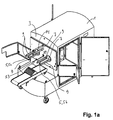
- Figures 1a and 1b is a schematic representation of the Device for producing kebab skewers with a housing 1 shown, in which in addition to the drive device for the rotary axes etc. also a separating device for the separation of prepared skewers and a spit unit for performing the spit process are accommodated, not discussed in more detail below becomes.
- two mutually parallel axes of rotation 5 are provided, namely a first axis of rotation 5a and a second axis of rotation 5b.
- a first axis of rotation 5a and a second axis of rotation 5b.
- three drive and safety rods 9 parallel to each Axis of rotation 5 are provided aligned.
- These each two drive and security rods 9 serve the purpose individual turntables, which will be explained below, function correctly to put on the axes 5, for which the based turntables explained in the following figures in addition to an axis of rotation bore 11 offset accordingly have lying drive and safety openings 13.
- the discs shown with reference to Figures 2 ff can therefore only be placed in one orientation be, the drive and safety rods 9 to the two turntables 7 for the two axes of rotation 5 in different Layers and, accordingly, the bores 13 can be introduced differently in the turntables, whereby the one provided turntables only on one axis of rotation 5a and that for the other axis of rotation 5b intended turntables only plugged in there correctly can be.
- a support rod 14 can be ready for use 1b still a roof-shaped finger protection device 16 are put on.
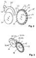
- FIG. 2 Based on Figure 2 is a perspective view a first filling or placement disk 15 is shown, some of which are also shown below as a pick and place 15b is referred to as it can be plugged on for the Rotation axis 5b on the right in FIG. 1 is suitable.
- This placement disk 15 or 15b has on the outer circumference staggered assembly chambers 17.
- the assembly chambers 17 are open on the radial side, the in Boundary walls extending outward towards the formation of an arcuate section 19 widen the radial insertion opening.
- the respective assembly chamber is 17 in axial alignment on one side open.
- the assembly chamber is on the opposite side 17 through a chamber wall 21 at least partially closed, leaving one radial gap 23, which also in the radial direction Formation of arcuate sections 25 is expanding.
- each an axial passage opening 29 is formed which will be discussed later.
- An assembly chamber 17 formed in this way is thus, for example pushed onto the right axis of rotation 5b, see above that the axis of rotation and the corresponding drive and Safety rods 9 the corresponding rotary axis bore 11 project through the drive / safety opening 13.
- part-circular Intermediate bar 35 is placed, the concave inner edge the cylindrical peripheral surface of the spacer 31 corresponds.
- This part-circular intermediate bar 35 each has a hook or a nose 37 with which them in a parallel to the axis of rotation from the machine side Front 3 firmly protruding anchoring rod 39 is plugged on.
- the part-circular intermediate strips do not rotate.
- a skewer skewer can be constructed in this way by putting the contents of e.g. eleven filling chambers, making six, for example Pieces of meat and in the five in between Five peppers / onion combinations put together can be.
- the axial thickness of the placement disks 15, for example for filling with meat or also for filling with peppers / onions can vary be large, with only those on the opposite side Axis arranged spacer a appropriate thickness must have.
- the thickness of the respective chamber walls provided with the radial slot 23 21 also ensures that the cavities of the assembly chambers 17 the one on the first as the second Rotation axis 5a, 5b mounted placement disks each to the thickness of these chamber walls 21 separately from each other come lying, so that ultimately the pieces of meat on corresponding to the skewer while maintaining an axial distance the thickness of the chamber wall 21 adjacent to the Pepper / onion combinations come to rest.
- the entire arrangement is such that the filled Axial congruent chambers in the central area congruent come to lie one behind the other, so that alternately those formed on the one placement disk 15 and assembly chambers 17 filled with meat and the Assembly chambers 17 of those provided on the second axis of rotation Placement disks 15 axially one behind the other lie.
- there is a feed opening in the front 3 of the housing 1 of the device automatically controlled a spit 51 out and through the meat / bell pepper / onion pieces parallel to the Rotary axes 5 inserted through.
- the mentioned axial passage openings 29 in the gear-like partition wall sections 27 are provided.
Landscapes
- Life Sciences & Earth Sciences (AREA)
- Engineering & Computer Science (AREA)
- Wood Science & Technology (AREA)
- Zoology (AREA)
- Food Science & Technology (AREA)
- Meat, Egg Or Seafood Products (AREA)
- Confectionery (AREA)
- Bakery Products And Manufacturing Methods Therefor (AREA)
- Baking, Grill, Roasting (AREA)
Description
- Figur 1a :
- eine schematische perspektivische Darstellung zum Herstellen von Lebensmittelspießen in geöffnetem Zustand bei abgenommenen Bestückungs- und Distanzscheiben;
- Figur 1b :
- eine zu Figur 1a entsprechende Darstellung in betriebsfertigen Zustand mit einer auf einer Auflagestange aufgesetzten, dach-förmigen Fingerschutz;
- Figur 2 :
- eine schematische perspektivische Darstellung zweier zusammenwirkender Befüllungsscheiben mit aufgesetzter Zwischenleiste vor dem Zusammenbau;
- Figur 3 :
- eine zu Figur 2 entsprechende Darstellung, wenn die Teile auf die Drehachsen aufgesetzt sind;
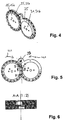
- Figur 4 :
- eine entsprechende Darstellung zu Figur 3, bei welcher eine weitere Bestückungs- und eine weitere Distanzscheibe aufgesetzt sind;
- Figur 5 :
- eine axiale Frontansicht auf das Ausführungsbeispiel nach Figur 4;
- Figur 6 :
- eine vergrößerte Schnittdarstellung längs der Linie A-A in Figur 5;
- Figur 7 :
- eine vergrößerte Detaildarstellung eines Ausschnitts aus Figur 3;
- Figur 8 :
- eine entsprechende Darstellung zu Figur 7, jedoch in einem anderen Blickwinkel;
- Figur 9 :
- eine vergrößerte Detaildarstellung bezüglich Figur 4 oder 5; und
- Figur 10 :
- eine perspektivische Darstellung der Vorrichtung zur Herstellung von Schaschlikspießen mit allen aufgesetzten Bestückungs- und Distanzscheiben sowie teilringförmigen Leisten.
Claims (17)
- Vorrichtung zur Herstellung von Schaschlikspießen und dergleichen gekennzeichnet durch die folgenden Merkmale:es sind zwei parallel und seitlich beabstandet angeordnete Dreh- oder Umlenk- oder Zentrierachsen (5; 5a, 5b) vorgesehen,auf den beiden Dreh-, Umlenk- oder Zentrierachsen (5; 5a, 5b) sinda) Bestückungsscheiben (15) drehbar angeordnet oder ausgebildet, und/oderb) es sind umlaufende Bestückungsbänder vorgesehen, die um Scheiben laufen oder drehen, die auf den beiden Dreh-, Umlenk- oder Zentrierachsen (5; 5a, 5b) angeordnet sind,die Bestückungsscheiben oder -bänder (15) weisen in Radialrichtung hin offene und in Umfangsrichtung versetzt liegende Bestückungskammern (17) zum Befüllen von Lebensmitteln, insbesondere von Fleischstückchen und/oder Gemüse-stückchen auf,die Bestückungsscheiben oder -bänder(15) sind auf den beiden Dreh-, Umlenk- oder Zentrierachsen (5a, 5b) so angeordnet, dass die Bestückungskammern (17) der auf der einen Dreh-, Umlenk- oder Zentrierachse (5a) angeordneten Bestückungsscheiben oder -bänder (15) axial versetzt liegen zu den Bestückungskammern (17), die in der auf der anderen Dreh-, Umlenk- oder Zentrierachse (5b) befindlichen Bestückungsscheiben oder -bänder (15) vorgesehen sind, unddie auf den Bestückungsscheiben oder -bändern (15) umlaufenden Bestückungskammern (17) kommen zumindest in einer Rotations- und/oder Fortbewegungsstellung jeweils in Axialrichtung hintereinander so zu liegen, dass in dieser Situation ein Spieß (51) axial durch die hintereinander liegenden Bestückungskammern (17) hindurchführbar und dadurch die in den Bestückungskammern (17) befindlichen Lebensmittelteile auf dem Spieß (51) aufspießbar sind.
- Vorrichtung nach Anspruch 1, dadurch gekennzeichnet, dass jeweils in axialer Höhe einer Bestückungsscheibe oder eines Bestückungsbandes (15) auf der dazu jeweils anderen Dreh-, Umlenk- oder Zentrierachse (5a, 5b) eine Distanzscheibe und/oder -einrichtung (31) vorgesehen ist, deren Außenumfang zumindest in einem Teilumfangsbereich ganz oder fast bis an den Außenumfang der mit den Bestückungskammern (17) versehenen Bestückungsscheibe (15) reicht.
- Vorrichtung nach Anspruch 2, dadurch gekennzeichnet, dass die Distanzscheibe oder -einrichtung (31) eine separate rotierende Scheibe ist.
- Vorrichtung nach Anspruch 2, dadurch gekennzeichnet, dass die Distanzscheibe (31) als axial vorstehender Scheibenansatz an einer Bestückungsscheibe (15) ausgebildet bzw. mit dieser fest verbunden ist.
- Vorrichtung nach einem der Ansprüche 1 bis 4, dadurch gekennzeichnet, dass der Überlappungsbereich der Bestückungsscheiben (15) bei axialer Ansicht parallel zu den Dreh-, Umlenk- oder Zentrierachsen (5; 5a, 5b, 5c) in etwa der radialen Höhe der Bestückungskammern (17) entspricht.
- Vorrichtung nach einem der Ansprüche 1 bis 5, dadurch gekennzeichnet, dass die Bestückungskammern (17) in Axialrichtung zumindest an einer Seite der Bestückungsscheibe (15) oder des Bestückungsbandes eine Kammerwand (21) aufweisen, wobei diese Kammerwand zumindest von einem mittleren Bereich der Bestückungskammern (17) ausgehend einen mit Radialkomponente, vorzugsweise mit sich nach außen hin in Umfangsrichtung erweiternder Radialkomponente verlaufenden Schlitz aufweist.
- Vorrichtung nach einem der Ansprüche 1 bis 6, dadurch gekennzeichnet, dass zumindest eine in Axialrichtung liegende Seite der Bestückungskammern (17) offen ist.
- Vorrichtung nach einem der Ansprüche 1 bis 7, dadurch gekennzeichnet, dass ferner eine teilkreisförmige Zwischenleiste (35) vorgesehen ist, die jeweils nicht rotierend auf der Distanzscheibe (31) aufgesetzt ist.
- Vorrichtung nach Anspruch 8, dadurch gekennzeichnet, dass die teilkreisförmige Zwischenleiste (35) eine axiale Dicke aufweist, die der axialen Dicke der damit zusammenwirkenden und auf der jeweils anderen Dreh-, Umlenk- oder Zentrierachse (5; 5a, 5b) sitzenden Bestückungsscheibe (15) bzw. des umlaufenden Bestückungsbandes entspricht.
- Vorrichtung nach Anspruch 8 oder 9, dadurch gekennzeichnet, dass die teilkreisförmige Zwischenleiste (35) eine teilkreisförmige Außenumfangsfläche aufweist, die in Höhe der mit den radialen Bestückungsöffnungen versehenen Umfangsfläche der benachbart sitzenden Bestückungsscheibe (15) endet.
- Vorrichtung nach einem der Ansprüche 1 bis 10, dadurch gekennzeichnet, dass während der Rotations- bzw. Fortbewegung der Bestückungsscheiben und/oder -bändern (15) die radial liegende Bestückungsöffnung auf eine Auflauffläche (45) aufläuft bzw. damit zusammenwirkt, wodurch gegebenenfalls über die radiale Bestückungsöffnung hinausstehende Lebensmittelteile in die Bestückungskammern (17) hineingedrückt werden.
- Vorrichtung nach Anspruch 10 oder 11, dadurch gekennzeichnet, dass die Auflauffläche (45) an der teilkreisförmigen Zwischenleiste (35) ausgebildet ist.
- Vorrichtung nach einem der Ansprüche 1 bis 12, dadurch gekennzeichnet, dass die zwischen den Bestückungskammern (17) verbleibenden zahnradähnlichen Zwischenwandabschnitte (27) an den Bestückungsscheiben (15) mit einer axialen Durchtrittsbohrung (29) versehen sind, die in der Aufspießposition axial miteinander fluchten.
- Vorrichtung nach Anspruch 13, dadurch gekennzeichnet, dass während des Aufspießvorganges ein Spieß (51) in Axialrichtung durch alle axial hintereinander liegenden Bestückungskammern (17) aller Bestückungsscheiben (15) maschinell hindurchgeführt wird, wobei der Spieß die in der jeweils einen Kammerwand (21) der Bestückungskammern (17) eingebrachten radialen Schlitze (23) druchragt.
- Vorrichtung nach einem der Ansprüche 1 bis 14, dadurch gekennzeichnet, dass während des Aufspießvorganges der durch die Bestückungskammern (17) hindurch gesteckte Spieß (51) durch einen parallel zu ihm verlaufenden Führungsstab (47) kontrolliert bewegt wird, wobei der Führungsstab (47) durch die in der Aufspießposition axial hintereinander fluchtenden Durchtrittsöffnungen (39) in den zahnradähnlichen Zwischenwandabschnitten bewegt wird.
- Vorrichtung nach Anspruch 15, dadurch gekennzeichnet, dass zunächst der Führungsstab (47) durch die fluchtenden Durchtrittsöffnungen (39) in den Zwischenwandabschnitten bewegbar ist, und erst nachfolgend, zumindest seitlich versetzt, der Spieß durch die Bestückungskammern (17) hindurch bewegbar ist.
- Vorrichtung nach einem der Ansprüche 1 bis 16, dadurch gekennzeichnet, dass die Dicke der Kammerwände (21) dem freien Axialabstand der auf dem Spieß aufgespießten Lebensmittel entspricht.
Applications Claiming Priority (3)
| Application Number | Priority Date | Filing Date | Title |
|---|---|---|---|
| DE10124119A DE10124119C2 (de) | 2001-05-17 | 2001-05-17 | Vorrichtung zur Herstellung von Schaschlikspießen |
| DE10124119 | 2001-05-17 | ||
| PCT/EP2002/005421 WO2002091839A1 (de) | 2001-05-17 | 2002-05-16 | Vorrichtung zur herstellung von lebensmittelspiessen, insbesondere von schaschlikspiessen und dergleichen |
Publications (2)
| Publication Number | Publication Date |
|---|---|
| EP1389045A1 EP1389045A1 (de) | 2004-02-18 |
| EP1389045B1 true EP1389045B1 (de) | 2004-09-08 |
Family
ID=7685192
Family Applications (1)
| Application Number | Title | Priority Date | Filing Date |
|---|---|---|---|
| EP02750939A Expired - Lifetime EP1389045B1 (de) | 2001-05-17 | 2002-05-16 | Vorrichtung zur herstellung von lebensmittelspiessen, insbesondere von schaschlikspiessen und dergleichen |
Country Status (4)
| Country | Link |
|---|---|
| EP (1) | EP1389045B1 (de) |
| AT (1) | ATE275346T1 (de) |
| DE (2) | DE10124119C2 (de) |
| WO (1) | WO2002091839A1 (de) |
Families Citing this family (6)
| Publication number | Priority date | Publication date | Assignee | Title |
|---|---|---|---|---|
| US7934448B2 (en) | 1999-10-26 | 2011-05-03 | Automated Food Systems, Inc. | Kebab machine |
| EP1464226B1 (de) | 2003-04-04 | 2006-06-21 | Maja-Maschinenfabrik Hermann Schill GmbH & Co. KG | Vorrichtung und Verfahren zum Herstellen von mit Lebensmitteln bestückten Spiessen |
| BE1016684A5 (fr) * | 2005-07-15 | 2007-04-03 | Service Distrib Viangros S A | Procede et dispositif pour la deformation de brochettes de viande. |
| US8025008B2 (en) | 2008-01-14 | 2011-09-27 | Automated Food Systems, Inc. | Kebab machine carrier |
| DE102008024201B3 (de) * | 2008-05-19 | 2010-01-28 | Völkl, Thomas | Grillfackelmaschine |
| DE202008008871U1 (de) * | 2008-10-13 | 2009-12-03 | Bendix, Conrad | Vorrichtung zur Herstellung eines Fleischspießes |
Family Cites Families (5)
| Publication number | Priority date | Publication date | Assignee | Title |
|---|---|---|---|---|
| US3835761A (en) * | 1973-06-18 | 1974-09-17 | T Yamanaka | Skewering machine |
| DE2625739A1 (de) * | 1976-06-09 | 1977-12-22 | Nordischer Maschinenbau | Maschine zum herstellen von fleischspiessen |
| FR2725591B1 (fr) * | 1994-10-17 | 1997-01-24 | Emsens Michel | Machine pour la fabrication automatique de brochettes de viandes et/ou de legumes |
| FR2760944B1 (fr) * | 1997-03-18 | 1999-04-23 | Michel Emsens | Machine pour la fabrication automatique de brochettes de viande ou de legumes enfilees sur des piques en bois notamment |
| FR2760945B1 (fr) * | 1997-03-20 | 1999-05-28 | Nijal | Procede de fabrication de brochettes et machines pour sa mise en oeuvre |
-
2001
- 2001-05-17 DE DE10124119A patent/DE10124119C2/de not_active Expired - Fee Related
-
2002
- 2002-05-16 EP EP02750939A patent/EP1389045B1/de not_active Expired - Lifetime
- 2002-05-16 WO PCT/EP2002/005421 patent/WO2002091839A1/de not_active Ceased
- 2002-05-16 AT AT02750939T patent/ATE275346T1/de not_active IP Right Cessation
- 2002-05-16 DE DE50200975T patent/DE50200975D1/de not_active Expired - Lifetime
Also Published As
| Publication number | Publication date |
|---|---|
| DE10124119C2 (de) | 2003-06-05 |
| EP1389045A1 (de) | 2004-02-18 |
| ATE275346T1 (de) | 2004-09-15 |
| WO2002091839A1 (de) | 2002-11-21 |
| DE10124119A1 (de) | 2002-11-28 |
| DE50200975D1 (de) | 2004-10-14 |
Similar Documents
| Publication | Publication Date | Title |
|---|---|---|
| DE3432958C2 (de) | ||
| DE2653490A1 (de) | Bemessungsscheibe | |
| DE602004001588T2 (de) | Vorrichtung und Verfahren zum Herstellen von Schaschlikspiessen | |
| EP2384267B1 (de) | Rotierendes schneidmesser für lebensmittel | |
| DE10124119C2 (de) | Vorrichtung zur Herstellung von Schaschlikspießen | |
| EP2017008A1 (de) | Schneidsatz mit zumindest einer Durchgangskanäle aufweisenden Loch- oder Trennscheibe | |
| DE69721001T2 (de) | Ausgabeplatte für einen nahrungsmittelautomaten | |
| DE2307575A1 (de) | Spiessgrillvorrichtung | |
| DE19545699C1 (de) | Grill mit einem motorisch drehbaren Fleischspieß | |
| DE3331745C2 (de) | ||
| DE4333096C2 (de) | Vorrichtung zum Raspeln oder Reiben von Nahrungsmitteln | |
| DE10057835A1 (de) | Vorrichtung zum Schneiden von Lebensmitteln | |
| EP3756840A1 (de) | Schneidsystem zum schneiden von obst oder gemüse in spiralförmige girlanden | |
| DE29715564U1 (de) | Aufsatz für ein Grillgerät | |
| DE3241107A1 (de) | Vorrichtung fuer die anordnung von grill- oder bratgut sowie verfahren zur durchfuehrung der anordnung | |
| DE2448403A1 (de) | Vorrichtung zur waermebehandlung von nahrungsmitteln | |
| EP1055492B1 (de) | Maschine zum Schneiden von Lebensmitteln, insbesondere von Gemüse, in Streifen | |
| EP3898137B1 (de) | Presseinheit für portioniermaschine | |
| DE10136610B4 (de) | Reversible Klemmvorrichtung für einen Grill | |
| DE370405C (de) | Verfahren und Vorrichtung zur Herstellung von Rollmops | |
| DE3033673A1 (de) | Geraet zum zerschneiden von nahrungsmitteln wie fruechte und gemuese | |
| DE19832945C2 (de) | Vorrichtung zum Schneiden von Lebensmitteln | |
| DE19816264A1 (de) | Gerät zum Poltern und ggfs. auch zum Stegen von Fleisch | |
| DE2317747A1 (de) | Vorrichtung zur behandlung von zu panierenden fleisch- bzw. fischstuecken in filetform od. dgl | |
| DE19524439C1 (de) | Mürbschneider mit Gewürzdosierung |
Legal Events
| Date | Code | Title | Description |
|---|---|---|---|
| PUAI | Public reference made under article 153(3) epc to a published international application that has entered the european phase |
Free format text: ORIGINAL CODE: 0009012 |
|
| GRAP | Despatch of communication of intention to grant a patent |
Free format text: ORIGINAL CODE: EPIDOSNIGR1 |
|
| 17P | Request for examination filed |
Effective date: 20031030 |
|
| AK | Designated contracting states |
Kind code of ref document: A1 Designated state(s): AT BE CH CY DE DK ES FI FR GB GR IE IT LI LU MC NL PT SE TR |
|
| AX | Request for extension of the european patent |
Extension state: AL LT LV MK RO SI |
|
| GRAS | Grant fee paid |
Free format text: ORIGINAL CODE: EPIDOSNIGR3 |
|
| GRAA | (expected) grant |
Free format text: ORIGINAL CODE: 0009210 |
|
| AK | Designated contracting states |
Kind code of ref document: B1 Designated state(s): AT BE CH CY DE DK ES FI FR GB GR IE IT LI LU MC NL PT SE TR |
|
| PG25 | Lapsed in a contracting state [announced via postgrant information from national office to epo] |
Ref country code: FR Free format text: LAPSE BECAUSE OF FAILURE TO SUBMIT A TRANSLATION OF THE DESCRIPTION OR TO PAY THE FEE WITHIN THE PRESCRIBED TIME-LIMIT Effective date: 20040908 Ref country code: IT Free format text: LAPSE BECAUSE OF FAILURE TO SUBMIT A TRANSLATION OF THE DESCRIPTION OR TO PAY THE FEE WITHIN THE PRESCRIBED TIME-LIMIT;WARNING: LAPSES OF ITALIAN PATENTS WITH EFFECTIVE DATE BEFORE 2007 MAY HAVE OCCURRED AT ANY TIME BEFORE 2007. THE CORRECT EFFECTIVE DATE MAY BE DIFFERENT FROM THE ONE RECORDED. Effective date: 20040908 Ref country code: GB Free format text: LAPSE BECAUSE OF FAILURE TO SUBMIT A TRANSLATION OF THE DESCRIPTION OR TO PAY THE FEE WITHIN THE PRESCRIBED TIME-LIMIT Effective date: 20040908 Ref country code: IE Free format text: LAPSE BECAUSE OF FAILURE TO SUBMIT A TRANSLATION OF THE DESCRIPTION OR TO PAY THE FEE WITHIN THE PRESCRIBED TIME-LIMIT Effective date: 20040908 Ref country code: TR Free format text: LAPSE BECAUSE OF FAILURE TO SUBMIT A TRANSLATION OF THE DESCRIPTION OR TO PAY THE FEE WITHIN THE PRESCRIBED TIME-LIMIT Effective date: 20040908 Ref country code: NL Free format text: LAPSE BECAUSE OF FAILURE TO SUBMIT A TRANSLATION OF THE DESCRIPTION OR TO PAY THE FEE WITHIN THE PRESCRIBED TIME-LIMIT Effective date: 20040908 Ref country code: FI Free format text: LAPSE BECAUSE OF FAILURE TO SUBMIT A TRANSLATION OF THE DESCRIPTION OR TO PAY THE FEE WITHIN THE PRESCRIBED TIME-LIMIT Effective date: 20040908 |
|
| REG | Reference to a national code |
Ref country code: GB Ref legal event code: FG4D Free format text: NOT ENGLISH |
|
| REG | Reference to a national code |
Ref country code: CH Ref legal event code: EP |
|
| REG | Reference to a national code |
Ref country code: IE Ref legal event code: FG4D Free format text: GERMAN |
|
| REF | Corresponds to: |
Ref document number: 50200975 Country of ref document: DE Date of ref document: 20041014 Kind code of ref document: P |
|
| PG25 | Lapsed in a contracting state [announced via postgrant information from national office to epo] |
Ref country code: SE Free format text: LAPSE BECAUSE OF FAILURE TO SUBMIT A TRANSLATION OF THE DESCRIPTION OR TO PAY THE FEE WITHIN THE PRESCRIBED TIME-LIMIT Effective date: 20041208 Ref country code: GR Free format text: LAPSE BECAUSE OF FAILURE TO SUBMIT A TRANSLATION OF THE DESCRIPTION OR TO PAY THE FEE WITHIN THE PRESCRIBED TIME-LIMIT Effective date: 20041208 Ref country code: DK Free format text: LAPSE BECAUSE OF FAILURE TO SUBMIT A TRANSLATION OF THE DESCRIPTION OR TO PAY THE FEE WITHIN THE PRESCRIBED TIME-LIMIT Effective date: 20041208 |
|
| PG25 | Lapsed in a contracting state [announced via postgrant information from national office to epo] |
Ref country code: ES Free format text: LAPSE BECAUSE OF FAILURE TO SUBMIT A TRANSLATION OF THE DESCRIPTION OR TO PAY THE FEE WITHIN THE PRESCRIBED TIME-LIMIT Effective date: 20041219 |
|
| LTIE | Lt: invalidation of european patent or patent extension |
Effective date: 20040908 |
|
| NLV1 | Nl: lapsed or annulled due to failure to fulfill the requirements of art. 29p and 29m of the patents act | ||
| GBV | Gb: ep patent (uk) treated as always having been void in accordance with gb section 77(7)/1977 [no translation filed] |
Effective date: 20040908 |
|
| REG | Reference to a national code |
Ref country code: IE Ref legal event code: FD4D |
|
| PG25 | Lapsed in a contracting state [announced via postgrant information from national office to epo] |
Ref country code: LU Free format text: LAPSE BECAUSE OF NON-PAYMENT OF DUE FEES Effective date: 20050516 Ref country code: CY Free format text: LAPSE BECAUSE OF FAILURE TO SUBMIT A TRANSLATION OF THE DESCRIPTION OR TO PAY THE FEE WITHIN THE PRESCRIBED TIME-LIMIT Effective date: 20050516 Ref country code: AT Free format text: LAPSE BECAUSE OF NON-PAYMENT OF DUE FEES Effective date: 20050516 |
|
| PG25 | Lapsed in a contracting state [announced via postgrant information from national office to epo] |
Ref country code: BE Free format text: LAPSE BECAUSE OF NON-PAYMENT OF DUE FEES Effective date: 20050531 Ref country code: MC Free format text: LAPSE BECAUSE OF NON-PAYMENT OF DUE FEES Effective date: 20050531 |
|
| PLBE | No opposition filed within time limit |
Free format text: ORIGINAL CODE: 0009261 |
|
| STAA | Information on the status of an ep patent application or granted ep patent |
Free format text: STATUS: NO OPPOSITION FILED WITHIN TIME LIMIT |
|
| 26N | No opposition filed |
Effective date: 20050609 |
|
| EN | Fr: translation not filed | ||
| BERE | Be: lapsed |
Owner name: *VOLKL THOMAS Effective date: 20050531 |
|
| PG25 | Lapsed in a contracting state [announced via postgrant information from national office to epo] |
Ref country code: LI Free format text: LAPSE BECAUSE OF NON-PAYMENT OF DUE FEES Effective date: 20060531 Ref country code: CH Free format text: LAPSE BECAUSE OF NON-PAYMENT OF DUE FEES Effective date: 20060531 |
|
| REG | Reference to a national code |
Ref country code: CH Ref legal event code: PL |
|
| BERE | Be: lapsed |
Owner name: *VOLKL THOMAS Effective date: 20050531 |
|
| PG25 | Lapsed in a contracting state [announced via postgrant information from national office to epo] |
Ref country code: PT Free format text: LAPSE BECAUSE OF NON-PAYMENT OF DUE FEES Effective date: 20050208 |
|
| PGFP | Annual fee paid to national office [announced via postgrant information from national office to epo] |
Ref country code: DE Payment date: 20100526 Year of fee payment: 9 |
|
| REG | Reference to a national code |
Ref country code: DE Ref legal event code: R119 Ref document number: 50200975 Country of ref document: DE Effective date: 20111201 |
|
| PG25 | Lapsed in a contracting state [announced via postgrant information from national office to epo] |
Ref country code: DE Free format text: LAPSE BECAUSE OF NON-PAYMENT OF DUE FEES Effective date: 20111201 |