EP1388593B1 - Schnelles Verfahren zur Herstellung von Mehrfachlagen-Barriereschichten - Google Patents
Schnelles Verfahren zur Herstellung von Mehrfachlagen-Barriereschichten Download PDFInfo
- Publication number
- EP1388593B1 EP1388593B1 EP03017033.6A EP03017033A EP1388593B1 EP 1388593 B1 EP1388593 B1 EP 1388593B1 EP 03017033 A EP03017033 A EP 03017033A EP 1388593 B1 EP1388593 B1 EP 1388593B1
- Authority
- EP
- European Patent Office
- Prior art keywords
- layer
- range
- organic
- inorganic
- coating
- Prior art date
- Legal status (The legal status is an assumption and is not a legal conclusion. Google has not performed a legal analysis and makes no representation as to the accuracy of the status listed.)
- Expired - Lifetime
Links
- 238000000034 method Methods 0.000 title claims description 134
- 230000004888 barrier function Effects 0.000 title claims description 96
- 238000000576 coating method Methods 0.000 title claims description 89
- 230000008569 process Effects 0.000 title claims description 74
- 239000010410 layer Substances 0.000 claims description 197
- 239000011248 coating agent Substances 0.000 claims description 78
- 239000000758 substrate Substances 0.000 claims description 46
- 239000002131 composite material Substances 0.000 claims description 31
- 238000000151 deposition Methods 0.000 claims description 30
- 230000000694 effects Effects 0.000 claims description 27
- 239000007789 gas Substances 0.000 claims description 25
- 230000008021 deposition Effects 0.000 claims description 24
- 239000002243 precursor Substances 0.000 claims description 24
- QVGXLLKOCUKJST-UHFFFAOYSA-N atomic oxygen Chemical compound [O] QVGXLLKOCUKJST-UHFFFAOYSA-N 0.000 claims description 23
- 229910052760 oxygen Inorganic materials 0.000 claims description 23
- 239000001301 oxygen Substances 0.000 claims description 23
- 239000012044 organic layer Substances 0.000 claims description 18
- 239000004033 plastic Substances 0.000 claims description 15
- 229920003023 plastic Polymers 0.000 claims description 15
- 230000006872 improvement Effects 0.000 claims description 13
- 239000000463 material Substances 0.000 claims description 12
- 238000009792 diffusion process Methods 0.000 claims description 9
- 230000007704 transition Effects 0.000 claims description 7
- UQEAIHBTYFGYIE-UHFFFAOYSA-N hexamethyldisiloxane Chemical compound C[Si](C)(C)O[Si](C)(C)C UQEAIHBTYFGYIE-UHFFFAOYSA-N 0.000 claims description 6
- 239000000203 mixture Substances 0.000 claims description 6
- 230000008859 change Effects 0.000 claims description 4
- 239000003989 dielectric material Substances 0.000 claims description 3
- 229910010272 inorganic material Inorganic materials 0.000 claims description 3
- 239000011147 inorganic material Substances 0.000 claims description 3
- 239000011368 organic material Substances 0.000 claims description 3
- 229910052710 silicon Inorganic materials 0.000 claims description 2
- 239000010703 silicon Substances 0.000 claims description 2
- XUIMIQQOPSSXEZ-UHFFFAOYSA-N Silicon Chemical compound [Si] XUIMIQQOPSSXEZ-UHFFFAOYSA-N 0.000 claims 1
- 238000000259 microwave plasma-assisted chemical vapour deposition Methods 0.000 claims 1
- 150000002894 organic compounds Chemical class 0.000 claims 1
- 238000002203 pretreatment Methods 0.000 claims 1
- 230000000717 retained effect Effects 0.000 claims 1
- 229920002994 synthetic fiber Polymers 0.000 claims 1
- 210000002381 plasma Anatomy 0.000 description 25
- FFUAGWLWBBFQJT-UHFFFAOYSA-N hexamethyldisilazane Chemical compound C[Si](C)(C)N[Si](C)(C)C FFUAGWLWBBFQJT-UHFFFAOYSA-N 0.000 description 16
- 238000012360 testing method Methods 0.000 description 14
- 239000002318 adhesion promoter Substances 0.000 description 12
- 230000004907 flux Effects 0.000 description 11
- 238000000623 plasma-assisted chemical vapour deposition Methods 0.000 description 11
- 230000008901 benefit Effects 0.000 description 9
- 229920000139 polyethylene terephthalate Polymers 0.000 description 7
- 239000005020 polyethylene terephthalate Substances 0.000 description 7
- 239000007788 liquid Substances 0.000 description 6
- 238000004806 packaging method and process Methods 0.000 description 5
- 239000000047 product Substances 0.000 description 5
- 239000004743 Polypropylene Substances 0.000 description 4
- FFBHFFJDDLITSX-UHFFFAOYSA-N benzyl N-[2-hydroxy-4-(3-oxomorpholin-4-yl)phenyl]carbamate Chemical compound OC1=C(NC(=O)OCC2=CC=CC=C2)C=CC(=C1)N1CCOCC1=O FFBHFFJDDLITSX-UHFFFAOYSA-N 0.000 description 4
- 238000004519 manufacturing process Methods 0.000 description 4
- 229920001155 polypropylene Polymers 0.000 description 4
- 239000000126 substance Substances 0.000 description 4
- VYPSYNLAJGMNEJ-UHFFFAOYSA-N Silicium dioxide Chemical compound O=[Si]=O VYPSYNLAJGMNEJ-UHFFFAOYSA-N 0.000 description 3
- 229910003481 amorphous carbon Inorganic materials 0.000 description 3
- 238000005229 chemical vapour deposition Methods 0.000 description 3
- 238000013467 fragmentation Methods 0.000 description 3
- 238000006062 fragmentation reaction Methods 0.000 description 3
- 230000035699 permeability Effects 0.000 description 3
- -1 polypropylene Polymers 0.000 description 3
- 239000011241 protective layer Substances 0.000 description 3
- XLYOFNOQVPJJNP-UHFFFAOYSA-N water Chemical compound O XLYOFNOQVPJJNP-UHFFFAOYSA-N 0.000 description 3
- OKTJSMMVPCPJKN-UHFFFAOYSA-N Carbon Chemical compound [C] OKTJSMMVPCPJKN-UHFFFAOYSA-N 0.000 description 2
- 229910052799 carbon Inorganic materials 0.000 description 2
- 238000006243 chemical reaction Methods 0.000 description 2
- 150000001875 compounds Chemical class 0.000 description 2
- 238000009826 distribution Methods 0.000 description 2
- 229920000307 polymer substrate Polymers 0.000 description 2
- 238000004886 process control Methods 0.000 description 2
- 239000007858 starting material Substances 0.000 description 2
- 238000009827 uniform distribution Methods 0.000 description 2
- 230000003213 activating effect Effects 0.000 description 1
- 230000004913 activation Effects 0.000 description 1
- 230000001464 adherent effect Effects 0.000 description 1
- 239000000853 adhesive Substances 0.000 description 1
- 230000001070 adhesive effect Effects 0.000 description 1
- 239000012790 adhesive layer Substances 0.000 description 1
- 239000012298 atmosphere Substances 0.000 description 1
- 238000000071 blow moulding Methods 0.000 description 1
- 239000007767 bonding agent Substances 0.000 description 1
- 238000012512 characterization method Methods 0.000 description 1
- 239000007795 chemical reaction product Substances 0.000 description 1
- 239000000470 constituent Substances 0.000 description 1
- 239000002537 cosmetic Substances 0.000 description 1
- 238000005336 cracking Methods 0.000 description 1
- 230000007547 defect Effects 0.000 description 1
- 230000032798 delamination Effects 0.000 description 1
- 238000013461 design Methods 0.000 description 1
- 238000001514 detection method Methods 0.000 description 1
- 238000011161 development Methods 0.000 description 1
- 230000018109 developmental process Effects 0.000 description 1
- 238000004090 dissolution Methods 0.000 description 1
- 238000013401 experimental design Methods 0.000 description 1
- 238000002474 experimental method Methods 0.000 description 1
- 238000005429 filling process Methods 0.000 description 1
- 239000012634 fragment Substances 0.000 description 1
- 238000009499 grossing Methods 0.000 description 1
- 230000005764 inhibitory process Effects 0.000 description 1
- 238000009434 installation Methods 0.000 description 1
- 230000010354 integration Effects 0.000 description 1
- 150000002500 ions Chemical class 0.000 description 1
- 230000009191 jumping Effects 0.000 description 1
- 238000005259 measurement Methods 0.000 description 1
- 230000000877 morphologic effect Effects 0.000 description 1
- 238000006053 organic reaction Methods 0.000 description 1
- 239000005022 packaging material Substances 0.000 description 1
- 238000005375 photometry Methods 0.000 description 1
- 238000004375 physisorption Methods 0.000 description 1
- 229920000642 polymer Polymers 0.000 description 1
- 238000001556 precipitation Methods 0.000 description 1
- 238000005086 pumping Methods 0.000 description 1
- 230000005855 radiation Effects 0.000 description 1
- 238000004064 recycling Methods 0.000 description 1
- 230000009467 reduction Effects 0.000 description 1
- 238000012216 screening Methods 0.000 description 1
- 238000004904 shortening Methods 0.000 description 1
- 235000012239 silicon dioxide Nutrition 0.000 description 1
- 239000000377 silicon dioxide Substances 0.000 description 1
- 229910052814 silicon oxide Inorganic materials 0.000 description 1
- 230000002195 synergetic effect Effects 0.000 description 1
- 238000010998 test method Methods 0.000 description 1
- 238000002834 transmittance Methods 0.000 description 1
- 230000000007 visual effect Effects 0.000 description 1
Images
Classifications
-
- C—CHEMISTRY; METALLURGY
- C23—COATING METALLIC MATERIAL; COATING MATERIAL WITH METALLIC MATERIAL; CHEMICAL SURFACE TREATMENT; DIFFUSION TREATMENT OF METALLIC MATERIAL; COATING BY VACUUM EVAPORATION, BY SPUTTERING, BY ION IMPLANTATION OR BY CHEMICAL VAPOUR DEPOSITION, IN GENERAL; INHIBITING CORROSION OF METALLIC MATERIAL OR INCRUSTATION IN GENERAL
- C23C—COATING METALLIC MATERIAL; COATING MATERIAL WITH METALLIC MATERIAL; SURFACE TREATMENT OF METALLIC MATERIAL BY DIFFUSION INTO THE SURFACE, BY CHEMICAL CONVERSION OR SUBSTITUTION; COATING BY VACUUM EVAPORATION, BY SPUTTERING, BY ION IMPLANTATION OR BY CHEMICAL VAPOUR DEPOSITION, IN GENERAL
- C23C16/00—Chemical coating by decomposition of gaseous compounds, without leaving reaction products of surface material in the coating, i.e. chemical vapour deposition [CVD] processes
- C23C16/22—Chemical coating by decomposition of gaseous compounds, without leaving reaction products of surface material in the coating, i.e. chemical vapour deposition [CVD] processes characterised by the deposition of inorganic material, other than metallic material
- C23C16/30—Deposition of compounds, mixtures or solid solutions, e.g. borides, carbides, nitrides
-
- B—PERFORMING OPERATIONS; TRANSPORTING
- B05—SPRAYING OR ATOMISING IN GENERAL; APPLYING FLUENT MATERIALS TO SURFACES, IN GENERAL
- B05D—PROCESSES FOR APPLYING FLUENT MATERIALS TO SURFACES, IN GENERAL
- B05D1/00—Processes for applying liquids or other fluent materials
- B05D1/62—Plasma-deposition of organic layers
-
- C—CHEMISTRY; METALLURGY
- C23—COATING METALLIC MATERIAL; COATING MATERIAL WITH METALLIC MATERIAL; CHEMICAL SURFACE TREATMENT; DIFFUSION TREATMENT OF METALLIC MATERIAL; COATING BY VACUUM EVAPORATION, BY SPUTTERING, BY ION IMPLANTATION OR BY CHEMICAL VAPOUR DEPOSITION, IN GENERAL; INHIBITING CORROSION OF METALLIC MATERIAL OR INCRUSTATION IN GENERAL
- C23C—COATING METALLIC MATERIAL; COATING MATERIAL WITH METALLIC MATERIAL; SURFACE TREATMENT OF METALLIC MATERIAL BY DIFFUSION INTO THE SURFACE, BY CHEMICAL CONVERSION OR SUBSTITUTION; COATING BY VACUUM EVAPORATION, BY SPUTTERING, BY ION IMPLANTATION OR BY CHEMICAL VAPOUR DEPOSITION, IN GENERAL
- C23C16/00—Chemical coating by decomposition of gaseous compounds, without leaving reaction products of surface material in the coating, i.e. chemical vapour deposition [CVD] processes
- C23C16/02—Pretreatment of the material to be coated
- C23C16/0272—Deposition of sub-layers, e.g. to promote the adhesion of the main coating
- C23C16/029—Graded interfaces
-
- C—CHEMISTRY; METALLURGY
- C23—COATING METALLIC MATERIAL; COATING MATERIAL WITH METALLIC MATERIAL; CHEMICAL SURFACE TREATMENT; DIFFUSION TREATMENT OF METALLIC MATERIAL; COATING BY VACUUM EVAPORATION, BY SPUTTERING, BY ION IMPLANTATION OR BY CHEMICAL VAPOUR DEPOSITION, IN GENERAL; INHIBITING CORROSION OF METALLIC MATERIAL OR INCRUSTATION IN GENERAL
- C23C—COATING METALLIC MATERIAL; COATING MATERIAL WITH METALLIC MATERIAL; SURFACE TREATMENT OF METALLIC MATERIAL BY DIFFUSION INTO THE SURFACE, BY CHEMICAL CONVERSION OR SUBSTITUTION; COATING BY VACUUM EVAPORATION, BY SPUTTERING, BY ION IMPLANTATION OR BY CHEMICAL VAPOUR DEPOSITION, IN GENERAL
- C23C16/00—Chemical coating by decomposition of gaseous compounds, without leaving reaction products of surface material in the coating, i.e. chemical vapour deposition [CVD] processes
- C23C16/04—Coating on selected surface areas, e.g. using masks
- C23C16/045—Coating cavities or hollow spaces, e.g. interior of tubes; Infiltration of porous substrates
-
- C—CHEMISTRY; METALLURGY
- C23—COATING METALLIC MATERIAL; COATING MATERIAL WITH METALLIC MATERIAL; CHEMICAL SURFACE TREATMENT; DIFFUSION TREATMENT OF METALLIC MATERIAL; COATING BY VACUUM EVAPORATION, BY SPUTTERING, BY ION IMPLANTATION OR BY CHEMICAL VAPOUR DEPOSITION, IN GENERAL; INHIBITING CORROSION OF METALLIC MATERIAL OR INCRUSTATION IN GENERAL
- C23C—COATING METALLIC MATERIAL; COATING MATERIAL WITH METALLIC MATERIAL; SURFACE TREATMENT OF METALLIC MATERIAL BY DIFFUSION INTO THE SURFACE, BY CHEMICAL CONVERSION OR SUBSTITUTION; COATING BY VACUUM EVAPORATION, BY SPUTTERING, BY ION IMPLANTATION OR BY CHEMICAL VAPOUR DEPOSITION, IN GENERAL
- C23C16/00—Chemical coating by decomposition of gaseous compounds, without leaving reaction products of surface material in the coating, i.e. chemical vapour deposition [CVD] processes
- C23C16/22—Chemical coating by decomposition of gaseous compounds, without leaving reaction products of surface material in the coating, i.e. chemical vapour deposition [CVD] processes characterised by the deposition of inorganic material, other than metallic material
- C23C16/30—Deposition of compounds, mixtures or solid solutions, e.g. borides, carbides, nitrides
- C23C16/40—Oxides
- C23C16/401—Oxides containing silicon
- C23C16/402—Silicon dioxide
-
- C—CHEMISTRY; METALLURGY
- C23—COATING METALLIC MATERIAL; COATING MATERIAL WITH METALLIC MATERIAL; CHEMICAL SURFACE TREATMENT; DIFFUSION TREATMENT OF METALLIC MATERIAL; COATING BY VACUUM EVAPORATION, BY SPUTTERING, BY ION IMPLANTATION OR BY CHEMICAL VAPOUR DEPOSITION, IN GENERAL; INHIBITING CORROSION OF METALLIC MATERIAL OR INCRUSTATION IN GENERAL
- C23C—COATING METALLIC MATERIAL; COATING MATERIAL WITH METALLIC MATERIAL; SURFACE TREATMENT OF METALLIC MATERIAL BY DIFFUSION INTO THE SURFACE, BY CHEMICAL CONVERSION OR SUBSTITUTION; COATING BY VACUUM EVAPORATION, BY SPUTTERING, BY ION IMPLANTATION OR BY CHEMICAL VAPOUR DEPOSITION, IN GENERAL
- C23C16/00—Chemical coating by decomposition of gaseous compounds, without leaving reaction products of surface material in the coating, i.e. chemical vapour deposition [CVD] processes
- C23C16/44—Chemical coating by decomposition of gaseous compounds, without leaving reaction products of surface material in the coating, i.e. chemical vapour deposition [CVD] processes characterised by the method of coating
- C23C16/50—Chemical coating by decomposition of gaseous compounds, without leaving reaction products of surface material in the coating, i.e. chemical vapour deposition [CVD] processes characterised by the method of coating using electric discharges
- C23C16/515—Chemical coating by decomposition of gaseous compounds, without leaving reaction products of surface material in the coating, i.e. chemical vapour deposition [CVD] processes characterised by the method of coating using electric discharges using pulsed discharges
-
- C—CHEMISTRY; METALLURGY
- C23—COATING METALLIC MATERIAL; COATING MATERIAL WITH METALLIC MATERIAL; CHEMICAL SURFACE TREATMENT; DIFFUSION TREATMENT OF METALLIC MATERIAL; COATING BY VACUUM EVAPORATION, BY SPUTTERING, BY ION IMPLANTATION OR BY CHEMICAL VAPOUR DEPOSITION, IN GENERAL; INHIBITING CORROSION OF METALLIC MATERIAL OR INCRUSTATION IN GENERAL
- C23C—COATING METALLIC MATERIAL; COATING MATERIAL WITH METALLIC MATERIAL; SURFACE TREATMENT OF METALLIC MATERIAL BY DIFFUSION INTO THE SURFACE, BY CHEMICAL CONVERSION OR SUBSTITUTION; COATING BY VACUUM EVAPORATION, BY SPUTTERING, BY ION IMPLANTATION OR BY CHEMICAL VAPOUR DEPOSITION, IN GENERAL
- C23C28/00—Coating for obtaining at least two superposed coatings either by methods not provided for in a single one of groups C23C2/00 - C23C26/00 or by combinations of methods provided for in subclasses C23C and C25C or C25D
-
- B—PERFORMING OPERATIONS; TRANSPORTING
- B05—SPRAYING OR ATOMISING IN GENERAL; APPLYING FLUENT MATERIALS TO SURFACES, IN GENERAL
- B05D—PROCESSES FOR APPLYING FLUENT MATERIALS TO SURFACES, IN GENERAL
- B05D7/00—Processes, other than flocking, specially adapted for applying liquids or other fluent materials to particular surfaces or for applying particular liquids or other fluent materials
- B05D7/50—Multilayers
- B05D7/56—Three layers or more
-
- B—PERFORMING OPERATIONS; TRANSPORTING
- B29—WORKING OF PLASTICS; WORKING OF SUBSTANCES IN A PLASTIC STATE IN GENERAL
- B29C—SHAPING OR JOINING OF PLASTICS; SHAPING OF MATERIAL IN A PLASTIC STATE, NOT OTHERWISE PROVIDED FOR; AFTER-TREATMENT OF THE SHAPED PRODUCTS, e.g. REPAIRING
- B29C49/00—Blow-moulding, i.e. blowing a preform or parison to a desired shape within a mould; Apparatus therefor
- B29C49/42—Component parts, details or accessories; Auxiliary operations
- B29C49/64—Heating or cooling preforms, parisons or blown articles
- B29C49/6604—Thermal conditioning of the blown article
- B29C49/6605—Heating the article, e.g. for hot fill
Definitions
- the invention relates to a rapid process for applying alternating layers by means of chemical vapor deposition, chemical vapor deposition, CVD, plasma enhanced chemical vapor deposition (PECVD), plasma enhanced chemical vapor deposition (PICVD), plasma impulse chemical vapor deposition, and coatings, which can be applied by this method.
- An improvement of the coating process is carried out in a conventional manner on the basis of the process parameters power, pressure and time.
- HMDSO separates organic and TiCl 4 inorganic barrier layers.
- this application does not describe how fast process times can be achieved and how the fast process can be realized for containers with a larger volume> 18 ml, typically> 50 ml.
- the sample throughput also depends on the number of stations required on a coating machine, so that the number of stations required can be reduced by very short coating times or, conversely, with the same number of stations, the sample throughput can be increased, resulting in significant cost advantages.
- WO 99/49991 describes a barrier coating with amorphous carbon, in which a fast process with coating times in the range of 2 to 3 s is achieved.
- these layers are not transparent, but rather have a brownish to yellow color.
- this coloration is very unaesthetic and often leads to unacceptable results. If these layers are applied thinly, although the color is lower, it is still present.
- the barrier effect is significantly deteriorated.
- these layers of amorphous carbon are very difficult and expensive to remove from the PET substrate. For this reason, the recycling of the coated containers is problematic because even when blended with uncoated PET, a color cast may still remain in the recycled product.
- Coating times of 2 to 4 s for an SiO x barrier layer are also disclosed in the patents WO 02/09891 A1 and WO 02/10473 described. However, these publications do not specify by which process parameters the stated coating times can be set. Specifically, there is a lack of precise information on pressure, concentration, microwave power and precursor as well as the carrier and reactive gas flows.
- a method for coating plastic bottles wherein first a barrier layer of silicon dioxide and then an organic layer is applied to the substrate.
- the layers which are applied from different starting compounds, consist of a protective layer of amorphous carbon, an SiOx layer and a boundary layer to the substrate, made of oxygen and an "organo-silicon-containing" compound. This process is very complicated, since a total of 3 layers are applied and very different starting compounds must be used. Also in the claims 1-10 of WO 02/09891 A1 a similar complex procedure is described.
- alternating layers are produced solely from a precursor material.
- a fast and easy to implement process control is possible, which also allows in particular the specified in claim 1 fast process times.
- a transition between organic and inorganic layers can be made variable, and it can also very smooth layers apply, whereby by the interfaces between organic and inorganic layers enhancement of the barrier effect is achieved.
- the invention provides for the total flux for the second inorganic layer to be equal to or greater than the total flux for the first organic adhesion promoter layer.
- the deposition rate for the second layer can thus be significantly increased for the latter case, so that the total coating time can be further reduced.
- the quality of the barrier layer can be maintained at a low precursor concentration and, at the same time, the deposition rate can be increased significantly, so that a significantly reduced coating time is made possible for the second inorganic barrier layer with the same layer thickness.
- the solution according to the invention thus makes available for the first time a method for applying alternating layers, that is to say of at least 2 layers, by means of PECVD, in particular PICVD, processes comprising the rapid precipitation of a primer layer on a substrate and the application of a barrier layer alternately alternating layers of organic and inorganic materials are deposited. Preferably, only 2 layers are deposited. This enables particularly fast process times to be realized.
- PECVD in particular PICVD
- the alternating layers can advantageously be deposited from only a single Precursorgas Precursorgasen, namely hexamethyldisiloxane or hexamethyldisilazane for both layers or hexamethyldisiloxane for the first organic and hexamethyldisilazane for the second inorganic layer.
- the method is characterized in that the coating time for applying the adhesion promoter layer is between 0.05 s and 4 s, and / or the coating time for applying the barrier layer is between 0.1 s and 6 s.
- coating time is meant the period in which a layer is deposited on the substrate and during which a continuous or a pulsed plasma burns.
- barrier layers particularly on dielectric materials
- a high density of topological or chemical inhomogeneities can lead to increased permeability of the layer.
- the diffusion through the interfaces between organic and inorganic layers is significantly inhibited in alternating layers or the diffusion path is significantly extended.
- the alternating layers according to the invention are deposited by varying at least one process parameter.
- the inventors have found that the use of a plasma-assisted CVD process, a so-called PICVD process, can deposit particularly well-adhering layers with an outstanding barrier effect in a very short process time.
- a plasma-assisted CVD process a so-called PICVD process
- very thin layers can be applied to a substrate material, which nevertheless is very good Have barrier properties.
- the layers also have a high flexibility.
- PICVD PICVD
- a plasma generated by means of microwaves is used during the deposition of the layers.
- Microwaves of a frequency of 2.45 GHz are preferably used.
- the plasma generated by means of microwaves is pulsed.
- the lance length by means of which the precursor gas was introduced into the container to be coated, can be advantageously adapted in order to be able to realize a uniform distribution of the components in the process gas in the container.
- the lance length is defined as the distance between the opening, flows from the gas into the container to be coated and the outer edge of the container opening of the container to be coated, which is sealed against the atmosphere.
- the invention also provides for adjusting the pulse pause to an increased overall flow. At higher total flow, the pulse break is shortened.
- the pulse pause determines the length of time that fresh process gas can flow into the container before a plasma is ignited and coating takes place.
- the pressure the total flow, the precursor concentration, the lance length and the nozzle diameter, a good distribution of the components of the process gas can already be achieved with shorter pulse pauses and thus the process sequence can be accelerated once again.
- the deposition rate in pulsed plasmas does not necessarily have to be lower than in so-called “continuous wave plasmas (CW plasmas)", because with suitably determined parameters in the pulsed plasma within the pulse duration an almost complete substance conversion can take place and within the pulse pause new fresh gas flows in, which is almost completely implemented at the next pulse again.
- CW plasmas continuous wave plasmas
- the rate of deposition in pulsed plasmas may even be higher if the fresh process gas flows in timely and then during the pulse with high pulse power, a higher mass conversion takes place than in a CW plasma with lower instantaneous power. With a shorter pulse pause, the deposition rate increases significantly to an optimum, since the proportion of reacted precursor gas increases to saturation.
- the deposition rate for the organic layer is in the range of 120 nm / min to 5000 nm / min, preferably in the range of 500 nm / min to 2000 nm / min, and / or for the inorganic layer in the range of 60 nm / min to 2000 nm / min, preferably in the range of 100 nm / min to 1000 nm / min.
- the uniformity is defined as the ratio of the minimum layer thickness to the maximum layer thickness, the values being determined by measurement over said substrate.
- the lance length is in the range of 5% to 80%, preferably in the range of 10% to 50% of the height of a hollow body to be coated.
- pulsed plasma Another advantage of the pulsed plasma is that very pure inorganic barrier layers can be produced because unlike the CW plasma unwanted organic reaction products can be removed in the pulse interval and thus a much lower proportion of organic constituents incorporated in the layers.
- the at least one process parameter to be varied is selected from the group comprising the precursor concentration, the average microwave power, the pressure, the pulse power, the pulse duration, the duration of the pulse pause and the total flow. These parameters offer the possibility to deposit high-quality barrier layers with a very short coating time. All mentioned process parameters relate to the coating of a single substrate. For the coating of many substrates in a multi-station system, for example a rotary or batch system with a plurality of chambers, the parameters mentioned each refer to the coating in a single chamber.
- the parameters are set to optimum values for this purpose.
- the pulse power for the organic layer in the range of 100 W to 5000 W, preferably in the range of 400 W and 1500 W, and / or that the pulse power for the second inorganic layer in the range of 100 W to 5000 W, preferably in the range of 400 W to 1500 W.
- the average microwave power is according to the invention for the organic layer in the range of 10 W and 5000 W, preferably in the range of 10 W and 500 W, and / or for the inorganic layer in the range of 10 W to 5000 W, preferably in the range of 30 W. and 2000 W.
- the barrier coating may also particularly advantageously have a composition or structure that varies perpendicularly to the coated surface of the substrate.
- the variation can be continuous or stepwise.
- a stepwise variation results in a multilayer barrier coating.
- the lowermost layer which is in contact with the surface of the substrate, can serve as a primer layer for the subsequent coatings.
- Such layers or layer systems can be produced, for example, by continuous or stepwise change of the precursor concentration during the coating.
- the substrate material to be coated may also comprise in particular a hollow body.
- a coating can thus be deposited on the inside and / or outside of the hollow body.
- the invention further advantageously provides, as substrate, a hollow body, preferably simultaneously, to evacuate on the outside to a pressure p 1 and to pump off the inside to a base pressure p 2 ⁇ p 1 , the pressure p 1 in particular in the range around 50 mbar and the base pressure p 2 is in particular below 0.1 mbar.
- the method according to the invention to pass a precursor-containing gas mixture at a pressure p 3 with p 2 ⁇ p 3 ⁇ p 1 into the interior of the substrate, the pressure p 3 in particular for the first organic layer in the range of 0.1 mbar to 1.0 mbar, preferably in the range of 0.2 mbar to 0.5 mbar, and for the second inorganic layer in the range of 0.1 mbar to 1.0 mbar, preferably in the range of 0.25 mbar to 0.6 mbar lies.
- This is advantageously achieved that act on the walls of the hollow body not too large pressure differences, which could lead to deformation of the hollow body with thin-walled material.
- the exclusive inner coating may choose the external pressure so that no plasma is ignited in the outer space.
- the method is advantageous in the total flow and / or the pressure p 3 in the interior of the substrate during deposition of the inorganic barrier layer is at least equal, in particular higher than the total flow and / or the pressure p 3 in the interior of the substrate during deposition of the organic adhesive layer. Therefore, with the invention, a significantly higher deposition rate when applying the inorganic barrier layer can be achieved than at a lower total flux.
- the process gas for a layer is inventively admitted at a pressure p 4 , which is higher than the pressure p 5 immediately before the ignition of the plasma.
- a pressure p 4 which is higher than the pressure p 5 immediately before the ignition of the plasma.
- the total flux for the organic adhesion promoter layer is in the range from 10 sccm to 250 sccm, preferably in the range from 40 sccm to 100 sccm, and for the inorganic layer in the range from 200 sccm to 1000 sccm, preferably in the range from 250 sccm to 400 sccm ,
- the method is also characterized in that when changing the process parameters in the transition between two coating steps, the plasma either continues to burn or is interrupted for a transitional period.
- the invention allows a soft continuous transition in the form of a gradient or a hard transition in the form of a stage and also given the opportunity to save energy.
- the transition time for a pulsed plasma is greater than the pulse pause.
- the process according to the invention fundamentally makes a pretreatment of the substrate superfluous.
- a plasma pretreatment may also be carried out with the method prior to the application of the coating.
- the duration of the plasma pretreatment is below 5 s, preferably below 1 s.
- the solution according to the invention comprises various possibilities for varying the process parameters.
- the at least one process parameter can be varied continuously or discontinuously; alternatively, the at least one process parameter can be varied partially continuously and / or partially discontinuously.
- an organic layer is advantageously first deposited on the substrate as an adhesion promoter layer.
- an adhesion promoter layer is advantageously first deposited on the substrate as an adhesion promoter layer.
- the precursor When the adhesion promoter layer is deposited, the precursor is fragmented.
- the fragmentation of the precursor is influenced in such a way that individual fragments in the form of atoms, molecules, ions or radicals react with the molecules of the substrate to be coated and enter into a chemical bond (chemisorption). This binding is preferred over physisorption. Due to the strong bond as a result of the fragmentation of the precursor, the layer adhesion is improved. Due to fragmentation arises in particular an organic adhesion promoter layer with a carbon content of more than 10%.
- the process parameters further influence the growth of the adhesion promoter layer in such a way that the organic layer is advantageously deposited in the layer growth on the substrate and has only a few defects in the form of internal boundary surfaces.
- the primer layer is thus very smooth and may itself have a barrier effect because it has very few interfaces that could serve as paths for rapid diffusion.
- the adhesion promoter layer Under suitable conditions, it is also possible to achieve a smoothing effect on a rough plastic substrate by the adhesion promoter layer.
- An advantage of the smooth adhesion promoter layer is that it can be applied to an inorganic layer with good barrier effect, while adhesion promoter layers with rough morphology, only an inorganic can be applied with a significantly reduced barrier effect.
- the inorganic barrier layer used is sufficient for non-polar plastics, such as polypropylene, for a good layer adhesion. It is a procedural advantage that the method according to the invention can be dispensed with a time-consuming plasma pretreatment for activating the surface, as could be done, for example, by an oxygen plasma according to the documents cited above.
- an inorganic layer is deposited as a barrier layer.
- the barrier effect is enhanced by this barrier layer due to the interfaces between the organic and the dense, also smooth, inorganic layers.
- jumping in morphology for example from layer growth to column growth or island growth, the diffusion paths along the interfaces are significantly lengthened.
- the interfaces changed bonding conditions in relation to the interior of the layers before, whereby the permeation in these areas is difficult.
- the inventive method can be carried out using different precursors, in particular it is provided that the gas mixture contains oxygen and a precursor HMDSN or HMDSO.
- the method according to the invention makes it possible to apply barrier coatings having particularly long diffusion paths, the method advantageously being used for packaging, In particular, plastic packaging can be applied.
- the invention comprises, in addition to the method, a composite material consisting of alternating layers which alternately consists of organic and inorganic materials which have been deposited from a single precursor gas.
- the composite material also advantageously has an increased barrier effect, increased adhesion to the substrate, increased extensibility, increased mechanical stability under pressure and / or increased mechanical stability under pressure. After stretching and / or plastic deformation with changes in length of more than 4%, a barrier improvement with an oxygen barrier improvement factor greater than 1.5, preferably greater than 2.0, remains with the composite material according to the invention.
- An advantage of the composite material is also that it has a high mechanical stability, especially under strain load by carbonated, under overpressure liquids. Containers of the composite material according to the invention are therefore particularly suitable for such liquids.
- the coating according to the invention generally offers advantages when used in particular on substrates which comprise or form containers for foamed products or products with dissolved gases.
- the coating has at least one organic adhesion promoter layer whose thickness is in the range of 1 nm to 200 nm, and at least one inorganic barrier layer having a thickness of 5 nm to 200 nm.
- the invention makes it possible for the first time to produce such good layer qualities in rapid process times below 6 s, that even with the layer thicknesses in the stated range, the requirements for barrier effect, adhesion, ductility and mechanical stability under pressure can be met.
- the coating of the invention allows the application of a very fast coating process with surprisingly high quality of the barrier.
- the composite material is also temperature resistant.
- the temperature resistance is defined by the fact that after hot filling the layers adhere and a barrier effect is present.
- the invention thus offers the advantage that there is essentially no detachment of the barrier coating as a result of the temperature load, and that even after the temperature load there is still a good barrier effect.
- the coating according to the invention also has good resistance to filling with hot liquids, as for example for HOT-FILL bottles or containers for other products used for hot filling. Even with these containers, the process can be implemented with a very short coating time.
- the composite material may comprise a cover layer.
- a protective layer can be provided.
- cover layer may include lettering or other designs of the coated substrate.
- the composite material of the invention is substantially transparent, unlike conventional carbon-based processes.
- transparent is meant a layer that is transparent in the visible wavelength range, which means that the visual transmittance (illuminant D65) is not less than that for an uncoated bottle.
- This container can be produced with the invention, in which on the one hand the product can be recognized from the outside unadulterated and on the other hand allow it to visually monitor the content. This may be important in medical or biotechnology applications such as photometric measurements.
- a bottle of polyethylene terephthalate (PET) with a filling volume of 0.4 l is simultaneously evacuated on the outside to a pressure of 50 mbar and the inside initially pumped to a base pressure below 0.1 mbar.
- PET polyethylene terephthalate
- HMDSN hexamethyldisilazane
- pulsed microwave energy is coupled in at a frequency of 2.45 GHz and a plasma is ignited in the container.
- a first 10 nm thick organic barrier layer applied at a HMDSN concentration of 40% and a total flux of 40 sccm.
- the pulse power is 800 W, the pulse duration preferably 0.7 ms and the pulse pause is 40 ms.
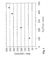
- the parameters layer thickness or coating time and the other process parameters oxygen fluxes and pulse conduction, pulse duration and pulse pause and the plant parameter lance length are varied in screening experiments with constant HMDSN concentration and constant pressure.
- Fig. 1 a comparison between the set oxygen flow and the measured deposition rate is shown.
- the deposition rate of the second inorganic layer can be significantly increased.
- Table 1 shows a selection of investigated process parameters for the second inorganic layer, in which the composite of first and second layer gives a high barrier effect.
- the coating time and deposition rate of the second inorganic layer carried out directly after the coating and after a stress test (Creep test with 4 vol .-% CO 2 ).
- a stress test with 4 vol .-% CO 2 .
- TABLE 1 Coating time and deposition rate of the second inorganic layer as a function of process and installation parameters as well as inhibition of barking (BIF) of the 2-layer composite from 1st organic and 2 nd inorganic layer, directly after the coating and after a stress test (4% creep) Test with 4 vol .-% CO ⁇ sub> 2 ⁇ / sub>).
- the barrier improvement factor, BIF is defined as the ratio of the permeation of an uncoated substrate relative to the permeation of a coated substrate.
- the data indicate that process 1, where the oxygen flux is 100 sccm, the pulse pause is 50 ms, and the lance length is 102 mm, a deposition rate of 86 nm / min is achieved.
- the coating time is relatively long at 14 seconds.
- the deposition rates of processes 2, 3 and 4 at 200, 318 and 360 nm / min, respectively are clear due to the higher oxygen fluxes of 220, 380 and 450 sccm and due to the shortened pulse interval to 40 ms, as well as the improved lance length of 50 mm higher.
- the coating time can be significantly reduced.
- the thickness of the second layer has been reduced. Overall, this reduces the resulting coating time to values of 2 to 6 seconds.
- the coating can be used to produce a bonding agent barrier composite with a high oxygen barrier improvement factor (O 2 -BIF), which has a value of significantly> 40 for processes 1, 2 and 3.
- O 2 -BIF oxygen barrier improvement factor
- the permeation of an uncoated bottle is 0.1955 cm 3 / (pack day ⁇ bar).
- the permeation of the coated bottle is so low that the dissolution limit of the Mocon-Oxtran measuring device used has been reached.
- an O 2 -BIF of 30 is determined.
- the coated bottles are filled for the creep test with 0.4 l of carbonated liquid with a CO 2 content of 4% and sealed with a plastic cap. Subsequently, the filled bottles are first stored at room temperature for 24 hours and then at 38 ° C. for 24 hours.
- the bond is so stable that a clearly detectable barrier effect is maintained despite this high load.
- This effect is due to the fact that despite the high elongation and / or plastic deformation no delamination due to the good adhesion occurs, and for a large part of the surface of the coated substrate no cracking in the composite results, by which the barrier effect is deteriorated.
- the fastest process has a slightly reduced but still very high post-coating barrier improvement, and as good a barrier improvement after the creep test as the slower process 1.
- the processes of the first embodiment are repeated several times.
- a HOT-FILL bottle of crystalline PET with a volume of 0.5 1 is coated with the same process parameters as in Process 2 of Example 1.
- a hot-fillable bottle is referred to as usual, which shows essentially no change in size when filled with a liquid having a temperature between 85 ° C. and 95 ° C.
- the coating time is 1.3 s for the first organic layer and 5.3 s for the second inorganic layer.
- An uncoated HOT-FILL bottle has an oxygen permeation of 0.192 cm 3 / (pack ⁇ day ⁇ bar), a. coated bottles have an oxygen permeation below the detection limit of 0.04 cm 3 / (pack day bar) and thus an O 2 -BIF of more than 40.
- coated bottles are first incubated at 35 ° C and 95% relative humidity for one hour Humidity stored. The bottles are then filled to 0.5 l with 95 ° C hot water, the temperature is initially maintained for 5 minutes lying and then the filled container is cooled in a cold water bath for 20 minutes to room temperature.
- a bottle of polypropylene (PP) with a filling volume of 0.6 1 is coated with the same process parameters as in Process 2 of Example 1. Due to the changed bottle shape, the deposition rate changes.
- the coating time is 1 s for the first organic layer and 5.6 s for the second inorganic layer.
- a primer barrier composite with high O 2 barrier improvement factor O 2 -BIF.
- the layers are very adhesive and stretch-resistant. In the present case, there is no need for plasma pretreatment or activation of the substrate, as could be done, for example, with an oxygen plasma.
Landscapes
- Chemical & Material Sciences (AREA)
- Engineering & Computer Science (AREA)
- Organic Chemistry (AREA)
- Chemical Kinetics & Catalysis (AREA)
- Materials Engineering (AREA)
- Mechanical Engineering (AREA)
- Metallurgy (AREA)
- General Chemical & Material Sciences (AREA)
- Inorganic Chemistry (AREA)
- Physics & Mathematics (AREA)
- Plasma & Fusion (AREA)
- Chemical Vapour Deposition (AREA)
- Details Of Rigid Or Semi-Rigid Containers (AREA)
- Laminated Bodies (AREA)
- Application Of Or Painting With Fluid Materials (AREA)
- Physical Vapour Deposition (AREA)
Priority Applications (1)
| Application Number | Priority Date | Filing Date | Title |
|---|---|---|---|
| EP03017033.6A EP1388593B1 (de) | 2002-08-07 | 2003-07-28 | Schnelles Verfahren zur Herstellung von Mehrfachlagen-Barriereschichten |
Applications Claiming Priority (5)
| Application Number | Priority Date | Filing Date | Title |
|---|---|---|---|
| WOPCT/EP02/08853 | 2002-08-07 | ||
| PCT/EP2002/008853 WO2003014415A1 (de) | 2001-08-07 | 2002-08-07 | Verbundmaterial aus einem substratmaterial und einem barriereschichtmaterial |
| DE10258678 | 2002-12-13 | ||
| DE10258678A DE10258678B4 (de) | 2002-12-13 | 2002-12-13 | Schnelles Verfahren zur Herstellung von Multilayer-Barriereschichten |
| EP03017033.6A EP1388593B1 (de) | 2002-08-07 | 2003-07-28 | Schnelles Verfahren zur Herstellung von Mehrfachlagen-Barriereschichten |
Publications (3)
| Publication Number | Publication Date |
|---|---|
| EP1388593A2 EP1388593A2 (de) | 2004-02-11 |
| EP1388593A3 EP1388593A3 (de) | 2004-08-25 |
| EP1388593B1 true EP1388593B1 (de) | 2015-12-30 |
Family
ID=32031495
Family Applications (1)
| Application Number | Title | Priority Date | Filing Date |
|---|---|---|---|
| EP03017033.6A Expired - Lifetime EP1388593B1 (de) | 2002-08-07 | 2003-07-28 | Schnelles Verfahren zur Herstellung von Mehrfachlagen-Barriereschichten |
Country Status (3)
| Country | Link |
|---|---|
| EP (1) | EP1388593B1 (enExample) |
| JP (1) | JP4426790B2 (enExample) |
| CN (1) | CN100381606C (enExample) |
Cited By (1)
| Publication number | Priority date | Publication date | Assignee | Title |
|---|---|---|---|---|
| US11684546B2 (en) | 2013-03-11 | 2023-06-27 | Sio2 Medical Products, Inc. | PECVD coated pharmaceutical packaging |
Families Citing this family (30)
| Publication number | Priority date | Publication date | Assignee | Title |
|---|---|---|---|---|
| DE102004017236B4 (de) * | 2004-04-05 | 2012-10-25 | Schott Ag | Verbundmaterial mit verbesserter chemischer Beständigkeit und Verfahren zu dessen Herstellung |
| DE102004028369B4 (de) * | 2004-06-11 | 2007-05-31 | Schott Ag | Verfahren und Vorrichtung zum Behandeln von Substraten in einer Rundläuferanlage |
| JP2006089073A (ja) * | 2004-09-22 | 2006-04-06 | Hokkai Can Co Ltd | 内面被覆プラスチック容器及びその製造方法 |
| DE102004061464B4 (de) * | 2004-12-17 | 2008-12-11 | Schott Ag | Substrat mit feinlaminarer Barriereschutzschicht und Verfahren zu dessen Herstellung |
| US7906217B2 (en) | 2005-02-22 | 2011-03-15 | Toyo Seikan Kaisha, Ltd. | Vapor deposited film by plasma CVD method |
| WO2007044181A2 (en) * | 2005-10-05 | 2007-04-19 | Dow Corning Corporation | Coated substrates and methods for their preparation |
| JP5159422B2 (ja) * | 2008-05-15 | 2013-03-06 | 北海製罐株式会社 | ポリエステル樹脂製容器 |
| DK2251454T3 (da) | 2009-05-13 | 2014-10-13 | Sio2 Medical Products Inc | Coating og inspektion af beholder |
| US9618413B2 (en) * | 2010-02-24 | 2017-04-11 | Belanos Clean Power Holding AG | Self-monitoring composite vessel for high pressure media |
| US11624115B2 (en) | 2010-05-12 | 2023-04-11 | Sio2 Medical Products, Inc. | Syringe with PECVD lubrication |
| DE102010048960A1 (de) * | 2010-10-18 | 2012-04-19 | Khs Corpoplast Gmbh | Verfahren und Vorrichtung zur Plasmabehandlung von Werkstücken |
| US9878101B2 (en) | 2010-11-12 | 2018-01-30 | Sio2 Medical Products, Inc. | Cyclic olefin polymer vessels and vessel coating methods |
| DE102010063887B4 (de) * | 2010-12-22 | 2012-07-19 | BSH Bosch und Siemens Hausgeräte GmbH | Verfahren zum Herstellen eines pyrolysetauglichen Bauteils eines Gargeräts sowie pyrolysetaugliches Bauteil für ein Gargerät |
| DE102011005234A1 (de) | 2011-03-08 | 2012-09-13 | Fraunhofer-Gesellschaft zur Förderung der angewandten Forschung e.V. | Gasbarriereschichtsystem |
| AU2012318242A1 (en) | 2011-11-11 | 2013-05-30 | Sio2 Medical Products, Inc. | Passivation, pH protective or lubricity coating for pharmaceutical package, coating process and apparatus |
| US11116695B2 (en) | 2011-11-11 | 2021-09-14 | Sio2 Medical Products, Inc. | Blood sample collection tube |
| US20140012115A1 (en) * | 2012-07-03 | 2014-01-09 | Medtronic Minimed, Inc. | Plasma deposited adhesion promoter layers for use with analyte sensors |
| US20150297800A1 (en) | 2012-07-03 | 2015-10-22 | Sio2 Medical Products, Inc. | SiOx BARRIER FOR PHARMACEUTICAL PACKAGE AND COATING PROCESS |
| CA2890066C (en) | 2012-11-01 | 2021-11-09 | Sio2 Medical Products, Inc. | Coating inspection method |
| WO2014078666A1 (en) | 2012-11-16 | 2014-05-22 | Sio2 Medical Products, Inc. | Method and apparatus for detecting rapid barrier coating integrity characteristics |
| EP2925903B1 (en) | 2012-11-30 | 2022-04-13 | Si02 Medical Products, Inc. | Controlling the uniformity of pecvd deposition on medical syringes, cartridges, and the like |
| US9764093B2 (en) | 2012-11-30 | 2017-09-19 | Sio2 Medical Products, Inc. | Controlling the uniformity of PECVD deposition |
| EP2961858B1 (en) | 2013-03-01 | 2022-09-07 | Si02 Medical Products, Inc. | Coated syringe. |
| US9937099B2 (en) | 2013-03-11 | 2018-04-10 | Sio2 Medical Products, Inc. | Trilayer coated pharmaceutical packaging with low oxygen transmission rate |
| EP2971227B1 (en) | 2013-03-15 | 2017-11-15 | Si02 Medical Products, Inc. | Coating method. |
| CN104752633A (zh) * | 2013-12-31 | 2015-07-01 | 中国科学院微电子研究所 | 一种薄膜封装方法 |
| EP3693493A1 (en) | 2014-03-28 | 2020-08-12 | SiO2 Medical Products, Inc. | Antistatic coatings for plastic vessels |
| US11077233B2 (en) | 2015-08-18 | 2021-08-03 | Sio2 Medical Products, Inc. | Pharmaceutical and other packaging with low oxygen transmission rate |
| CN110195218A (zh) * | 2019-05-20 | 2019-09-03 | 何金宁 | 一种微波cvd纳米防水复合工艺 |
| US20220306525A1 (en) * | 2021-03-25 | 2022-09-29 | Schott Ag | Coated glass element |
Family Cites Families (9)
| Publication number | Priority date | Publication date | Assignee | Title |
|---|---|---|---|---|
| US5009920A (en) * | 1990-03-30 | 1991-04-23 | Honeywell Inc. | Method for applying optical interference coating |
| DE4239234A1 (de) * | 1992-11-21 | 1994-06-09 | Krupp Widia Gmbh | Werkzeug und Verfahren zur Beschichtung eines Werkzeuggrundkörpers |
| FR2703073B1 (fr) * | 1993-03-26 | 1995-05-05 | Lorraine Laminage | Procédé et dispositif pour le revêtement en continu d'un matériau métallique en défilement par un dépôt de polymère à gradient de composition, et produit obtenu par ce procédé. |
| FR2730990B1 (fr) * | 1995-02-23 | 1997-04-04 | Saint Gobain Vitrage | Substrat transparent a revetement anti-reflets |
| JPH11513713A (ja) * | 1995-10-13 | 1999-11-24 | ザ ダウ ケミカル カンパニー | コートされたプラスチック基材 |
| DE19634795C2 (de) * | 1996-08-29 | 1999-11-04 | Schott Glas | Plasma-CVD-Anlage mit einem Array von Mikrowellen-Plasmaelektroden und Plasma-CVD-Verfahren |
| CN1298963A (zh) * | 1999-12-09 | 2001-06-13 | 中国科学技术大学 | 金属氧化物或合金薄膜的化学气相淀积方法及装置 |
| CN1432035A (zh) * | 2000-06-06 | 2003-07-23 | 陶氏化学公司 | 用于聚合物与容器的阻隔层 |
| FR2812666B1 (fr) * | 2000-08-01 | 2003-08-08 | Sidel Sa | Revetement barriere comportant une couche protectrice, procede d'obtention d'un tel revetement et recipient muni d'un tel revetement |
-
2003
- 2003-07-28 EP EP03017033.6A patent/EP1388593B1/de not_active Expired - Lifetime
- 2003-08-07 JP JP2003288821A patent/JP4426790B2/ja not_active Expired - Lifetime
- 2003-08-07 CN CNB031275567A patent/CN100381606C/zh not_active Expired - Lifetime
Cited By (1)
| Publication number | Priority date | Publication date | Assignee | Title |
|---|---|---|---|---|
| US11684546B2 (en) | 2013-03-11 | 2023-06-27 | Sio2 Medical Products, Inc. | PECVD coated pharmaceutical packaging |
Also Published As
| Publication number | Publication date |
|---|---|
| JP2004068159A (ja) | 2004-03-04 |
| CN1552943A (zh) | 2004-12-08 |
| EP1388593A3 (de) | 2004-08-25 |
| EP1388593A2 (de) | 2004-02-11 |
| CN100381606C (zh) | 2008-04-16 |
| JP4426790B2 (ja) | 2010-03-03 |
Similar Documents
| Publication | Publication Date | Title |
|---|---|---|
| EP1388593B1 (de) | Schnelles Verfahren zur Herstellung von Mehrfachlagen-Barriereschichten | |
| WO2012089196A1 (de) | Verfahren zur plasmabehandlung von werkstücken sowie werkstück mit gasbarriereschicht | |
| DE102006058771B4 (de) | Behälter mit verbesserter Restentleerbarkeit und Verfahren zu dessen Herstellung | |
| EP1388594B1 (de) | Verfahren zum Herstellen von glatten Barriereschichten und Verbundmaterial mit glatter Barriereschicht | |
| DE69902027T2 (de) | Behälter mit einer beschichtung mit sperreigenschaften und verfahren zu seiner herstellung | |
| EP0709485B1 (de) | Verfahren zur Herstellung eines Behälters aus Kunststoff mit einer Sperrbeschichtung | |
| EP2836439B1 (de) | Beschichtung von behältern mit plasmadüsen | |
| DE69705552T2 (de) | Verfahren zur Plasmaverarbeitung | |
| DE102004001603B4 (de) | Behälter mit Innendekor | |
| DE69815359T2 (de) | Plastikbehälter mit einer externen gassperrenbeschichtung | |
| DE4408250A1 (de) | Verfahren zum Beschichten der Oberfläche eines Substrats und Beschichtungsmaterial | |
| EP2911875B1 (de) | Verbundmaterial für ein pharmazeutisches packmittel, verfahren zu dessen herstellung und verwendung des verbundmaterials | |
| DE10258678B4 (de) | Schnelles Verfahren zur Herstellung von Multilayer-Barriereschichten | |
| EP2630273B1 (de) | Verfahren zur plasmabehandlung von werkstücken | |
| WO2005073427A2 (de) | Verfahren zur herstellung eines ultrabarriere-schichtsystems | |
| EP0930238B1 (de) | Befüllter und verschlossener Kunststoffbehälter und Verfahren zu seiner Herstellung | |
| DE10258681A1 (de) | Verfahren zum Herstellen von glatten Barriereschichten und Verbundmaterial mit glatter Barriereschicht | |
| EP2721192B1 (de) | Verfahren zur plasmabehandlung von werkstücken | |
| EP4045695B1 (de) | Vorrichtung und verfahren zum recyclen von getränkeflaschen aus kunststoff | |
| DE102004017241B4 (de) | Verbundmaterial und Verfahren zu seiner Herstellung | |
| DE60005405T2 (de) | Mit einer gas- und aroma-diffusionssperrschicht beschichtete flexible tube | |
| DE102023132995A1 (de) | Verfahren zum Beschichten von Mehrwegbehältern, nach diesem Verfahren hergestellte Behälter und Behälterbeschichtungsmaschine zum Beschichten von Mehrweg-Kunststoffbehältern | |
| EP2551374A1 (de) | Verfahren zur Erzeugung einer permeationshemmenden Beschichtung von Kunststoffbehältern und Beschichtungsanlage | |
| DE102018003838A1 (de) | Vorrichtung sowie Verfahren zur Beschichtung und beschichtete Behälter | |
| EP2166130A1 (de) | Kunststoffilm mit guter Barrierewirkung nach einer Sterilisierbehandlung |
Legal Events
| Date | Code | Title | Description |
|---|---|---|---|
| PUAI | Public reference made under article 153(3) epc to a published international application that has entered the european phase |
Free format text: ORIGINAL CODE: 0009012 |
|
| 17P | Request for examination filed |
Effective date: 20030809 |
|
| AK | Designated contracting states |
Kind code of ref document: A2 Designated state(s): AT BE BG CH CY CZ DE DK EE ES FI FR GB GR HU IE IT LI LU MC NL PT RO SE SI SK TR |
|
| AX | Request for extension of the european patent |
Extension state: AL LT LV MK |
|
| PUAL | Search report despatched |
Free format text: ORIGINAL CODE: 0009013 |
|
| AK | Designated contracting states |
Kind code of ref document: A3 Designated state(s): AT BE BG CH CY CZ DE DK EE ES FI FR GB GR HU IE IT LI LU MC NL PT RO SE SI SK TR |
|
| AX | Request for extension of the european patent |
Extension state: AL LT LV MK |
|
| RIC1 | Information provided on ipc code assigned before grant |
Ipc: 7C 23C 28/00 B Ipc: 7C 23C 16/40 B Ipc: 7C 23C 16/30 B Ipc: 7C 23C 16/515 A Ipc: 7B 65D 65/42 B |
|
| RAP1 | Party data changed (applicant data changed or rights of an application transferred) |
Owner name: SCHOTT AG |
|
| AKX | Designation fees paid |
Designated state(s): AT BE BG CH CY CZ DE DK EE ES FI FR GB GR HU IE IT LI LU MC NL PT RO SE SI SK TR |
|
| 17Q | First examination report despatched |
Effective date: 20061002 |
|
| 17Q | First examination report despatched |
Effective date: 20061002 |
|
| REG | Reference to a national code |
Ref country code: DE Ref legal event code: R079 Ref document number: 50315388 Country of ref document: DE Free format text: PREVIOUS MAIN CLASS: C23C0016515000 Ipc: B05D0001000000 |
|
| GRAP | Despatch of communication of intention to grant a patent |
Free format text: ORIGINAL CODE: EPIDOSNIGR1 |
|
| RIC1 | Information provided on ipc code assigned before grant |
Ipc: C23C 16/30 20060101ALI20150629BHEP Ipc: C23C 16/515 20060101ALI20150629BHEP Ipc: C23C 16/40 20060101ALI20150629BHEP Ipc: B05D 1/00 20060101AFI20150629BHEP Ipc: B05D 7/00 20060101ALI20150629BHEP Ipc: C23C 28/00 20060101ALI20150629BHEP Ipc: C23C 16/04 20060101ALI20150629BHEP Ipc: C23C 16/02 20060101ALI20150629BHEP |
|
| INTG | Intention to grant announced |
Effective date: 20150716 |
|
| GRAS | Grant fee paid |
Free format text: ORIGINAL CODE: EPIDOSNIGR3 |
|
| GRAA | (expected) grant |
Free format text: ORIGINAL CODE: 0009210 |
|
| AK | Designated contracting states |
Kind code of ref document: B1 Designated state(s): AT BE BG CH CY CZ DE DK EE ES FI FR GB GR HU IE IT LI LU MC NL PT RO SE SI SK TR |
|
| REG | Reference to a national code |
Ref country code: GB Ref legal event code: FG4D Free format text: NOT ENGLISH |
|
| REG | Reference to a national code |
Ref country code: CH Ref legal event code: EP |
|
| REG | Reference to a national code |
Ref country code: AT Ref legal event code: REF Ref document number: 767211 Country of ref document: AT Kind code of ref document: T Effective date: 20160115 |
|
| REG | Reference to a national code |
Ref country code: IE Ref legal event code: FG4D Free format text: LANGUAGE OF EP DOCUMENT: GERMAN |
|
| REG | Reference to a national code |
Ref country code: DE Ref legal event code: R096 Ref document number: 50315388 Country of ref document: DE |
|
| REG | Reference to a national code |
Ref country code: NL Ref legal event code: MP Effective date: 20151230 |
|
| PG25 | Lapsed in a contracting state [announced via postgrant information from national office to epo] |
Ref country code: SE Free format text: LAPSE BECAUSE OF FAILURE TO SUBMIT A TRANSLATION OF THE DESCRIPTION OR TO PAY THE FEE WITHIN THE PRESCRIBED TIME-LIMIT Effective date: 20151230 Ref country code: FI Free format text: LAPSE BECAUSE OF FAILURE TO SUBMIT A TRANSLATION OF THE DESCRIPTION OR TO PAY THE FEE WITHIN THE PRESCRIBED TIME-LIMIT Effective date: 20151230 Ref country code: GR Free format text: LAPSE BECAUSE OF FAILURE TO SUBMIT A TRANSLATION OF THE DESCRIPTION OR TO PAY THE FEE WITHIN THE PRESCRIBED TIME-LIMIT Effective date: 20160331 |
|
| PG25 | Lapsed in a contracting state [announced via postgrant information from national office to epo] |
Ref country code: NL Free format text: LAPSE BECAUSE OF FAILURE TO SUBMIT A TRANSLATION OF THE DESCRIPTION OR TO PAY THE FEE WITHIN THE PRESCRIBED TIME-LIMIT Effective date: 20151230 |
|
| REG | Reference to a national code |
Ref country code: FR Ref legal event code: PLFP Year of fee payment: 14 |
|
| PG25 | Lapsed in a contracting state [announced via postgrant information from national office to epo] |
Ref country code: CZ Free format text: LAPSE BECAUSE OF FAILURE TO SUBMIT A TRANSLATION OF THE DESCRIPTION OR TO PAY THE FEE WITHIN THE PRESCRIBED TIME-LIMIT Effective date: 20151230 Ref country code: ES Free format text: LAPSE BECAUSE OF FAILURE TO SUBMIT A TRANSLATION OF THE DESCRIPTION OR TO PAY THE FEE WITHIN THE PRESCRIBED TIME-LIMIT Effective date: 20151230 |
|
| PG25 | Lapsed in a contracting state [announced via postgrant information from national office to epo] |
Ref country code: PT Free format text: LAPSE BECAUSE OF FAILURE TO SUBMIT A TRANSLATION OF THE DESCRIPTION OR TO PAY THE FEE WITHIN THE PRESCRIBED TIME-LIMIT Effective date: 20160502 Ref country code: EE Free format text: LAPSE BECAUSE OF FAILURE TO SUBMIT A TRANSLATION OF THE DESCRIPTION OR TO PAY THE FEE WITHIN THE PRESCRIBED TIME-LIMIT Effective date: 20151230 Ref country code: SK Free format text: LAPSE BECAUSE OF FAILURE TO SUBMIT A TRANSLATION OF THE DESCRIPTION OR TO PAY THE FEE WITHIN THE PRESCRIBED TIME-LIMIT Effective date: 20151230 Ref country code: RO Free format text: LAPSE BECAUSE OF FAILURE TO SUBMIT A TRANSLATION OF THE DESCRIPTION OR TO PAY THE FEE WITHIN THE PRESCRIBED TIME-LIMIT Effective date: 20151230 |
|
| REG | Reference to a national code |
Ref country code: DE Ref legal event code: R097 Ref document number: 50315388 Country of ref document: DE |
|
| PG25 | Lapsed in a contracting state [announced via postgrant information from national office to epo] |
Ref country code: DK Free format text: LAPSE BECAUSE OF FAILURE TO SUBMIT A TRANSLATION OF THE DESCRIPTION OR TO PAY THE FEE WITHIN THE PRESCRIBED TIME-LIMIT Effective date: 20151230 |
|
| PLBE | No opposition filed within time limit |
Free format text: ORIGINAL CODE: 0009261 |
|
| STAA | Information on the status of an ep patent application or granted ep patent |
Free format text: STATUS: NO OPPOSITION FILED WITHIN TIME LIMIT |
|
| 26N | No opposition filed |
Effective date: 20161003 |
|
| PG25 | Lapsed in a contracting state [announced via postgrant information from national office to epo] |
Ref country code: BE Free format text: LAPSE BECAUSE OF NON-PAYMENT OF DUE FEES Effective date: 20160731 |
|
| PG25 | Lapsed in a contracting state [announced via postgrant information from national office to epo] |
Ref country code: SI Free format text: LAPSE BECAUSE OF FAILURE TO SUBMIT A TRANSLATION OF THE DESCRIPTION OR TO PAY THE FEE WITHIN THE PRESCRIBED TIME-LIMIT Effective date: 20151230 |
|
| PG25 | Lapsed in a contracting state [announced via postgrant information from national office to epo] |
Ref country code: MC Free format text: LAPSE BECAUSE OF FAILURE TO SUBMIT A TRANSLATION OF THE DESCRIPTION OR TO PAY THE FEE WITHIN THE PRESCRIBED TIME-LIMIT Effective date: 20151230 |
|
| REG | Reference to a national code |
Ref country code: IE Ref legal event code: MM4A |
|
| REG | Reference to a national code |
Ref country code: FR Ref legal event code: PLFP Year of fee payment: 15 |
|
| PG25 | Lapsed in a contracting state [announced via postgrant information from national office to epo] |
Ref country code: IE Free format text: LAPSE BECAUSE OF NON-PAYMENT OF DUE FEES Effective date: 20160728 |
|
| PG25 | Lapsed in a contracting state [announced via postgrant information from national office to epo] |
Ref country code: LU Free format text: LAPSE BECAUSE OF NON-PAYMENT OF DUE FEES Effective date: 20160728 |
|
| REG | Reference to a national code |
Ref country code: AT Ref legal event code: MM01 Ref document number: 767211 Country of ref document: AT Kind code of ref document: T Effective date: 20160728 |
|
| PG25 | Lapsed in a contracting state [announced via postgrant information from national office to epo] |
Ref country code: AT Free format text: LAPSE BECAUSE OF NON-PAYMENT OF DUE FEES Effective date: 20160728 |
|
| PG25 | Lapsed in a contracting state [announced via postgrant information from national office to epo] |
Ref country code: HU Free format text: LAPSE BECAUSE OF FAILURE TO SUBMIT A TRANSLATION OF THE DESCRIPTION OR TO PAY THE FEE WITHIN THE PRESCRIBED TIME-LIMIT; INVALID AB INITIO Effective date: 20030728 Ref country code: CY Free format text: LAPSE BECAUSE OF FAILURE TO SUBMIT A TRANSLATION OF THE DESCRIPTION OR TO PAY THE FEE WITHIN THE PRESCRIBED TIME-LIMIT Effective date: 20151230 |
|
| PG25 | Lapsed in a contracting state [announced via postgrant information from national office to epo] |
Ref country code: TR Free format text: LAPSE BECAUSE OF FAILURE TO SUBMIT A TRANSLATION OF THE DESCRIPTION OR TO PAY THE FEE WITHIN THE PRESCRIBED TIME-LIMIT Effective date: 20151230 |
|
| REG | Reference to a national code |
Ref country code: FR Ref legal event code: PLFP Year of fee payment: 16 |
|
| PG25 | Lapsed in a contracting state [announced via postgrant information from national office to epo] |
Ref country code: BG Free format text: LAPSE BECAUSE OF FAILURE TO SUBMIT A TRANSLATION OF THE DESCRIPTION OR TO PAY THE FEE WITHIN THE PRESCRIBED TIME-LIMIT Effective date: 20151230 |
|
| PGFP | Annual fee paid to national office [announced via postgrant information from national office to epo] |
Ref country code: IT Payment date: 20190730 Year of fee payment: 17 |
|
| PGFP | Annual fee paid to national office [announced via postgrant information from national office to epo] |
Ref country code: GB Payment date: 20190719 Year of fee payment: 17 |
|
| GBPC | Gb: european patent ceased through non-payment of renewal fee |
Effective date: 20200728 |
|
| PG25 | Lapsed in a contracting state [announced via postgrant information from national office to epo] |
Ref country code: GB Free format text: LAPSE BECAUSE OF NON-PAYMENT OF DUE FEES Effective date: 20200728 |
|
| PG25 | Lapsed in a contracting state [announced via postgrant information from national office to epo] |
Ref country code: IT Free format text: LAPSE BECAUSE OF NON-PAYMENT OF DUE FEES Effective date: 20200728 |
|
| PGFP | Annual fee paid to national office [announced via postgrant information from national office to epo] |
Ref country code: DE Payment date: 20220620 Year of fee payment: 20 |
|
| PGFP | Annual fee paid to national office [announced via postgrant information from national office to epo] |
Ref country code: FR Payment date: 20220720 Year of fee payment: 20 |
|
| PGFP | Annual fee paid to national office [announced via postgrant information from national office to epo] |
Ref country code: CH Payment date: 20220725 Year of fee payment: 20 |
|
| P01 | Opt-out of the competence of the unified patent court (upc) registered |
Effective date: 20230515 |
|
| REG | Reference to a national code |
Ref country code: DE Ref legal event code: R071 Ref document number: 50315388 Country of ref document: DE |
|
| REG | Reference to a national code |
Ref country code: CH Ref legal event code: PL |