EP1388511A2 - Einrichtung zum Absenken von Glasplatten auf Stapelgestelle - Google Patents
Einrichtung zum Absenken von Glasplatten auf Stapelgestelle Download PDFInfo
- Publication number
- EP1388511A2 EP1388511A2 EP03004574A EP03004574A EP1388511A2 EP 1388511 A2 EP1388511 A2 EP 1388511A2 EP 03004574 A EP03004574 A EP 03004574A EP 03004574 A EP03004574 A EP 03004574A EP 1388511 A2 EP1388511 A2 EP 1388511A2
- Authority
- EP
- European Patent Office
- Prior art keywords
- suction frame
- suction
- lifting
- frame
- lowering
- Prior art date
- Legal status (The legal status is an assumption and is not a legal conclusion. Google has not performed a legal analysis and makes no representation as to the accuracy of the status listed.)
- Granted
Links
Images

Classifications
-
- B—PERFORMING OPERATIONS; TRANSPORTING
- B65—CONVEYING; PACKING; STORING; HANDLING THIN OR FILAMENTARY MATERIAL
- B65G—TRANSPORT OR STORAGE DEVICES, e.g. CONVEYORS FOR LOADING OR TIPPING, SHOP CONVEYOR SYSTEMS OR PNEUMATIC TUBE CONVEYORS
- B65G49/00—Conveying systems characterised by their application for specified purposes not otherwise provided for
- B65G49/05—Conveying systems characterised by their application for specified purposes not otherwise provided for for fragile or damageable materials or articles
- B65G49/06—Conveying systems characterised by their application for specified purposes not otherwise provided for for fragile or damageable materials or articles for fragile sheets, e.g. glass
- B65G49/068—Stacking or destacking devices; Means for preventing damage to stacked sheets, e.g. spaces
-
- B—PERFORMING OPERATIONS; TRANSPORTING
- B65—CONVEYING; PACKING; STORING; HANDLING THIN OR FILAMENTARY MATERIAL
- B65G—TRANSPORT OR STORAGE DEVICES, e.g. CONVEYORS FOR LOADING OR TIPPING, SHOP CONVEYOR SYSTEMS OR PNEUMATIC TUBE CONVEYORS
- B65G49/00—Conveying systems characterised by their application for specified purposes not otherwise provided for
- B65G49/05—Conveying systems characterised by their application for specified purposes not otherwise provided for for fragile or damageable materials or articles
- B65G49/06—Conveying systems characterised by their application for specified purposes not otherwise provided for for fragile or damageable materials or articles for fragile sheets, e.g. glass
- B65G49/061—Lifting, gripping, or carrying means, for one or more sheets forming independent means of transport, e.g. suction cups, transport frames
-
- B—PERFORMING OPERATIONS; TRANSPORTING
- B65—CONVEYING; PACKING; STORING; HANDLING THIN OR FILAMENTARY MATERIAL
- B65G—TRANSPORT OR STORAGE DEVICES, e.g. CONVEYORS FOR LOADING OR TIPPING, SHOP CONVEYOR SYSTEMS OR PNEUMATIC TUBE CONVEYORS
- B65G2249/00—Aspects relating to conveying systems for the manufacture of fragile sheets
- B65G2249/04—Arrangements of vacuum systems or suction cups
Definitions
- the invention relates to a device for the variable lowering of glass plates on stacking racks, this device being an integrated component of the glass plate gripper a stacking device for glass plates is provided.
- the glass produced is cooled in plates or Sheets of the desired size cut and broken, and the ready-made Raw glass plates are removed from the conveyor line by means of a stacking device and stacked on stacking racks.
- the stacking device comprises one at a time Movable arm arranged plate gripper with a suction frame for picking up of the glass plates.
- the plate gripper takes the glass plates from their lying position from the conveyor line and then becomes an arm next to the conveyor line erected stacking rack moves and at the same time from the horizontal position in an approximately vertical position swiveled around the respective glass plate standing on the stacking frame discontinued.
- the stacking rack has an approximately L-like configuration with one standing legs on which the offset glass plates with a slight inclination from the Lean vertically, and a lower lying leg, which is the footprint for forms the glass plates to be removed.
- the footprint is not exactly horizontal, but runs slightly inclined towards the standing thigh.
- the lowering distance of approx. 80 mm is still relatively large, and if the next Move the glass plate of a package up to a glass plate that has already been stacked and then into it Is lowered, there is a risk that the already stacked glass plate in the lowest area is scratched by the edge of the glass plate to be lowered.
- the object of the invention is a lowering device as part of a stacking device to create, with which both mentioned problems can be solved.
- each glass plate is placed "softly" on the stacking frame, at the moment of putting down essentially only that The weight of the glass plate acts, and not the entire weight of the plate gripper, and in particular no pressing of the plate gripper due to inertia slight continuation of the lowering movement after switching off until actual standstill occurs.
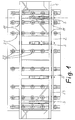
- FIGS 1 to 3 show a plate gripper of a stacking device, the simplicity for the sake of the movable arm of the stacking device and the swiveling device, which connects the arm to the plate gripper are not shown.
- the one shown Plate gripper consists of a suction crossbar 1 and a suction frame 2, the Suction traverse forms the support frame for the suction frame.
- the suction frame 2 is in turn from a number of vertical suction bars 21, each in turn a number of suction cups 22 and in their lower area by a cross bar 23 with each other are connected.
- the suction frame 2 is guided so that it can move vertically in the suction traverse 1, by the suction beam 21 in each of the upper and lower guides 11 of the suction crossmember are led.
- the suction crossbar 1 is over the horizontal length distributed and arranged between individual suction beams 21 lowering elements 3, which in the Suction cross member 1 are mounted and on which the crossbar 23 of the suction frame 2 below is hung.
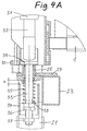
- a lowering element 3 is shown in the enlarged section according to FIG. 3 partly shown in side view and in section IV in section.
- the figures 4A and 4B show enlarged the construction and the function of the detail IV in Figure 3. These are explained in more detail below.
- FIGS. 4A and 4B show fragments of the suction traverse 1 and one each lowering member 3 mounted therein. Also in these figures are fragments of the relative to the Suction cross-member 1 movable suction frame 2 visible, namely all the suction beams with each other connecting crossbar 23 and one of the suction beams 21.
- the crossbar 23 is in Area of each lowering member 3 with a plate 24 and a sleeve 25 firmly connected thus also embody parts of the suction frame 2 which is movable relative to the suction crossmember 1.
- Each lowering member consists of an electric cylinder 31 with a stroke of, for example about 200 mm.
- the lifting spindle 32 of each electric cylinder 31 carries a Rod 33 is a support sleeve 34.
- a strong one Compression spring 35 installed, over which now in the area of the respective lowering member the suction frame 2 over the crossbar 23, the plate 24 and the sleeve 25 on the support sleeve 34 supports.
- the lower region of the rod 33 is designed as a threaded rod and carries two adjusting nuts, namely an upper adjusting nut 36 and a lower adjusting nut 37.
- the lower position nut 37 is the axial position of the support sleeve 34 adjustable on the rod 33, while with the upper adjusting nut 36 the axial position a spring abutment 38 on the rod 33 and thus the bias of the spring 35 is adjustable.
- the springs 35 of all lowering elements are dimensioned and adjusted so that the sum of the Spring pressure forces is slightly less than the weight of the suction frame 2. That has with the result that in the vertical position of the plate gripper, as shown in FIGS. 1 to 3 the weight of the suction frame 2 acting approximately vertically downward is shown just exceeds the spring pressure forces of the compression springs 35 and causes the suction frame 2 compresses these springs, so that on each lowering element 3 Sleeve 25 sits on the support sleeve 24.
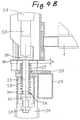
- the plate gripper is now in with the picked up after swiveling Glass plate in the approximately vertical position shown in Figures 2 and 3, added the weight of the glass plate carried also corresponds to the weight of the suction frame 2, and this total weight is much greater than the sum of the compression spring forces Springs 35.
- the suction frame 2 now lowers by the distance x until at each Lowering member 3, the sleeve 25 sits on the support sleeve 24 and now the upper end of the Sleeve 25 a distance x corresponding distance from the head 29 of the respective lifting spindle 32 has. This position is shown in Figure 4B.
- the glass plate When the glass plate is lowered onto the stacking frame, the glass plate is put on with its lower edge surface on the stacking frame "soft" because essentially only that Dead weight of the glass plate and a small proportion of the suction frame weight effective are. Pressing down by the lowering device cannot take place because, as before described the outward movement of the lifting spindles 32 by lifting each sleeve 25 is received by the associated support sleeve 34. After putting on and at the end of the lowering movement, the glass plate is blown off the suction cups, so that it fits onto the glass plate previously placed on the stacking frame, the frame or spacer bars.
- the glass plates are stacked in the following way:
- the electric cylinders are fully retracted, and the plate gripper moves the glass plate over the stacking rack until the bottom edge the glass plate is about 80 mm above the frame contact areas. Then be actuated the electric cylinders to lower the glass plate. When sitting on the glass plate the current extension position on the frame will automatically change when the electric cylinder stops saved.
- the electric cylinders then move back into the to hold the next glass plate Home position.
- they move Electric cylinders in each case the same as those saved in the previous settling process Position minus a distance of about 10 to 20 mm, so that the final Lowering movement is only about 10 to 20 mm.
Abstract
Description
- Fig. 1
- In Rückansicht einen Plattengreifer einer Stapelvorrichtung mit einer abzusetzenden Glasplatte,
- Fig. 2
- eine Seitenansicht der in Figur 1 gezeigten Anordnung mit einem strichpunktiert angedeuteten Stapelgestell,
- Fig. 3
- in vergrößerter Darstellung einen Schnitt längs der Linie III-III in Figur 1
- Fig. 4A
- die Einzelheit IV in Fig. 3 in einer ersten Betriebsstellung (vor Aufnehmen der Glasplatte), und
- Fig. 4B
- die Einzelheit IV in Figur 3 in weiter vergrößerter Darstellung in einer zweiten Betriebsposition (nach Aufnehmen der Glasplatte).
Claims (8)
- Einrichtung zum Absenken von Glasplatten auf Stapelgestelle, die zwischen der Saugtraverse (1) eines Plattengreifers und dem von diesem getragenen und relativ dazu vertikal beweglich geführten Saugrahmen (2) angeordnet ist und mindestens ein Absenkorgan (3) umfaßt, mit folgenden Merkmalen:a) jedes Absenkorgan (3) weist ein ausfahrbares Hubelement (32) auf, das an seinem freien Ende ein Tragelement (34) zum Abstützen des Saugrahmens (2) aufweist,b) der Saugrahmen ist um eine gewisse kurze Distanz (x) vertikal beweglich am Hubelement (32) gehaltert,c) zwischen dem Tragelement (34) und dem Saugrahmen (2) ist eine Druckfeder eingebaut, wobei die Summe der Federkräfte der Druckfedern aller vorhandenen Absenkorgane (3) größer als das Eigengewicht des Saugrahmens ist,d) die vertikale Bewegungsdistanz (x) zwischen dem Saugrahmen (2) und dem Hubelement (32) wird durch einen oberen Anschlage zwischen dem Hubelement und dem Saugrahmen und einen unteren Anschlag zwischen dem Saugrahmen und dem oberen Ende des Tragelements (34) festgelegt ist, auf welchem der Saugrahmen unter teilweisem Zusammendrücken der Druckfeder (35) aufsitzen kann.
- Einrichtung nach Anspruch 1, wobei jedes Huborgan durch einen Elektrozylinder (31) mit Hubspindel (32) gebildet ist.
- Einrichtung nach Anspruch 1 oder 2, wobei die mögliche Bewegungsdistanz (x) zwischen dem Hubelement (32) und dem Saugrahmen (2) durch Einstellbarkeit (36) der Axialposition des Tragelements (34) am freien Ende des Hubelements (32) einstellbar ist.
- Einrichtung nach einem der Ansprüche 1 bis 3, wobei die Federkraft der Druckfeder (35) durch axiale Verstellbarkeit (37) eines Federanschlags (38) verstellbar ist.
- Einrichtung nach einem der Ansprüche 1 bis 4, wobei das freie untere Ende des Hubelements (32) durch eine Tragstange (33) gebildet ist, an deren unterem Ende das hülsenförmige oder becherförmige Tragelement (34) montiert ist und auf welcher die Druckfeder (35) als Spiralfeder angeordnet ist.
- Einrichtung nach den Ansprüchen 4 und 5, wobei das untere Ende der Tragstange (32) als Gewindestange ausgebildet ist, die innerhalb des hülsen- oder becherförmigen Tragelements (34) eine Einstellmutter (37) zum Einstellen der Axialposition eines Federtellers (38) und unterhalb des Tragelements (34) eine Einstellmutter (37) zum Einstellen des Axialposition des Tragelements (34) aufweist.
- Einrichtung nach einem der Ansprüche 1 bis 6, wobei ein Sensor (30) zum Erfassen einer Relativbewegung zwischen dem Saugrahmen (2) und dem Hubelement (32) vorgesehen ist.
- Einrichtung nach Anspruch 7, wobei der Sensor als Näherungsschalter ausgebildet ist, der ein Abheben des Saugrahmens (2) von der auf dem Tragelement (34) aufsitzenden Position meldet.
Applications Claiming Priority (2)
| Application Number | Priority Date | Filing Date | Title |
|---|---|---|---|
| DE10236775A DE10236775A1 (de) | 2002-08-10 | 2002-08-10 | Einrichtung zum Absenken von Glasplatten auf Stapelgestelle |
| DE10236775 | 2002-08-10 |
Publications (3)
| Publication Number | Publication Date |
|---|---|
| EP1388511A2 true EP1388511A2 (de) | 2004-02-11 |
| EP1388511A3 EP1388511A3 (de) | 2004-08-25 |
| EP1388511B1 EP1388511B1 (de) | 2006-07-12 |
Family
ID=30128822
Family Applications (1)
| Application Number | Title | Priority Date | Filing Date |
|---|---|---|---|
| EP03004574A Expired - Lifetime EP1388511B1 (de) | 2002-08-10 | 2003-02-28 | Einrichtung zum Absenken von Glasplatten auf Stapelgestelle |
Country Status (4)
| Country | Link |
|---|---|
| EP (1) | EP1388511B1 (de) |
| AT (1) | ATE332861T1 (de) |
| DE (2) | DE10236775A1 (de) |
| ES (1) | ES2268183T3 (de) |
Cited By (5)
| Publication number | Priority date | Publication date | Assignee | Title |
|---|---|---|---|---|
| EP1695928A1 (de) * | 2005-02-18 | 2006-08-30 | Alessandro Piazza | Vorrichtung zum Transport von einzelnen und geschichten Scheibenprodukten |
| CN102874598A (zh) * | 2012-09-06 | 2013-01-16 | 东莞市五株电子科技有限公司 | 基板投放方法 |
| WO2014079098A1 (zh) * | 2012-11-23 | 2014-05-30 | 深圳市华星光电技术有限公司 | 面板解包方法及解包装置 |
| CN104097950A (zh) * | 2013-04-08 | 2014-10-15 | 常州亚玛顿股份有限公司 | 玻璃运输装置 |
| CN106629058A (zh) * | 2016-12-07 | 2017-05-10 | 中国建材国际工程集团有限公司 | 从玻璃板下表面抓取玻璃的吸盘装置及控制方法 |
Citations (4)
| Publication number | Priority date | Publication date | Assignee | Title |
|---|---|---|---|---|
| FR2012911A1 (en) * | 1968-07-12 | 1970-03-27 | Werner Joh | Positioning or lifting glass onto a carriage |
| US3679073A (en) * | 1969-02-13 | 1972-07-25 | Saint Gobain | Apparatus for handling fragile sheets |
| DE2357118A1 (de) * | 1973-11-15 | 1975-05-28 | Matthias Dipl Ing Kiwull | Kippbarer tisch mit ablagegestell fuer die aufnahme und weitergabe von platten, insbesondere isolierglasscheiben |
| EP0982251A2 (de) * | 1998-08-24 | 2000-03-01 | FOR.EL. BASE di VIANELLO FORTUNATO & C. S.n.c. | Automatische oder halbautomatische Maschine zum Entnehmen von Glasscheiben oder anderen Materialen von einem Lager und Speisung einer Bearbeitungsmaschine und/oder umgekehrt |
Family Cites Families (1)
| Publication number | Priority date | Publication date | Assignee | Title |
|---|---|---|---|---|
| IT232710Y1 (it) * | 1994-01-27 | 2000-01-19 | Breton Automazioni Spa | Apparecchiatura perfezionata per il carico e lo scarico di lastre di materiale lapideo da una macchina operatrice. |
-
2002
- 2002-08-10 DE DE10236775A patent/DE10236775A1/de not_active Withdrawn
-
2003
- 2003-02-28 EP EP03004574A patent/EP1388511B1/de not_active Expired - Lifetime
- 2003-02-28 AT AT03004574T patent/ATE332861T1/de not_active IP Right Cessation
- 2003-02-28 ES ES03004574T patent/ES2268183T3/es not_active Expired - Lifetime
- 2003-02-28 DE DE50304192T patent/DE50304192D1/de not_active Expired - Lifetime
Patent Citations (4)
| Publication number | Priority date | Publication date | Assignee | Title |
|---|---|---|---|---|
| FR2012911A1 (en) * | 1968-07-12 | 1970-03-27 | Werner Joh | Positioning or lifting glass onto a carriage |
| US3679073A (en) * | 1969-02-13 | 1972-07-25 | Saint Gobain | Apparatus for handling fragile sheets |
| DE2357118A1 (de) * | 1973-11-15 | 1975-05-28 | Matthias Dipl Ing Kiwull | Kippbarer tisch mit ablagegestell fuer die aufnahme und weitergabe von platten, insbesondere isolierglasscheiben |
| EP0982251A2 (de) * | 1998-08-24 | 2000-03-01 | FOR.EL. BASE di VIANELLO FORTUNATO & C. S.n.c. | Automatische oder halbautomatische Maschine zum Entnehmen von Glasscheiben oder anderen Materialen von einem Lager und Speisung einer Bearbeitungsmaschine und/oder umgekehrt |
Cited By (8)
| Publication number | Priority date | Publication date | Assignee | Title |
|---|---|---|---|---|
| EP1695928A1 (de) * | 2005-02-18 | 2006-08-30 | Alessandro Piazza | Vorrichtung zum Transport von einzelnen und geschichten Scheibenprodukten |
| CN102874598A (zh) * | 2012-09-06 | 2013-01-16 | 东莞市五株电子科技有限公司 | 基板投放方法 |
| CN102874598B (zh) * | 2012-09-06 | 2016-04-20 | 东莞市威力固电路板设备有限公司 | 基板投放方法 |
| WO2014079098A1 (zh) * | 2012-11-23 | 2014-05-30 | 深圳市华星光电技术有限公司 | 面板解包方法及解包装置 |
| US9387946B2 (en) | 2012-11-23 | 2016-07-12 | Shenzhen China Star Optoelectronics Technology Co., Ltd | Panel unpacking method and panel unpacking device |
| CN104097950A (zh) * | 2013-04-08 | 2014-10-15 | 常州亚玛顿股份有限公司 | 玻璃运输装置 |
| CN106629058A (zh) * | 2016-12-07 | 2017-05-10 | 中国建材国际工程集团有限公司 | 从玻璃板下表面抓取玻璃的吸盘装置及控制方法 |
| CN106629058B (zh) * | 2016-12-07 | 2023-11-21 | 中国建材国际工程集团有限公司 | 从玻璃板下表面抓取玻璃的吸盘装置及控制方法 |
Also Published As
| Publication number | Publication date |
|---|---|
| EP1388511A3 (de) | 2004-08-25 |
| DE50304192D1 (de) | 2006-08-24 |
| ES2268183T3 (es) | 2007-03-16 |
| EP1388511B1 (de) | 2006-07-12 |
| DE10236775A1 (de) | 2004-02-19 |
| ATE332861T1 (de) | 2006-08-15 |
Similar Documents
| Publication | Publication Date | Title |
|---|---|---|
| EP1724078B1 (de) | Vorrichtung zum Abschieben mindestens eines Teilstapels mit mindestens einem plattenförmigen Werkstück von einem Reststapel | |
| DE3800907C2 (de) | Verfahren zur Entstapelung von Blechen | |
| DE3730126C2 (de) | ||
| CH664127A5 (de) | Vorrichtung zum abtrennen von gruppen bestimmter laenge von einem stapel kontinuierlich zugefuehrter gegenstaende. | |
| CH697146A5 (de) | Greifvorrichtung zur Handhabung von Wafern. | |
| DE2505530C3 (de) | Vorrichtung an kontinuierlich arbeitenden Bogenanlegern zur Kompensation der sich beim Stapelwechsel durch das seitliche Herausziehen des Hilfsstapeltisches auf der Oberseite des HilfsStapels fortschreitend bildenden Absenkung | |
| DE19602297A1 (de) | Verfahren und Vorrichtung zum Vereinzeln von gedruckten Schaltungs-Platinen aus einem Stapel | |
| EP1873095A2 (de) | Vorrichtung zum Separieren, insbesondere Abfördern eines Teilstapels mit mindestens einer grossformatigen Platte von einem Reststapel mit einer Mehrzahl grossformatiger Platten | |
| DE4320397C2 (de) | Einrichtung zum Beschicken von Werkzeugmaschinen | |
| EP1388511B1 (de) | Einrichtung zum Absenken von Glasplatten auf Stapelgestelle | |
| EP2481540B1 (de) | Einrichtung zum Zersägen von zumindest zwei platten- oder plattenstapelförmigen Werkstücken | |
| AT396891B (de) | Einrichtung zum beschicken von aufteilsägeanlagen | |
| WO2018166604A1 (de) | Zentriervorrichtung | |
| DE202005014323U1 (de) | Vorrichtung zum Stapeln von Dachpfannen | |
| DE4401510C2 (de) | Vorrichtung zur Bildung eines Stapels aus aneinanderlehnenden, hochkantstehenden Platten | |
| AT331721B (de) | Einrichtung zur aufnahme und weitergabe bzw. zum abstapeln plattenformiger werkstucke | |
| DE2852957A1 (de) | Vorrichtung zum selbsttaetigen stapeln von werkstuecken | |
| CH672284A5 (de) | ||
| DE2505282A1 (de) | Vorrichtung zum vereinzeln von aufgestauten foerderlingen | |
| DE102018123907B4 (de) | Vorrichtung zum Abheben eines plattenförmigen obersten Werkstücks von einem Werkstückstapel | |
| DE3150045A1 (de) | Zufuehreinrichtung fuer blechstreifenstapel zur zufuhr zu einem stanzautomaten | |
| DE1249167B (de) | ||
| EP0591967B1 (de) | Vorrichtung zur Handhabung von Lasten | |
| DE1531040C (de) | Verschiebetisch fur Palettenbelader | |
| EP0162040A2 (de) | Vorrichtung zum Verbinden von aneinander anliegenden Balken od. dgl. mittels Nagelplatten |
Legal Events
| Date | Code | Title | Description |
|---|---|---|---|
| PUAI | Public reference made under article 153(3) epc to a published international application that has entered the european phase |
Free format text: ORIGINAL CODE: 0009012 |
|
| AK | Designated contracting states |
Kind code of ref document: A2 Designated state(s): AT BE BG CH CY CZ DE DK EE ES FI FR GB GR HU IE IT LI LU MC NL PT SE SI SK TR |
|
| AX | Request for extension of the european patent |
Extension state: AL LT LV MK RO |
|
| PUAL | Search report despatched |
Free format text: ORIGINAL CODE: 0009013 |
|
| AK | Designated contracting states |
Kind code of ref document: A3 Designated state(s): AT BE BG CH CY CZ DE DK EE ES FI FR GB GR HU IE IT LI LU MC NL PT SE SI SK TR |
|
| AX | Request for extension of the european patent |
Extension state: AL LT LV MK RO |
|
| 17P | Request for examination filed |
Effective date: 20050216 |
|
| AKX | Designation fees paid |
Designated state(s): AT BE BG CH CY CZ DE DK EE ES FI FR GB GR HU IE IT LI LU MC NL PT SE SI SK TR |
|
| 17Q | First examination report despatched |
Effective date: 20050620 |
|
| GRAP | Despatch of communication of intention to grant a patent |
Free format text: ORIGINAL CODE: EPIDOSNIGR1 |
|
| GRAS | Grant fee paid |
Free format text: ORIGINAL CODE: EPIDOSNIGR3 |
|
| GRAA | (expected) grant |
Free format text: ORIGINAL CODE: 0009210 |
|
| AK | Designated contracting states |
Kind code of ref document: B1 Designated state(s): AT BE BG CH CY CZ DE DK EE ES FI FR GB GR HU IE IT LI LU MC NL PT SE SI SK TR |
|
| PG25 | Lapsed in a contracting state [announced via postgrant information from national office to epo] |
Ref country code: SI Free format text: LAPSE BECAUSE OF FAILURE TO SUBMIT A TRANSLATION OF THE DESCRIPTION OR TO PAY THE FEE WITHIN THE PRESCRIBED TIME-LIMIT Effective date: 20060712 Ref country code: IT Free format text: LAPSE BECAUSE OF FAILURE TO SUBMIT A TRANSLATION OF THE DESCRIPTION OR TO PAY THE FEE WITHIN THE PRESCRIBED TIME-LIMIT;WARNING: LAPSES OF ITALIAN PATENTS WITH EFFECTIVE DATE BEFORE 2007 MAY HAVE OCCURRED AT ANY TIME BEFORE 2007. THE CORRECT EFFECTIVE DATE MAY BE DIFFERENT FROM THE ONE RECORDED. Effective date: 20060712 Ref country code: NL Free format text: LAPSE BECAUSE OF FAILURE TO SUBMIT A TRANSLATION OF THE DESCRIPTION OR TO PAY THE FEE WITHIN THE PRESCRIBED TIME-LIMIT Effective date: 20060712 Ref country code: IE Free format text: LAPSE BECAUSE OF FAILURE TO SUBMIT A TRANSLATION OF THE DESCRIPTION OR TO PAY THE FEE WITHIN THE PRESCRIBED TIME-LIMIT Effective date: 20060712 Ref country code: SK Free format text: LAPSE BECAUSE OF FAILURE TO SUBMIT A TRANSLATION OF THE DESCRIPTION OR TO PAY THE FEE WITHIN THE PRESCRIBED TIME-LIMIT Effective date: 20060712 Ref country code: FI Free format text: LAPSE BECAUSE OF FAILURE TO SUBMIT A TRANSLATION OF THE DESCRIPTION OR TO PAY THE FEE WITHIN THE PRESCRIBED TIME-LIMIT Effective date: 20060712 |
|
| REG | Reference to a national code |
Ref country code: GB Ref legal event code: FG4D Free format text: NOT ENGLISH |
|
| REG | Reference to a national code |
Ref country code: CH Ref legal event code: EP |
|
| REG | Reference to a national code |
Ref country code: IE Ref legal event code: FG4D Free format text: LANGUAGE OF EP DOCUMENT: GERMAN |
|
| REF | Corresponds to: |
Ref document number: 50304192 Country of ref document: DE Date of ref document: 20060824 Kind code of ref document: P |
|
| GBT | Gb: translation of ep patent filed (gb section 77(6)(a)/1977) |
Effective date: 20060830 |
|
| PG25 | Lapsed in a contracting state [announced via postgrant information from national office to epo] |
Ref country code: BG Free format text: LAPSE BECAUSE OF FAILURE TO SUBMIT A TRANSLATION OF THE DESCRIPTION OR TO PAY THE FEE WITHIN THE PRESCRIBED TIME-LIMIT Effective date: 20061012 Ref country code: DK Free format text: LAPSE BECAUSE OF FAILURE TO SUBMIT A TRANSLATION OF THE DESCRIPTION OR TO PAY THE FEE WITHIN THE PRESCRIBED TIME-LIMIT Effective date: 20061012 |
|
| REG | Reference to a national code |
Ref country code: SE Ref legal event code: TRGR |
|
| PG25 | Lapsed in a contracting state [announced via postgrant information from national office to epo] |
Ref country code: PT Free format text: LAPSE BECAUSE OF FAILURE TO SUBMIT A TRANSLATION OF THE DESCRIPTION OR TO PAY THE FEE WITHIN THE PRESCRIBED TIME-LIMIT Effective date: 20061212 |
|
| NLV1 | Nl: lapsed or annulled due to failure to fulfill the requirements of art. 29p and 29m of the patents act | ||
| ET | Fr: translation filed | ||
| REG | Reference to a national code |
Ref country code: IE Ref legal event code: FD4D |
|
| PG25 | Lapsed in a contracting state [announced via postgrant information from national office to epo] |
Ref country code: MC Free format text: LAPSE BECAUSE OF NON-PAYMENT OF DUE FEES Effective date: 20070228 Ref country code: LI Free format text: LAPSE BECAUSE OF NON-PAYMENT OF DUE FEES Effective date: 20070228 Ref country code: CH Free format text: LAPSE BECAUSE OF NON-PAYMENT OF DUE FEES Effective date: 20070228 |
|
| REG | Reference to a national code |
Ref country code: ES Ref legal event code: FG2A Ref document number: 2268183 Country of ref document: ES Kind code of ref document: T3 |
|
| PLBE | No opposition filed within time limit |
Free format text: ORIGINAL CODE: 0009261 |
|
| STAA | Information on the status of an ep patent application or granted ep patent |
Free format text: STATUS: NO OPPOSITION FILED WITHIN TIME LIMIT |
|
| 26N | No opposition filed |
Effective date: 20070413 |
|
| REG | Reference to a national code |
Ref country code: CH Ref legal event code: PL |
|
| PG25 | Lapsed in a contracting state [announced via postgrant information from national office to epo] |
Ref country code: GR Free format text: LAPSE BECAUSE OF FAILURE TO SUBMIT A TRANSLATION OF THE DESCRIPTION OR TO PAY THE FEE WITHIN THE PRESCRIBED TIME-LIMIT Effective date: 20061013 |
|
| PG25 | Lapsed in a contracting state [announced via postgrant information from national office to epo] |
Ref country code: AT Free format text: LAPSE BECAUSE OF NON-PAYMENT OF DUE FEES Effective date: 20070228 |
|
| PG25 | Lapsed in a contracting state [announced via postgrant information from national office to epo] |
Ref country code: EE Free format text: LAPSE BECAUSE OF FAILURE TO SUBMIT A TRANSLATION OF THE DESCRIPTION OR TO PAY THE FEE WITHIN THE PRESCRIBED TIME-LIMIT Effective date: 20060712 |
|
| PG25 | Lapsed in a contracting state [announced via postgrant information from national office to epo] |
Ref country code: CY Free format text: LAPSE BECAUSE OF FAILURE TO SUBMIT A TRANSLATION OF THE DESCRIPTION OR TO PAY THE FEE WITHIN THE PRESCRIBED TIME-LIMIT Effective date: 20060712 |
|
| PG25 | Lapsed in a contracting state [announced via postgrant information from national office to epo] |
Ref country code: HU Free format text: LAPSE BECAUSE OF FAILURE TO SUBMIT A TRANSLATION OF THE DESCRIPTION OR TO PAY THE FEE WITHIN THE PRESCRIBED TIME-LIMIT Effective date: 20070113 Ref country code: TR Free format text: LAPSE BECAUSE OF FAILURE TO SUBMIT A TRANSLATION OF THE DESCRIPTION OR TO PAY THE FEE WITHIN THE PRESCRIBED TIME-LIMIT Effective date: 20060712 |
|
| REG | Reference to a national code |
Ref country code: FR Ref legal event code: PLFP Year of fee payment: 14 |
|
| REG | Reference to a national code |
Ref country code: FR Ref legal event code: PLFP Year of fee payment: 15 |
|
| REG | Reference to a national code |
Ref country code: FR Ref legal event code: PLFP Year of fee payment: 16 |
|
| PGFP | Annual fee paid to national office [announced via postgrant information from national office to epo] |
Ref country code: GB Payment date: 20220221 Year of fee payment: 20 Ref country code: DE Payment date: 20220217 Year of fee payment: 20 |
|
| PGFP | Annual fee paid to national office [announced via postgrant information from national office to epo] |
Ref country code: SE Payment date: 20220221 Year of fee payment: 20 Ref country code: LU Payment date: 20220214 Year of fee payment: 20 Ref country code: IT Payment date: 20220228 Year of fee payment: 20 Ref country code: FR Payment date: 20220221 Year of fee payment: 20 Ref country code: ES Payment date: 20220318 Year of fee payment: 20 Ref country code: CZ Payment date: 20220228 Year of fee payment: 20 Ref country code: BE Payment date: 20220216 Year of fee payment: 20 |
|
| REG | Reference to a national code |
Ref country code: DE Ref legal event code: R082 Ref document number: 50304192 Country of ref document: DE Representative=s name: FLEUCHAUS & GALLO PARTNERSCHAFT MBB PATENTANWA, DE |
|
| REG | Reference to a national code |
Ref country code: DE Ref legal event code: R071 Ref document number: 50304192 Country of ref document: DE |
|
| REG | Reference to a national code |
Ref country code: BE Ref legal event code: MK Effective date: 20230228 |
|
| REG | Reference to a national code |
Ref country code: GB Ref legal event code: PE20 Expiry date: 20230227 |
|
| REG | Reference to a national code |
Ref country code: SE Ref legal event code: EUG |
|
| PG25 | Lapsed in a contracting state [announced via postgrant information from national office to epo] |
Ref country code: CZ Free format text: LAPSE BECAUSE OF EXPIRATION OF PROTECTION Effective date: 20230228 |
|
| REG | Reference to a national code |
Ref country code: ES Ref legal event code: FD2A Effective date: 20230428 |
|
| PG25 | Lapsed in a contracting state [announced via postgrant information from national office to epo] |
Ref country code: GB Free format text: LAPSE BECAUSE OF EXPIRATION OF PROTECTION Effective date: 20230227 |
|
| PG25 | Lapsed in a contracting state [announced via postgrant information from national office to epo] |
Ref country code: ES Free format text: LAPSE BECAUSE OF EXPIRATION OF PROTECTION Effective date: 20230301 |