EP1385330A2 - Messverfahren und -gerät für die Druckqualität - Google Patents
Messverfahren und -gerät für die Druckqualität Download PDFInfo
- Publication number
- EP1385330A2 EP1385330A2 EP03015450A EP03015450A EP1385330A2 EP 1385330 A2 EP1385330 A2 EP 1385330A2 EP 03015450 A EP03015450 A EP 03015450A EP 03015450 A EP03015450 A EP 03015450A EP 1385330 A2 EP1385330 A2 EP 1385330A2
- Authority
- EP
- European Patent Office
- Prior art keywords
- color
- image
- data
- positions
- Prior art date
- Legal status (The legal status is an assumption and is not a legal conclusion. Google has not performed a legal analysis and makes no representation as to the accuracy of the status listed.)
- Granted
Links
- 238000000034 method Methods 0.000 title claims description 35
- 238000004364 calculation method Methods 0.000 claims abstract description 39
- 230000000052 comparative effect Effects 0.000 claims abstract description 37
- 239000000976 ink Substances 0.000 description 36
- 230000015654 memory Effects 0.000 description 8
- 238000006243 chemical reaction Methods 0.000 description 2
- 238000010586 diagram Methods 0.000 description 2
- 238000005070 sampling Methods 0.000 description 2
- 238000003491 array Methods 0.000 description 1
- 238000010276 construction Methods 0.000 description 1
- 230000005611 electricity Effects 0.000 description 1
- 238000012905 input function Methods 0.000 description 1
- 230000010354 integration Effects 0.000 description 1
- 238000004519 manufacturing process Methods 0.000 description 1
- 230000003068 static effect Effects 0.000 description 1
Images


Classifications
-
- H—ELECTRICITY
- H04—ELECTRIC COMMUNICATION TECHNIQUE
- H04N—PICTORIAL COMMUNICATION, e.g. TELEVISION
- H04N1/00—Scanning, transmission or reproduction of documents or the like, e.g. facsimile transmission; Details thereof
- H04N1/46—Colour picture communication systems
- H04N1/56—Processing of colour picture signals
- H04N1/60—Colour correction or control
- H04N1/603—Colour correction or control controlled by characteristics of the picture signal generator or the picture reproducer
- H04N1/6033—Colour correction or control controlled by characteristics of the picture signal generator or the picture reproducer using test pattern analysis
-
- B—PERFORMING OPERATIONS; TRANSPORTING
- B41—PRINTING; LINING MACHINES; TYPEWRITERS; STAMPS
- B41F—PRINTING MACHINES OR PRESSES
- B41F33/00—Indicating, counting, warning, control or safety devices
- B41F33/0036—Devices for scanning or checking the printed matter for quality control
-
- H—ELECTRICITY
- H04—ELECTRIC COMMUNICATION TECHNIQUE
- H04N—PICTORIAL COMMUNICATION, e.g. TELEVISION
- H04N1/00—Scanning, transmission or reproduction of documents or the like, e.g. facsimile transmission; Details thereof
- H04N1/00002—Diagnosis, testing or measuring; Detecting, analysing or monitoring not otherwise provided for
- H04N1/00007—Diagnosis, testing or measuring; Detecting, analysing or monitoring not otherwise provided for relating to particular apparatus or devices
- H04N1/00023—Colour systems
-
- H—ELECTRICITY
- H04—ELECTRIC COMMUNICATION TECHNIQUE
- H04N—PICTORIAL COMMUNICATION, e.g. TELEVISION
- H04N1/00—Scanning, transmission or reproduction of documents or the like, e.g. facsimile transmission; Details thereof
- H04N1/00002—Diagnosis, testing or measuring; Detecting, analysing or monitoring not otherwise provided for
- H04N1/00026—Methods therefor
- H04N1/00045—Methods therefor using a reference pattern designed for the purpose, e.g. a test chart
-
- H—ELECTRICITY
- H04—ELECTRIC COMMUNICATION TECHNIQUE
- H04N—PICTORIAL COMMUNICATION, e.g. TELEVISION
- H04N1/00—Scanning, transmission or reproduction of documents or the like, e.g. facsimile transmission; Details thereof
- H04N1/00002—Diagnosis, testing or measuring; Detecting, analysing or monitoring not otherwise provided for
- H04N1/00026—Methods therefor
- H04N1/00055—Methods therefor automatically on a periodic basis
-
- H—ELECTRICITY
- H04—ELECTRIC COMMUNICATION TECHNIQUE
- H04N—PICTORIAL COMMUNICATION, e.g. TELEVISION
- H04N1/00—Scanning, transmission or reproduction of documents or the like, e.g. facsimile transmission; Details thereof
- H04N1/00002—Diagnosis, testing or measuring; Detecting, analysing or monitoring not otherwise provided for
- H04N1/00071—Diagnosis, testing or measuring; Detecting, analysing or monitoring not otherwise provided for characterised by the action taken
- H04N1/00082—Adjusting or controlling
- H04N1/00084—Recovery or repair, e.g. self-repair
-
- H—ELECTRICITY
- H04—ELECTRIC COMMUNICATION TECHNIQUE
- H04N—PICTORIAL COMMUNICATION, e.g. TELEVISION
- H04N1/00—Scanning, transmission or reproduction of documents or the like, e.g. facsimile transmission; Details thereof
- H04N1/00002—Diagnosis, testing or measuring; Detecting, analysing or monitoring not otherwise provided for
- H04N1/00071—Diagnosis, testing or measuring; Detecting, analysing or monitoring not otherwise provided for characterised by the action taken
- H04N1/00082—Adjusting or controlling
- H04N1/00087—Setting or calibrating
Definitions
- This invention relates to print quality measuring methods and print quality measuring apparatus.
- a print quality measuring apparatus which provides control data for controlling the ink feeding rates of a printing machine.
- the control data is produced by comparing an image on reference paper and an image on an actual print.
- the reference paper is also called proof paper, and serves as a reference indicating a color tone of finished prints to obtain proper prints.
- Printing paper actually printed is also called sampling paper which is extracted by the operator from a discharge station of a printing machine at certain intervals during a printing operation. The printing is considered proper when the color tone on the sampling paper substantially coincides with the color tone on the reference paper.
- the object of this invention is to provide a print quality measuring method and a print quality measuring apparatus for forming proper images in areas characterizing a picture, thereby obtaining proper prints from a printing machine.
- a print quality measuring method for comparing an image of reference paper and an image of an actual print to create control data for controlling ink feeding rates of a printing machine, the method comprising a reading step for reading the image of the reference paper and the image of the actual print; a representative color determining step for determining, from image data, a representative color characterizing the image of the print, and positions of the representative color; and a calculating step for carrying out a comparative calculation of color data in the positions of the representative color of the image of the reference paper and color data in the positions of the representative color of the image of the print, to create the control data for controlling the ink feeding rates of the printing machine.
- proper images may be formed in areas characterizing a picture, thereby obtaining proper prints from a printing machine.
- the representative color and the positions thereof are determined for respective sections corresponding to ink keys in each ink well of the printing machine.
- the image data has three color components, the representative color determining step being executed to classify pixels in each of the sections corresponding to ink keys, and determine the representative color and a position thereof from pixels included in a predetermined class interval.
- the representative color determining step may be executed to create a histogram with tones of each of the three color components of each pixel in each of the sections, and select the representative color and the position thereof from pixels included in a class interval of maximum frequency in the histogram.
- the print quality measuring method further comprises a gray control color determining step for determining, from the image data, a gray control color expressed in a substantially achromatic color and positions of the gray control color; wherein the operating step is executed to create the control data for controlling the ink feeding rates of the printing machine, by using results of a comparative calculation of color data in the positions of the gray control color of the image of the reference paper and color data in the positions of the gray control color of the image of the print, as well as results of the comparative calculation of the color data in the positions of the representative color of the image of the reference paper and the color data in the positions of the representative color of the image of the print.
- a print quality measuring method for comparing image data obtained by reading an image of an actual print with one of platemaking data used at platemaking time and image data created from the platemaking data, to create control data for controlling ink feeding rates of a printing machine, the method comprising a reading step for reading the image of the actual print; a representative color determining step for determining a representative color characterizing the image of the print, and positions of the representative color, based on one of the platemaking data used at platemaking time and the image data created from the platemaking data; and a calculating step for carrying out a comparative calculation of color data in the positions of the representative color of the image of the print and the representative color, to create the control data for controlling the ink feeding rates of the printing machine.
- a print quality measuring apparatus for comparing an image of reference paper and an image of an actual print to create control data for controlling ink feeding rates of a printing machine, the apparatus comprising a reading unit for reading the image of the reference paper and the image of the actual prints a representative color determining unit for determining, from image data, a representative color characterizing the image of the print, and positions of the representative color; and a calculating unit for carrying out a comparative calculation of color data in the positions of the representative color of the image of the reference paper and color data in the positions of the representative color of the image of the print, to create the control data for controlling the ink feeding rates of the printing machine.
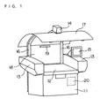
- Fig. 1 is a perspective view of a print quality measuring apparatus according to the invention.
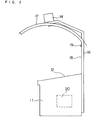
- Fig. 2 is a side view of the apparatus. It is to be noted that light sources 13 and a control panel 15 are omitted from Fig. 2.
- This print quality measuring apparatus includes a table 12 disposed above a frame 11, a pair of light sources 13 arranged at right and left sides of the table 12, an image pickup unit 14 disposed above the table 12, a control panel 15 disposed above one of the light sources 13, an upper light-shielding plate 17 and a rear light-shielding plate 18 supported by a pair of posts 16, an auxiliary light source 19 attached to the rear light-shielding plate 18, and a control unit 20 mounted inside the frame 11 for controlling the entire apparatus.
- the table 12 is shaped planar for receiving a print thereon.
- the table 12 has a surface in the form of a suction plate for holding the print by static electricity or vacuum suction.
- the surface of the table 12 is inclined about 10 degrees for facility of operation by the operator.
- the print held by suction on the inclined surface of the table 12 is illuminated by the pair of light sources 13 arranged at the opposite sides.
- the image pickup unit 14 disposed above the table 12 has a digital camera for separating, with a dichroic mirror, light emitted from the light sources 13 and reflected from the surface of the print into the three primary color components of RGB, and receiving the individual components with separate CCD arrays. With this image pickup unit 14, RGB data can be obtained from the print.
- the control panel 15 is the touch panel type in the form of an LCD monitor having a pressure sensitive input function (also called a touch sensitive screen). This control panel 15 acts as both a display device and an input device, and is connected to the control unit 20 described hereinafter.
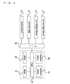
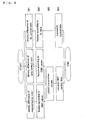
- Fig. 3 is a block diagram showing a principal structure of the control unit 20.
- This control unit 20 includes a ROM 21 for storing operating programs necessary for controlling the apparatus, a RAM 22 for temporarily storing data and the like during a control operation, a CPU 23 for performing logic operations, and a first and a second image memories 24 and 25.
- the control unit 20 is connected through an interface 26 to the control panel 15, light sources 13 and image pickup unit 14 noted above.
- the control unit 20 is connected also to an image data source 27 storing image data to be printed, such as a hard disk or an image processing device.
- This control unit 20 acts as the representative color determining device, gray control color determining device and calculating device of this invention.
- the upper light-shielding plate 17 supported by the pair of posts 16 has a curved configuration extending in the fore and aft direction of the print quality measuring apparatus.
- the light-shielding plate 17 is installed in order to intercept light, such as light from indoor light sources, that would constitute a regular reflection from the table 12.
- the rear light-shielding plate 18 supported between the pair of posts 16 serves to intercept light coming from behind the print quality measuring apparatus.
- the auxiliary light source 19 attached to the rear light-shielding plate 18 serves to compensate for a lack of light on the table 12 caused by the upper light-shielding plate 17 and rear light-shielding plate 18.
- the auxiliary light source 19 is in the form of a fluorescent light or the like, which is turned off when reading a print with the image pickup unit 14.
- a representative color determining and other steps described in detail hereinafter are first executed by using image data stored in the image data source 27 of an image to be printed.
- reading steps are executed to read an image of reference paper and an image actually printed.
- reference paper is first placed on the table 12 and held thereon by suction.
- the reference paper is illuminated by the light sources 13, and the image of the reference paper is read by the image pickup unit 14.
- Data of the image of the reference paper is stored in the first image memory 24 of the control unit 20.
- a print extracted by the operator from a discharge station of a printing machine during a printing operation is placed on the table 12, and held thereon by suction. This print is illuminated by the light sources 13, and the image of the print is read by the image pickup unit 14.
- Data of the image of the print is stored in the second image memory 25 of the control unit 20.
- control data for controlling ink feeding rates of the printing machine.
- This control data is transmitted on-line or off-line through the interface 26 to the printing machine not shown.
- Fig. 4 is a flow chart of the print quality measuring operation.
- step S1 When a print is measured in order to create the control data for controlling the ink feeding rates of the printing machine, a representative color characterizing the image to be printed and positions of this color are first determined based on the data of the image (step S1). This representative color determining step is executed by a subroutine shown in Fig. 5.
- the image data of the image to be printed is fetched from the image data source 27 (step S11).
- This image data is platemaking data of CMYK (cyan, magenta, yellow and black) for an image printed when making printing plates, or image data created from this platemaking data.
- This image data is supplied as PPF (Print Production Format) data, for example, according to the CIP3 (international Cooperation for Integration of Prepress, Press and Postpress) standards.
- PPF Print Production Format
- CIP3 international Cooperation for Integration of Prepress, Press and Postpress
- black is referred to as K or Bk as appropriate.
- this PPF data (CMYK data) is converted to data with RGB tones (step S12).
- the conversion is performed by the formulas (1) - (3) set out below.
- Negative RGB values are regarded as zero.
- R 255 - (C+K)
- G 255-(M+K)
- B 255 - (Y+K)
- edge components are extracted and removed from the RGB image (step S13). That is, when an edge amount which is a sum of differences (absolute values) between a given pixel and pixels adjacent thereto in the four directions exceeds a fixed value, this given pixel is regarded as an edge pixel. Such edge pixels are excluded from the subsequent process.
- the RGB image is divided into sections corresponding to ink keys in each ink well of the printing machine (step S14).
- the subsequent steps are executed for each divided section.
- pixels with heavy contributions of Bk (black) ink are extracted and removed (step S15). That is, of the data of CMYK before conversion to RGB, pixels with a minimum value of CMY smaller than the value of K are regarded as pixels with heavy contributions of Bk, and are excluded from the subsequent process.
- a three-dimensional histogram is created with the RGB values of the remaining pixels (step S16). Specifically, a three-dimensional region is appropriately divided for every color component of RGB to form equally divided cubes with one side including a predetermined tonal range, and then a frequency distribution is determined for respective class intervals.
- a process of creating this three-dimensional histogram is described in detail in Japanese Unexamined Patent Publication No. 11-296672 (1999) in the name of Assignee herein.
- the histogram is created with the RGB values.
- a frequency distribution may be created with three components of a different color system, such as CMY values.
- a color expressed by the intervals of the histogram is weighted by multiplying the frequency by an appropriate factor (step S17).
- an appropriate factor When it is desired to give priority to flesh color in the picture as representative color, its color gamut is multiplied by a large factor.
- An interval having a maximum frequency after the multiplication by the factor is determined to be the color gamut serving as representative color, and only the pixels included in this interval are considered in the subsequent process.
- a histogram is created to determine a color gamut serving as representative color.
- the operator may designate a predetermined color gamut in place of the interval having the maximum frequency. In this case, the calculation of frequencies is unnecessary.
- isolated points are removed from the pixels included in the interval of maximum frequency resulting from the multiplication (step S18). That is, outermost pixels of the areas formed by the pixels included in the interval of maximum frequency resulting from the multiplication are removed as isolated points. This operation is repeated until the total number of pixels in all areas becomes 1 or 0 (step S19).
- the CMYK values of this pixel is regarded as forming the representative color, and the position of the pixel is regarded as the position of the representative color.
- the CMYK values of one of the pixels that remained to the last e.g. a pixel near the center of the sections corresponding to the ink keys, are regarded as forming the representative color, and the position of this pixel is regarded as the position of the representative color. In this way, a representative color and its position are determined (step S20).
- the position of maximum area formed by the pixels (area of a series of pixels) included in the interval of maximum frequency after the removal of isolated points is selected to be the position of representative color as noted above. This is done to avoid the influence of errors caused by the intrinsic noise of the image pickup unit 14, and the influence of alignment errors occurring when comparing color data of a position of a representative color of the image on the reference paper described hereinafter and color data of the position of the representative color of a printed image.
- one pixel remaining after the removal of isolated points is regarded as the pixel corresponding to the representative color, and the CMYK values of this pixel are regarded as forming the representative color.
- the representative color may be obtained from an average or weighted average of the CMYK values of that pixel and a number of adjacent pixels. This measure is effective for lessening the influence of noise included in pixels.
- a gray control color expressed in a substantially achromatic color and its position are determined next (step S2).
- This gray control color determining step is executed by a sequence similar to that of the representative color determining step shown in Fig. 5. However, in the gray control color determining step, step S17 in Fig. 5 is executed to multiply the intervals of the histogram corresponding to gray by a factor of 1 or more, so that a gray portion is selected with priority in step S18.
- a predetermined color gamut may be designated directly as an interval presenting the gray control color.
- step S3 a Bk control color expressed in black and its positions are determined.
- This Bk control color determining step is executed by a sequence similar to that of the representative color determining step shown in Fig. 5. However, in the gray control color determining step, step S15 in Fig. 5 is executed to extract and remove pixels with minor contributions of Bk (black) ink. That is, of the CMYK data, the pixels with a maximum value of CMY larger than the value of K are regarded as pixels with minor contributions of Bk, and are excluded from the subsequent process.
- the selected Bk region fails to have a fixed area, that is when the number of repetitions made in step S19 does not reach a fixed number, the section corresponding to one of the ink keys are regarded as being smaller than a predetermined Bk area, and no Bk control color is determined.
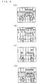
- Fig. 6 shows explanatory views showing positions of the representative color, gray control color and Bk control color.
- D1-D7 denote positions of the representative color determined in the representative color determining step (step S1).
- G1-G7 denote positions of the gray control color determined in the gray control color determining step (step S2).
- B2 and B6 denote positions of the Bk control color obtained in the Bk color determining step (step S3).
- the positions of the representative color, gray control color and Bk control color are displayed, along with the image to be printed, on the control panel 15 shown in Fig. 1.
- the operator may confirm the positions of the gray control color and Bk control color displayed on the control panel 15, and may, as necessary, change the positions of the representative color as shown in Fig. 6 (d).
- the image is divided into seven sections corresponding to the ink keys in each ink well of the printing machine. Further, in this embodiment, Bk control points are present only in the second section from the right and in the second section from the left.
- step S4 and S5 the image of the reference paper and the image of an actual print are read (steps S4 and S5).
- the image of reference paper S1 is first read by the image pickup unit 14.
- the RGB values and positions of the representative color, the RGB values and positions of the gray control color and the RGB values and positions of the Bk control color are stored in the first image memory 24 shown in Fig. 3.
- an image 100 acquired from the image data and an image 101 read by the image pickup unit 14 are different from each other in the number of the pixels, resolution, margin and so on. It is therefore necessary to correlate the two images in order to obtain correctly the RGB values and positions of the representative color, the RGB values and positions of the gray control color and the RGB values and positions of the Bk control color.
- the images may be displayed on the control panel 15 for the operator to work with the images manually or carry out a pattern matching.
- An example of pattern matching techniques is disclosed in Japanese Patent Application No. 2002-205117 in the name of Assignee herein.
- the image of actual print S2 is read by the image pickup unit 14.
- positions corresponding to the positions of the representative color, gray control color and Bk control color derived from the PPF data are determined.
- the RGB values and positions of the representative color, the RGB values and positions of the gray control color and the RGB values and positions of the Bk control color are stored in the second image memory 25 shown in Fig. 3.
- an image 100 acquired from the image data and an image 101 read by the image pickup unit 14 are different from each other in the number of the pixels, resolution, margin and so on.
- the images may be displayed on the control panel 15 for the operator to work with the images manually or carry out a pattern matching.
- step S6 a comparative calculation is carried out on the data obtained by reading the image of the reference paper and the image of the actual print, to create control data for controlling the ink feeding rates of the printing machine.
- This calculating step is executed by a subroutine shown in Fig. 8.
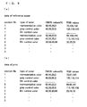
- the first image memory 24 stores the data of the reference paper as partially shown in Fig. 9 (a)
- the second image memory 25 stores the data of the print as partially shown in Fig. 9 (b).
- no Bk control color is selected for the first section.
- no data is present in the corresponding columns.
- CMYK values shown in Figs. 9 (a) and 9 (b) are the PPF data fetched in the image data fetching step (step S11) shown in Fig. 5, which data are common to the reference paper and the print.
- the RGB values are the data obtained by reading the image of the reference paper and the image of the actual print. When a difference exceeding a fixed difference exists between the two groups of RGB values, proper prints are not being produced.
- a density difference is first calculated for each of the representative color, gray control color and Bk control color (step S61).
- the RGB values shown in Fig. 9 are converted to CMYK values. This step is taken because the ink feeding rates are controlled more suitably by the CMYK values which are indexes linked to variations in ink quantity than by the RGB values representing color.
- the density differences of CMYK calculated are multiplied by factors selected according to dot percentages (step S62). That is, a larger density difference occurs in an area of large dot percentage than in an area of small dot percentage.
- the multiplication is carried out in order to secure exact information on the calculated density differences irrespective of dot percentage.
- the dot percentages are calculated by using the CMYK values shown in Fig. 9. However, the dot percentages may by calculated by using the RGB values shown in Fig. 9.
- control data for controlling the ink feeding rates may be obtained by multiplying the density difference of Bk control color by a factor selected according to the K value.
- control data for controlling the feeding rate of each of CMY inks is created by using one or both of a value obtained by multiplying the density difference of the representative color by a factor selected according to the C, M or Y value, and a value obtained by multiplying the density difference of the gray control color by a factor selected according to the C, M or Y value (step S63).
- control data may be created by using only the value obtained by multiplying the density difference of the representative color by a factor selected according to the C, M or Y value, or by using a compromise in an appropriate ratio of the value obtained by multiplying the density difference of the representative color by a factor selected according to the C, M or Y value, and the value obtained by multiplying the density difference of the gray control color by a factor selected according to the C, M or Y value.
- control data for controlling the feeding rates of CMY inks and the control data for controlling the feeding rate of K ink in the above steps are transmitted to the control unit of the printing machine (step S64) to end the entire process.
- a representative color and the like are determined for each of the sections corresponding to the ink keys in each ink well of the printing machine. Instead, a representative color and the like of an entire image may be determined first, and priority may be given to a color close to the above color to determine a representative color and the like for each section.
- a representative color and its positions are determined by using platemaking data or image data based on the platemaking data (PPF data).
- PPF data platemaking data
- a representative color and its positions may be determined based on image data obtained by reading the reference paper.
- platemaking data used for preparing the reference paper or image data based on the platemaking data may be used instead of the image data obtained by reading the reference paper.
- this invention may be implemented also where image data such as PPF data is unavailable as where, for example, a platemaking operation is not digitized.
Landscapes
- Engineering & Computer Science (AREA)
- Multimedia (AREA)
- Signal Processing (AREA)
- Health & Medical Sciences (AREA)
- Biomedical Technology (AREA)
- General Health & Medical Sciences (AREA)
- Quality & Reliability (AREA)
- Facsimile Image Signal Circuits (AREA)
- Inking, Control Or Cleaning Of Printing Machines (AREA)
- Spectrometry And Color Measurement (AREA)
- Image Processing (AREA)
- Image Analysis (AREA)
- Color Image Communication Systems (AREA)
- Accessory Devices And Overall Control Thereof (AREA)
Applications Claiming Priority (2)
| Application Number | Priority Date | Filing Date | Title |
|---|---|---|---|
| JP2002210872 | 2002-07-19 | ||
| JP2002210872A JP4803944B2 (ja) | 2002-07-19 | 2002-07-19 | 印刷物測定方法および印刷物測定装置 |
Publications (3)
| Publication Number | Publication Date |
|---|---|
| EP1385330A2 true EP1385330A2 (de) | 2004-01-28 |
| EP1385330A3 EP1385330A3 (de) | 2007-02-28 |
| EP1385330B1 EP1385330B1 (de) | 2012-12-12 |
Family
ID=29997194
Family Applications (1)
| Application Number | Title | Priority Date | Filing Date |
|---|---|---|---|
| EP03015450A Expired - Lifetime EP1385330B1 (de) | 2002-07-19 | 2003-07-09 | Messverfahren und -gerät für die Druckqualität |
Country Status (3)
| Country | Link |
|---|---|
| US (1) | US7800798B2 (de) |
| EP (1) | EP1385330B1 (de) |
| JP (1) | JP4803944B2 (de) |
Cited By (2)
| Publication number | Priority date | Publication date | Assignee | Title |
|---|---|---|---|---|
| EP1832421A1 (de) * | 2006-03-09 | 2007-09-12 | Dainippon Screen Mfg., Co., Ltd. | Verfahren zur Steuerung der Farbzufuhr und Gerät zur Bestimmung eines repräsentativen Punktes |
| WO2008030522A1 (en) * | 2006-09-06 | 2008-03-13 | Hewlett-Packard Development Company, L.P. | Imaging device and calibration method therefor |
Families Citing this family (13)
| Publication number | Priority date | Publication date | Assignee | Title |
|---|---|---|---|---|
| US7369699B1 (en) * | 2003-08-29 | 2008-05-06 | Apple Inc. | Methods and apparatuses for restoring color and enhancing electronic images |
| EP1525981B1 (de) * | 2003-10-23 | 2006-11-29 | Gretag-Macbeth AG | Farbqualitätsbeurteilung und Farbregelung bei der Farbreproduktion |
| NL1025711C2 (nl) * | 2004-03-12 | 2005-09-13 | Q I Press Controls Holding B V | Werkwijze en systeem voor het controleren van door een drukpers vervaardigd drukwerk. |
| JP2005297346A (ja) * | 2004-04-12 | 2005-10-27 | Dainippon Screen Mfg Co Ltd | 色調制御方法 |
| JP2005342936A (ja) * | 2004-06-01 | 2005-12-15 | Dainippon Screen Mfg Co Ltd | 色調制御方法 |
| CA2891054C (en) * | 2004-12-23 | 2018-02-13 | Dolby Laboratories Licensing Corporation | Wide color gamut displays |
| JP2007194850A (ja) * | 2006-01-18 | 2007-08-02 | Sharp Corp | 画像処理方法、画像処理装置、画像形成装置、及びコンピュータプログラム |
| JP5032911B2 (ja) * | 2007-07-31 | 2012-09-26 | キヤノン株式会社 | 画像処理装置及び画像処理方法 |
| US9355339B2 (en) | 2011-08-26 | 2016-05-31 | Hewlett-Packard Development Company, L.P. | System and method for color reproduction tolerances |
| CN102991122B (zh) * | 2012-11-20 | 2016-06-22 | 北京华夏视科图像技术有限公司 | 墨色控制系统及其控制方法 |
| US11108918B2 (en) | 2017-01-17 | 2021-08-31 | Hewlett-Packard Development Company, L.P. | Assessing print quality using intensity histograms and perimeter lengths |
| DE102017204661B4 (de) * | 2017-03-21 | 2023-12-21 | Heidelberger Druckmaschinen Ag | Dynamische Testformerzeugung mit automatischer Device-Wert-Erkennung |
| CN112721441B (zh) * | 2020-12-23 | 2022-05-06 | 江苏省高淳印刷股份有限公司 | 一种印刷机印刷质量检测装置 |
Citations (1)
| Publication number | Priority date | Publication date | Assignee | Title |
|---|---|---|---|---|
| JP2002205117A (ja) | 2000-12-28 | 2002-07-23 | Nippon Kokan Light Steel Kk | 溝形状断面鋼材の溝幅矯正装置 |
Family Cites Families (22)
| Publication number | Priority date | Publication date | Assignee | Title |
|---|---|---|---|---|
| JPS5952069B2 (ja) * | 1977-12-15 | 1984-12-18 | 凸版印刷株式会社 | 使用インキ量予測装置 |
| US4649502A (en) * | 1983-11-04 | 1987-03-10 | Gretag Aktiengesellschaft | Process and apparatus for evaluating printing quality and for regulating the ink feed controls in an offset printing machine |
| ATE29434T1 (de) | 1983-11-04 | 1987-09-15 | Gretag Ag | Verfahren und vorrichtung zur regelung der farbfuehrung bei einer offset-druckmaschine und mit einer entsprechenden vorrichtung ausgestattete offset-druckmaschine. |
| DE4100170C2 (de) | 1991-01-05 | 1994-10-27 | Roland Man Druckmasch | Farbabstimmpult zur Qualitätskontrolle an Druckbogen |
| US5309228A (en) * | 1991-05-23 | 1994-05-03 | Fuji Photo Film Co., Ltd. | Method of extracting feature image data and method of extracting person's face data |
| US5461457A (en) * | 1992-11-25 | 1995-10-24 | Fuji Photo Film Co., Ltd. | Method of determining amount of exposure |
| FI95888C (fi) | 1993-04-26 | 1996-04-10 | Valtion Teknillinen | Menetelmä painatuksen laadun valvomiseksi |
| DE4321177A1 (de) | 1993-06-25 | 1995-01-05 | Heidelberger Druckmasch Ag | Vorrichtung zur parallelen Bildinspektion und Farbregelung an einem Druckprodukt |
| US5450165A (en) * | 1994-02-23 | 1995-09-12 | Xerox Corporation | System for identifying areas in pre-existing image data as test patches for print quality measurement |
| JP3218910B2 (ja) | 1995-03-28 | 2001-10-15 | 凸版印刷株式会社 | 印刷物評価装置 |
| DE19602103B4 (de) | 1996-01-22 | 2006-05-04 | Heidelberger Druckmaschinen Ag | Verfahren zum Bestimmen von Meßorten für eine Abtastung eines mehrfarbigen Druckbildes zum Steuern oder Regeln einer Farbgebung einer Druckmaschine |
| US5731989A (en) | 1996-04-25 | 1998-03-24 | Advance Vision Technology (A.V.T.) Ltd. | Method and device for determining a measurement for color control in a printing process |
| JP3943167B2 (ja) * | 1996-09-10 | 2007-07-11 | 富士フイルム株式会社 | 色変換方法 |
| US6382101B1 (en) | 1997-03-04 | 2002-05-07 | Heidelberg Harris, Inc. & Heidelberger Druckmaschinen | Remote ink fountain selection method and apparatus |
| JPH10305562A (ja) | 1997-05-02 | 1998-11-17 | Toppan Printing Co Ltd | 印刷物評価装置 |
| JP3905177B2 (ja) * | 1997-05-15 | 2007-04-18 | 富士フイルム株式会社 | 色変換調整方法 |
| DE19802920B4 (de) | 1998-01-27 | 2008-01-31 | Man Roland Druckmaschinen Ag | Verfahren und Vorrichtung zur Farbregelung in Druckmaschinen |
| JP3794825B2 (ja) | 1998-05-21 | 2006-07-12 | 三菱重工業株式会社 | 印刷品質管理方法及び装置 |
| US6775408B1 (en) * | 1999-06-25 | 2004-08-10 | Minolta Co., Ltd. | Image processor |
| JP4228530B2 (ja) * | 2000-02-09 | 2009-02-25 | 富士通株式会社 | 画像処理方法及び画像処理装置 |
| JP2001353852A (ja) | 2000-04-10 | 2001-12-25 | Dainippon Screen Mfg Co Ltd | 印刷装置補助装置 |
| JP4303660B2 (ja) | 2004-08-31 | 2009-07-29 | ニチアス株式会社 | 溶着装置及び溶着方法 |
-
2002
- 2002-07-19 JP JP2002210872A patent/JP4803944B2/ja not_active Expired - Fee Related
-
2003
- 2003-07-09 US US10/615,294 patent/US7800798B2/en not_active Expired - Fee Related
- 2003-07-09 EP EP03015450A patent/EP1385330B1/de not_active Expired - Lifetime
Patent Citations (1)
| Publication number | Priority date | Publication date | Assignee | Title |
|---|---|---|---|---|
| JP2002205117A (ja) | 2000-12-28 | 2002-07-23 | Nippon Kokan Light Steel Kk | 溝形状断面鋼材の溝幅矯正装置 |
Cited By (4)
| Publication number | Priority date | Publication date | Assignee | Title |
|---|---|---|---|---|
| EP1832421A1 (de) * | 2006-03-09 | 2007-09-12 | Dainippon Screen Mfg., Co., Ltd. | Verfahren zur Steuerung der Farbzufuhr und Gerät zur Bestimmung eines repräsentativen Punktes |
| US7643176B2 (en) | 2006-03-09 | 2010-01-05 | Dainippon Screen Mfg. Co., Ltd. | Method and apparatus controlling printed color tone conditionally using a representative point or alternative representative point |
| WO2008030522A1 (en) * | 2006-09-06 | 2008-03-13 | Hewlett-Packard Development Company, L.P. | Imaging device and calibration method therefor |
| US7835043B2 (en) | 2006-09-06 | 2010-11-16 | Hewlett-Packard Development Company, L.P. | Imaging device and calibration method therefor |
Also Published As
| Publication number | Publication date |
|---|---|
| JP4803944B2 (ja) | 2011-10-26 |
| US20040012801A1 (en) | 2004-01-22 |
| EP1385330B1 (de) | 2012-12-12 |
| JP2004050609A (ja) | 2004-02-19 |
| EP1385330A3 (de) | 2007-02-28 |
| US7800798B2 (en) | 2010-09-21 |
Similar Documents
| Publication | Publication Date | Title |
|---|---|---|
| US7800798B2 (en) | Print quality measuring method and print quality measuring apparatus | |
| EP1712361B1 (de) | Vorrichtung zur Farbtrennung einer Druckmaschinen-Farbsteuerung | |
| JP4990466B2 (ja) | 色調整特性曲線を生成する装置 | |
| EP0720351A2 (de) | Verfahren und Gerät zur Erzeugung von Farbprobeabzügen | |
| US20070263263A1 (en) | Method and device for proofing raster print data while maintaining the raster information | |
| US5816151A (en) | Device for alignment of images in a control system for a printing press | |
| US6976425B2 (en) | Ink feeding rate control method and an ink feeding rate control apparatus | |
| EP1641243A2 (de) | Vorrichtung, Programm und Verfahren zur Erstellung eines Profils für ein Bildausgabegerät | |
| US8031363B2 (en) | Methods and apparatus for dynamically soft proofing halftone images | |
| US20020162470A1 (en) | Press profile production method, color management method, printed sheet, and color management system | |
| US7418114B2 (en) | Print tone measuring method | |
| US6968784B2 (en) | Printed tone control apparatus, and method of determining representative points on prints for controlling tone | |
| JP3934576B2 (ja) | 色調制御装置 | |
| US20050264835A1 (en) | Tone control method | |
| JP3862912B2 (ja) | 印刷物検査方法 | |
| JP2004330563A (ja) | 色調制御装置 | |
| CN101155692A (zh) | 利用图像内颜色测量的卷筒纸印刷机的颜色控制 | |
| Södergård et al. | Inspection of colour printing quality | |
| EP1580981A2 (de) | Farbeinstellungsverfahren, Farbbilderzeugungsverfahren und -vorrichtung | |
| JP3748209B2 (ja) | 網点面積率測定方法および網点面積率測定装置 | |
| CA2325263A1 (en) | Optimization apparatus for photographic image data | |
| JP2003291475A (ja) | 画像処理診断方法 | |
| US20080266609A1 (en) | Method and device for proofing raster print data while maintaining the raster information | |
| CA2235015A1 (en) | Real time colour calibration and correction (rt3) |
Legal Events
| Date | Code | Title | Description |
|---|---|---|---|
| PUAI | Public reference made under article 153(3) epc to a published international application that has entered the european phase |
Free format text: ORIGINAL CODE: 0009012 |
|
| AK | Designated contracting states |
Kind code of ref document: A2 Designated state(s): AT BE BG CH CY CZ DE DK EE ES FI FR GB GR HU IE IT LI LU MC NL PT RO SE SI SK TR |
|
| AX | Request for extension of the european patent |
Extension state: AL LT LV MK |
|
| PUAL | Search report despatched |
Free format text: ORIGINAL CODE: 0009013 |
|
| AK | Designated contracting states |
Kind code of ref document: A3 Designated state(s): AT BE BG CH CY CZ DE DK EE ES FI FR GB GR HU IE IT LI LU MC NL PT RO SE SI SK TR |
|
| AX | Request for extension of the european patent |
Extension state: AL LT LV MK |
|
| 17P | Request for examination filed |
Effective date: 20070525 |
|
| AKX | Designation fees paid |
Designated state(s): DE FR GB |
|
| 17Q | First examination report despatched |
Effective date: 20071105 |
|
| GRAP | Despatch of communication of intention to grant a patent |
Free format text: ORIGINAL CODE: EPIDOSNIGR1 |
|
| GRAS | Grant fee paid |
Free format text: ORIGINAL CODE: EPIDOSNIGR3 |
|
| GRAA | (expected) grant |
Free format text: ORIGINAL CODE: 0009210 |
|
| AK | Designated contracting states |
Kind code of ref document: B1 Designated state(s): DE FR GB |
|
| REG | Reference to a national code |
Ref country code: GB Ref legal event code: FG4D |
|
| REG | Reference to a national code |
Ref country code: DE Ref legal event code: R082 Ref document number: 60342813 Country of ref document: DE Representative=s name: KILIAN KILIAN & PARTNER, DE |
|
| REG | Reference to a national code |
Ref country code: DE Ref legal event code: R096 Ref document number: 60342813 Country of ref document: DE Effective date: 20130207 |
|
| PLBE | No opposition filed within time limit |
Free format text: ORIGINAL CODE: 0009261 |
|
| STAA | Information on the status of an ep patent application or granted ep patent |
Free format text: STATUS: NO OPPOSITION FILED WITHIN TIME LIMIT |
|
| 26N | No opposition filed |
Effective date: 20130913 |
|
| REG | Reference to a national code |
Ref country code: DE Ref legal event code: R097 Ref document number: 60342813 Country of ref document: DE Effective date: 20130913 |
|
| REG | Reference to a national code |
Ref country code: FR Ref legal event code: ST Effective date: 20140331 |
|
| PG25 | Lapsed in a contracting state [announced via postgrant information from national office to epo] |
Ref country code: FR Free format text: LAPSE BECAUSE OF NON-PAYMENT OF DUE FEES Effective date: 20130731 |
|
| REG | Reference to a national code |
Ref country code: DE Ref legal event code: R082 Ref document number: 60342813 Country of ref document: DE Representative=s name: KILIAN KILIAN & PARTNER, DE |
|
| REG | Reference to a national code |
Ref country code: DE Ref legal event code: R081 Ref document number: 60342813 Country of ref document: DE Owner name: SCREEN HOLDINGS CO., LTD., JP Free format text: FORMER OWNER: DAINIPPON SCREEN MFG. CO., LTD., KYOTO, JP Effective date: 20150317 Ref country code: DE Ref legal event code: R082 Ref document number: 60342813 Country of ref document: DE Representative=s name: KILIAN KILIAN & PARTNER, DE Effective date: 20130130 Ref country code: DE Ref legal event code: R081 Ref document number: 60342813 Country of ref document: DE Owner name: SCREEN HOLDINGS CO., LTD., JP Free format text: FORMER OWNER: DAINIPPON SCREEN MFG. CO., LTD., KYOTO, JP Effective date: 20121212 Ref country code: DE Ref legal event code: R082 Ref document number: 60342813 Country of ref document: DE Representative=s name: KILIAN KILIAN & PARTNER, DE Effective date: 20150317 Ref country code: DE Ref legal event code: R082 Ref document number: 60342813 Country of ref document: DE Representative=s name: KILIAN KILIAN & PARTNER MBB PATENTANWAELTE, DE Effective date: 20150317 Ref country code: DE Ref legal event code: R082 Ref document number: 60342813 Country of ref document: DE Representative=s name: KILIAN KILIAN & PARTNER MBB PATENTANWAELTE, DE Effective date: 20130130 |
|
| PGFP | Annual fee paid to national office [announced via postgrant information from national office to epo] |
Ref country code: GB Payment date: 20160706 Year of fee payment: 14 Ref country code: DE Payment date: 20160705 Year of fee payment: 14 |
|
| REG | Reference to a national code |
Ref country code: DE Ref legal event code: R119 Ref document number: 60342813 Country of ref document: DE |
|
| GBPC | Gb: european patent ceased through non-payment of renewal fee |
Effective date: 20170709 |
|
| PG25 | Lapsed in a contracting state [announced via postgrant information from national office to epo] |
Ref country code: GB Free format text: LAPSE BECAUSE OF NON-PAYMENT OF DUE FEES Effective date: 20170709 Ref country code: DE Free format text: LAPSE BECAUSE OF NON-PAYMENT OF DUE FEES Effective date: 20180201 |