EP1384891B1 - Sicherheitsmembran für eine Membranpumpe - Google Patents
Sicherheitsmembran für eine Membranpumpe Download PDFInfo
- Publication number
- EP1384891B1 EP1384891B1 EP03014885A EP03014885A EP1384891B1 EP 1384891 B1 EP1384891 B1 EP 1384891B1 EP 03014885 A EP03014885 A EP 03014885A EP 03014885 A EP03014885 A EP 03014885A EP 1384891 B1 EP1384891 B1 EP 1384891B1
- Authority
- EP
- European Patent Office
- Prior art keywords
- diaphragm
- membrane
- layers
- sensor
- safety
- Prior art date
- Legal status (The legal status is an assumption and is not a legal conclusion. Google has not performed a legal analysis and makes no representation as to the accuracy of the status listed.)
- Expired - Lifetime
Links
Images


Classifications
-
- F—MECHANICAL ENGINEERING; LIGHTING; HEATING; WEAPONS; BLASTING
- F04—POSITIVE - DISPLACEMENT MACHINES FOR LIQUIDS; PUMPS FOR LIQUIDS OR ELASTIC FLUIDS
- F04B—POSITIVE-DISPLACEMENT MACHINES FOR LIQUIDS; PUMPS
- F04B43/00—Machines, pumps, or pumping installations having flexible working members
- F04B43/0009—Special features
- F04B43/0081—Special features systems, control, safety measures
- F04B43/009—Special features systems, control, safety measures leakage control; pump systems with two flexible members; between the actuating element and the pumped fluid
-
- F—MECHANICAL ENGINEERING; LIGHTING; HEATING; WEAPONS; BLASTING
- F04—POSITIVE - DISPLACEMENT MACHINES FOR LIQUIDS; PUMPS FOR LIQUIDS OR ELASTIC FLUIDS
- F04B—POSITIVE-DISPLACEMENT MACHINES FOR LIQUIDS; PUMPS
- F04B43/00—Machines, pumps, or pumping installations having flexible working members
- F04B43/0009—Special features
- F04B43/0054—Special features particularities of the flexible members
Definitions
- the present invention relates to a safety diaphragm for diaphragm pumps, which allows to detect a rupture of the diaphragm during operation or at a standstill.
- the Membrane consists of at least three superimposed single membrane layers.
- the gap between the single membrane layers is filled with a buffer liquid.
- the middle membrane layer is provided with slots communicating via a bore with a display device stand.
- a membrane fracture occurs in the space between the single membrane layers in addition to the buffer conveying or hydraulic fluid, which acts on the display device, so that the membrane rupture is signaled. This results in a mixture between conveying or hydraulic fluid and buffer fluid, which is especially in the promotion of aggressive Liquids should be avoided.
- a diaphragm for a diaphragm pump having the features of the preamble of claim 1 is e.g. known from EP-A 0 460 386.
- the object of the present invention was to provide a safety diaphragm for diaphragm pumps to provide a secure detection of breakages in the membrane, without a buffer between different membrane layers requires a simple structure, requires little maintenance, prevents mixing of delivery and hydraulic fluid, detects a membrane rupture before conveying or hydraulic fluid through the membrane can not penetrate to the outside and in any case immediately after the occurrence of a break in the membrane must be replaced, but possibly an emergency operation until the next membrane change allowed.
- the membrane core is preferably centered in Work area of the substantially circular membrane layers arranged and fixed or positive connected with these.
- the working area of the membrane is the section that is at Pressure and suction movement moves up or down.
- the work area extends from the center the substantially circular membrane layers to the outside.
- To the work area of Membrane connects to the outside a clamping area, with which the membrane of the invention is mounted in a pump.
- the clamping region of the membrane according to the invention has in a preferred embodiment, openings passing vertically through the membrane layers for passing bolts for attaching the diaphragm and for accurate positioning on. However, openings or bores are not absolutely necessary.
- the membrane can also be secured by clamping in the pump housing.
- the safety membrane according to the invention consists of at least two, preferably exactly two superimposed membrane layers, these membrane layers on all edge regions where liquid or gas could penetrate between the membrane layers, against a Ingress of liquid and / or gas are tightly interconnected.
- the superimposed arranged membrane layers are thus at least at its peripheral edge and, if available, the through holes in the clamping area and in the center of the membrane core liquid and connected in a gastight manner.
- the other facing surfaces of the superimposed arranged membrane layers are not necessarily firmly connected. Preferably they lie together without a firm connection. Alternatively, the facing each other Areas e.g. by means of vulcanization or adhesive technology sections or selectively fixed to each other be connected. Between the membrane layers according to the invention there is atmospheric or subatmospheric pressure, so that the mutually facing inner surfaces of the membrane layers lie flat on each other in working mode.
- the portion of the sensor area increasing the distance between the opposite Surfaces of the membrane layers pressed apart.
- the membrane layers formed in the portion of the sensor area with a smaller material thickness than in the remaining sections of the membrane.
- the material the membrane layers in the portion of the sensor area a higher elasticity than in the rest Sections of the membrane. Both features can also be realized simultaneously.
- the finding A membrane fracture is carried out according to the invention by means of a sensor, the expansion or increasing the distance between the membrane layers due to the pressure increase between determines the membrane layers.
- a sensor arranged on a deformation of the membrane layers in the portion of the sensor area responds, d. H. the extent of the membrane in the sensor area receives mechanically and forwards in the form of a signal.
- the opposite to the sensor portion of the membrane in the sensor area on a counter surface so that the expansion of the membrane in the sensor area at a fraction of the membrane only in one Direction, namely in the direction of the sensor.
- the safety membrane according to the invention are the superimposed arranged individual membrane layers in one piece by means of plastic molding technology, Vulcanization technology or adhesive technology as a closed and hermetically sealed dense unit formed.
- the safety membrane according to the invention is at least the coming into contact with the medium to be contacted membrane layer coated with a resistant to the medium to be conveyed coating or film.
- a coating with polytetrafluoroethylene (PTFE) has been found.
- At least one of the other facing surfaces of the superposed membrane layers with a coating or film, preferably a PTFE layer, coated. This ensures that do not fuse the superimposed membrane layers together, stick together or otherwise firmly adhere to each other and thereby the spread of the pressure increase in the case disrupted or prevented a diaphragm rupture during operation.
- the working area of the safety membrane according to the invention alternately moved up and down at high frequency, whereas the clamping area in a remains fixed position.
- the transition from the clamping area to the working area where the working area is hinged to the clamping area is therefore particularly high mechanical loads exposed.
- a connecting channel provided, extending from the transition between the work area and clamping area to the sensor area extends.
- this channel is designed in the form of a pressure tube.
- the pressure tube prevents the membrane layers in this section of the clamping area pressure-tight squeezed together and ensures a safe pressure propagation from the transition between clamping area and working area in the sensor area. Further preferred is when between the diaphragm layers near the transition region between clamping area and working area a cavity is formed, in which extends the one end of the pressure tube.
- the cavity near the transition area between chucking and working area is conveniently created by that the material of the membrane layers there has a smaller material thickness than in the other sections the membrane.
- the material thickness in this range should, however, be chosen so that sufficient mechanical stability at the transition between clamping area and working area remains guaranteed.
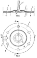
- the safety membrane according to the invention from FIGS. 1 to 5 is composed of two superimposed ones arranged membrane layers 1 and 2 constructed.
- the membrane layers 1 and 2 In plan view, the membrane layers 1 and 2 on a circular circumference. From the center of the membrane layers 1 and 2 to a distance in this embodiment corresponds to about half the radius of the membrane layers extends the work area A. This work area A is followed by the clamping area E, the extends to the peripheral edge of the membrane layers.
- a diaphragm core 5 for the mechanical deflection of the working area of the safety diaphragm or for the suction stroke support of a hydraulically driven safety diaphragm is in the center the working area of the membrane firmly connected to the membrane layers.
- the membrane core 5 is substantially stamp-shaped and has a substantially cylindrical guide rod with fasteners for engagement with a device for actuating the membrane core.
- the diaphragm core 5 has a substantially circular disk-shaped Widening, which is responsible for the attachment of the membrane nucleus to the membrane layers of the material membrane layers 1 and 2 is embraced form fit.
- a support plate 5 ' may additionally be provided a support plate 5 '.
- a circlip 5 "keeps the support disk 5 'on the diaphragm core 5 in position.
- Safety membrane are firmly on all edge areas against ingress of liquid and / or gas interconnected, d. H. at the peripheral edges of the circular membrane layers, at the edges of the mounting holes 3 and at the edges of the through hole for the membrane core 5.
- the material the membrane layers 1 and 2 in the sensor region S formed with a smaller material thickness than in the remaining sections of the membrane. This ensures that the membrane layers in the portion of the sensor area S when increasing the pressure between the membrane layers 1 and 2 deform more easily due to membrane rupture in the portion of the sensor area than in FIG the remaining sections of the membrane. In this deformation, the distance between the Enlarged membrane layers in the sensor area and exerted a pressure on a corresponding sensor, which then indicates the membrane rupture. Due to the smaller material thickness of the membrane layers 1 and 2 in the sensor region S is a cavity in the sensor region between the membrane layers 10 provided. A pressure tube 11 extends from this cavity 10 in the sensor region S.
- the pressure tube 11 ensures a safe spread of increased pressure between the membrane layers, due to a membrane rupture and the ingress of liquid or Gas between the membrane layers 1 and 2 is formed.
- the provision of the cavity 12 in the vicinity the transition 6 ensures that the opening into this cavity 12 end of the pressure tube 11 is not closed by material of the membrane, due to the clamping of the membrane is squeezed in a pump housing in the clamping area.
- a pressure tube It is also possible to use a fabric or a molded part with through-channels.
- the safety membrane according to the invention is the underside of the membrane layer 2, which faces the medium, with a PTFE film coated.
- a PTFE film coated As a result, the material of the membrane layer is protected from attack protected aggressive media.
- the provision of this protective PTFE film 16 allows the material of the membrane layers according to the requirements of the mechanical stress Select pumps without compromising on chemical resistance to have to go.
- the PTFE film any other chemical and / or mechanical The material resistant to the medium to be used. Examples of suitable Protective films are known to those skilled in the art.
- the safety membrane according to the invention according to FIGS. 1 to 5 furthermore has a PTFE film 15 between the membrane layers 1 and 2.
- This PTFE film 15 prevents the material the membrane layers z. B. due to high heat generation during operation glued together and thereby a spread of pressure between the membrane layers at a membrane breakage is prevented.
- the membrane layer 1 in the sensor region S a further PTFE disc 13, which prevents sticking of the membrane layers in the sensor area.
- a sensor contact surface is on the outside of the membrane layer 2 facing the sensor 14 is provided, on which a sensor with the sensor region S of the safety diaphragm is brought into contact.
- a sensor with the sensor region S of the safety diaphragm is brought into contact.
- the material bulges lower diaphragm layer 2 together with the sensor contact surface 14 to the outside and actuates the Sensor.
- the opposite portion of the membrane layer 1 in the sensor region S at the at illustrated embodiment, no sensor is provided, preferably located on a fixed counter surface at. This ensures that the entire extent of the membrane layers in the sensor region S completely in the direction of the arranged on the lower membrane layer 2 sensor extends.
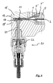
- FIG. 6 shows a broken view of the membrane according to the invention from FIGS to 5 in a pump housing 19 with a sensor 20 for detecting an expansion of Membrane layers in sensor area S in the event of a diaphragm rupture.
- the safety membrane according to the invention still be used for a certain period of time in an "emergency operation" as the respective unbroken membrane layer a passage of fluid or hydraulic fluid prevented by the entire membrane.
- the safety membrane according to the invention ensures that a membrane rupture is detected before liquid passes through the membrane and either the fluid or an optionally provided hydraulic fluid can contaminate.
- the safety membrane according to the invention can with regard to their Shape and external dimensions are made as conventional membranes, so that It can be used without much extra effort in existing pump housing. It is only on the pump housing an additional hole for the insertion of a sensor provided.
- the safety membrane according to the invention also requires a considerably lower Maintenance as a known safety diaphragm to indicate a diaphragm rupture.
Landscapes
- Engineering & Computer Science (AREA)
- Mechanical Engineering (AREA)
- General Engineering & Computer Science (AREA)
- Reciprocating Pumps (AREA)
- External Artificial Organs (AREA)
- Medicines Containing Material From Animals Or Micro-Organisms (AREA)
- Separation Using Semi-Permeable Membranes (AREA)
Description
- die Membran vom äußeren Umfang aus in Richtung der Mitte einen in Umfangsrichtung verlaufenden Einspannbereich (E) für die Befestigung der Membran in einer Pumpe und einen sich daran anschließenden Arbeitsbereich (A) aufweist,
- die Membranlagen derart miteinander verbunden sind, daß sie gegen ein Eindringen von Flüssigkeit und/oder Gas zwischen die Membranlagen dicht sind,
- in einem Abschnitt des Einspannbereiches (E) der Membran ein Sensorbereich (S) vorgesehen ist,
- zwischen den Membranlagen atmosphärischer oder unteratmosphärischer Druck herrscht,
- die Membranlagen in dem Abschnitt des Sensorbereiches (S) so ausgebildet sind, daß sie sich bei Erhöhung des Drucks zwischen den Membranlagen in dem Abschnitt des Sensorbereiches unter Vergrößerung des Abstandes zwischen den Membranlagen leichter deformieren als in den übrigen Abschnitten der Membran.
- Figur 1
- zeigt einen Querschnitt einer erfindungsgemäßen Sicherheitsmembran entlang der Linie C-C aus Figur 4.
- Figur 2
- ist eine vergrößerte Darstellung des Sicherheitsbereichs der Membran aus Figur 1.
- Figur 3
- zeigt einen Querschnitt der erfindungsgemäßen Sicherheitsmembran entlang der Linie D-D aus Figur 4.
- Figur 4
- zeigt eine schematische Darstellung der erfindungsgemäßen Sicherheitsmembran aus Figuren 1 bis 3 von unten.
- Figur 5
- zeigt eine Explosionsdarstellung der erfindungsgemäßen Sicherheitsmembran der Figuren 1 bis 4.
- Figur 6
- zeigt eine schematische Darstellung eines Sensors für die erfindungsgemäße Sicherheitsmembran im Querschnitt.
Claims (7)
- Sicherheitsmembran für eine Membranpumpe mit wenigstens zwei übereinanderliegend angeordneten Membranlagen (1, 2) mit im wesentlichen kreisförmigem Umfang, wobeidie Membran vom äußeren Umfang aus in Richtung der Mitte einen in Umfangsrichtung verlaufenden Einspannbereich (E) für die Befestigung der Membran in einer Pumpe und einen sich daran anschließenden Arbeitsbereich (A) aufweist,die Membranlagen (1, 2) derart miteinander verbunden sind, dass sie gegen ein Eindringen von Flüssigkeit und/oder Gas zwischen die Membranlagen dicht sind, dadurch gekennzeichnet dassin einem Abschnitt des Einspannbereiches (E) der Membran ein Sensorbereich (S) vorgesehen ist,zwischen den Membranlagen (1, 2) atmosphärischer oder unteratmosphärischer Druck herrscht,die Membranlagen (1, 2) in dem Abschnitt des Sensorbereiches (S) so ausgebildet sind, dass sie sich bei Erhöhung des Drucks zwischen den Membranlagen (1, 2) in dem Abschnitt des Sensorbereiches (S) unter Vergrößerung des Abstandes zwischen den Membranlagen leichter deformieren als in den übrigen Abschnitten der Membran.
- Sicherheitsmembran nach Anspruch 1, dadurch gekennzeichnet, dass an dem Sensorbereich (S) der Membran ein Sensor angeordnet ist, welcher auf eine Deformation der Membranlagen (1, 2) in dem Abschnitt des Sensorbereiches (S) anspricht.
- Sicherheitsmembran nach einem der Ansprüche 1 oder 2, dadurch gekennzeichnet, dass die Membranlagen (1, 2) in dem Abschnitt des Sensorbereiches (S) eine geringere Materialdicke aufweisen als in den übrigen Abschnitten der Membran.
- Sicherheitsmembran nach einem der Ansprüche 1 bis 3, dadurch gekennzeichnet, dass die Membranlagen (1, 2) in dem Abschnitt des Sensorbereiches (S) eine höhere Elastizität aufweisen als in den übrigen Abschnitten der Membran.
- Sicherheitsmembran nach einem der Ansprüche 1 bis 4, dadurch gekennzeichnet, dass die einander zugewandten Innenflächen der Membranlagen (1, 2) in dem Abschnitt des Sensorbereiches (S) unter Ausbildung eines Hohlraumes einen Abstand zueinander aufweisen.
- Sicherheitsmembran nach einem der Ansprüche 1 bis 5, dadurch gekennzeichnet, dass die Membran im Zentrum des Arbeitsbereichs einen Membrankern (5) aufweist, mit dem die Membranlagen (1, 2) vorzugsweise formschlüssig dicht verbunden sind.
- Sicherheitsmembran nach Anspruch 6, dadurch gekennzeichnet, dass am Membrankern weiterhin eine Stützscheibe (5') vorgesehen ist.
Applications Claiming Priority (2)
| Application Number | Priority Date | Filing Date | Title |
|---|---|---|---|
| DE10233561A DE10233561B4 (de) | 2002-07-24 | 2002-07-24 | Sicherheitsmembran für eine Membranpumpe |
| DE10233561 | 2002-07-24 |
Publications (2)
| Publication Number | Publication Date |
|---|---|
| EP1384891A1 EP1384891A1 (de) | 2004-01-28 |
| EP1384891B1 true EP1384891B1 (de) | 2005-03-09 |
Family
ID=29796544
Family Applications (1)
| Application Number | Title | Priority Date | Filing Date |
|---|---|---|---|
| EP03014885A Expired - Lifetime EP1384891B1 (de) | 2002-07-24 | 2003-07-01 | Sicherheitsmembran für eine Membranpumpe |
Country Status (7)
| Country | Link |
|---|---|
| US (1) | US6907816B2 (de) |
| EP (1) | EP1384891B1 (de) |
| AT (1) | ATE290652T1 (de) |
| DE (2) | DE10233561B4 (de) |
| DK (1) | DK1384891T3 (de) |
| ES (1) | ES2236649T3 (de) |
| PT (1) | PT1384891E (de) |
Cited By (3)
| Publication number | Priority date | Publication date | Assignee | Title |
|---|---|---|---|---|
| DE102008053050A1 (de) * | 2008-10-24 | 2010-04-29 | Prominent Dosiertechnik Gmbh | Membranbruchanzeige |
| DE102009045773A1 (de) | 2009-10-16 | 2011-04-21 | Prominent Dosiertechnik Gmbh | Druckhalteventil |
| DE102023132946A1 (de) * | 2023-11-27 | 2025-05-28 | Prominent Gmbh | Membranbruchmeldeeinrichtung |
Families Citing this family (12)
| Publication number | Priority date | Publication date | Assignee | Title |
|---|---|---|---|---|
| DE102004002079A1 (de) * | 2004-01-15 | 2005-08-11 | Knf Flodos Ag | Membranpumpe |
| US7295131B2 (en) * | 2005-01-07 | 2007-11-13 | Rosemount Inc. | Diagnostic system for detecting rupture or thinning of diaphragms |
| EP2061971A2 (de) * | 2006-09-16 | 2009-05-27 | THOMAS MAGNETE GmbH | Membranpumpe |
| DE102007015152A1 (de) | 2007-03-22 | 2008-09-25 | Carl Zeiss Industrielle Messtechnik Gmbh | Maschine zum Vermessen oder Bearbeiten von Werkstücken, insbesondere Koordinatenmessgerät |
| DE102007059239A1 (de) * | 2007-12-07 | 2009-06-10 | Thomas Magnete Gmbh | Membran, und Hubkolben-Membranpumpe |
| EP2085614B1 (de) * | 2008-01-31 | 2011-03-23 | J. Wagner AG | Fördervorrichtung, insbesondere Doppel-Membran-Kolbenpumpe |
| DE102009023012A1 (de) * | 2009-05-28 | 2010-12-16 | G.S. Anderson Gmbh | Membranventil-Membran |
| DE102016216006A1 (de) * | 2016-08-25 | 2018-03-01 | Siemens Aktiengesellschaft | Doppelmembran für eine Staubpumpe |
| CN110939558A (zh) * | 2018-09-25 | 2020-03-31 | 苏州芙路德润滑科技有限公司 | 一种计量泵泵膜 |
| DE102019109283A1 (de) | 2019-04-09 | 2020-10-15 | Prominent Gmbh | Membranbruchüberwachung |
| DE102020120204A1 (de) | 2020-07-30 | 2022-02-03 | Peter Pelz | Hub-Vorrichtung und Membran-Eintakt-Motor |
| DE102023132443B3 (de) | 2023-11-21 | 2025-03-27 | Prominent Gmbh | Dosierpumpe mit Membranbefestigung am Antrieb durch Einhaken |
Family Cites Families (10)
| Publication number | Priority date | Publication date | Assignee | Title |
|---|---|---|---|---|
| US2662478A (en) * | 1950-01-31 | 1953-12-15 | Surre Francois Eugene | Diaphragm pump and compressor |
| US3131638A (en) * | 1962-07-05 | 1964-05-05 | Lapp Insulator Company Inc | Leak detecting device |
| FR1552305A (de) * | 1967-12-15 | 1969-01-03 | ||
| US3661060A (en) * | 1970-08-05 | 1972-05-09 | Duriron Co | Diaphragms for high pressure compressors and pumps |
| FR2624922B1 (fr) * | 1987-12-17 | 1990-04-27 | Milton Roy Dosapro | Dispositif de detection de rupture d'une membrane de pompe a membrane |
| DE3931516C2 (de) * | 1989-09-21 | 1993-10-14 | Ott Kg Lewa | Membranpumpe mit mechanisch angetriebener Membran |
| FR2657923B1 (fr) * | 1990-02-08 | 1994-06-10 | Milton Roy Dosapro | Perfectionnement a un dispositif detecteur de rupture de membrane dans une pompe a membrane double. |
| DE4018464A1 (de) * | 1990-06-08 | 1991-12-12 | Ott Kg Lewa | Membran fuer eine hydraulisch angetriebene membranpumpe |
| DE4027027C2 (de) * | 1990-08-27 | 1994-04-07 | Prominent Dosiertechnik Gmbh | Verfahren zur Erkennung einer Bruchstelle in einer Membran und Membranfördereinheit |
| DE59207956D1 (de) * | 1991-05-03 | 1997-03-06 | Regipur Polyurethan Anlagen Te | Mehrlagen-membran mit leckage-ableitung für membranpumpen |
-
2002
- 2002-07-24 DE DE10233561A patent/DE10233561B4/de not_active Expired - Fee Related
-
2003
- 2003-07-01 DE DE50300342T patent/DE50300342D1/de not_active Expired - Lifetime
- 2003-07-01 PT PT03014885T patent/PT1384891E/pt unknown
- 2003-07-01 DK DK03014885T patent/DK1384891T3/da active
- 2003-07-01 EP EP03014885A patent/EP1384891B1/de not_active Expired - Lifetime
- 2003-07-01 AT AT03014885T patent/ATE290652T1/de active
- 2003-07-01 ES ES03014885T patent/ES2236649T3/es not_active Expired - Lifetime
- 2003-07-21 US US10/624,745 patent/US6907816B2/en not_active Expired - Lifetime
Cited By (4)
| Publication number | Priority date | Publication date | Assignee | Title |
|---|---|---|---|---|
| DE102008053050A1 (de) * | 2008-10-24 | 2010-04-29 | Prominent Dosiertechnik Gmbh | Membranbruchanzeige |
| DE102009045773A1 (de) | 2009-10-16 | 2011-04-21 | Prominent Dosiertechnik Gmbh | Druckhalteventil |
| WO2011045318A1 (de) | 2009-10-16 | 2011-04-21 | Prominent Dosiertechnik Gmbh | Druckhalteventil |
| DE102023132946A1 (de) * | 2023-11-27 | 2025-05-28 | Prominent Gmbh | Membranbruchmeldeeinrichtung |
Also Published As
| Publication number | Publication date |
|---|---|
| DE10233561B4 (de) | 2008-02-21 |
| DE10233561A1 (de) | 2004-02-12 |
| DE50300342D1 (de) | 2005-04-14 |
| EP1384891A1 (de) | 2004-01-28 |
| US20040083883A1 (en) | 2004-05-06 |
| PT1384891E (pt) | 2005-06-30 |
| ATE290652T1 (de) | 2005-03-15 |
| DK1384891T3 (da) | 2005-06-06 |
| US6907816B2 (en) | 2005-06-21 |
| ES2236649T3 (es) | 2005-07-16 |
Similar Documents
| Publication | Publication Date | Title |
|---|---|---|
| EP1384891A1 (de) | Sicherheitsmembran für eine Membranpumpe | |
| DE3931516C2 (de) | Membranpumpe mit mechanisch angetriebener Membran | |
| EP0460386B1 (de) | Membran für eine hydraulisch angetriebene Membranpumpe | |
| EP0685721B1 (de) | Vorrichtung zum Messen des Drucks eines Mediums | |
| DE1800018C3 (de) | Hydraulische Membranpumpe | |
| DE2324876C2 (de) | Filterplatte für eine Plattenfilterpresse | |
| DE2826033C2 (de) | Infusionspumpe | |
| EP0742398A1 (de) | Ventil mit einer Membranabdichtung | |
| DE3783972T2 (de) | Luftdruckpumpeinrichtung. | |
| EP0125456B1 (de) | Membranplatte für Kammerfilterpressen | |
| EP1503839B1 (de) | Plattenpaket für eine filterpresse | |
| EP0582628B1 (de) | Mehrlagen-membran mit leckage-ableitung für membranpumpen | |
| EP0684061B1 (de) | Filterplatte für eine Plattenfilterpresse | |
| DE2145571C3 (de) | Schlauchquetschpumpe | |
| DE2146016A1 (de) | Vorrichtung zum sichern und ggfs. verbessern einer membranpumpe | |
| DE4027027C2 (de) | Verfahren zur Erkennung einer Bruchstelle in einer Membran und Membranfördereinheit | |
| DE3146222C2 (de) | Membranpumpe mit einer Membranbruchanzeigevorrichtung | |
| DE10324818A1 (de) | Abdichtung eines Sensorelementes | |
| DE3729726A1 (de) | Membranmaschineneinheit | |
| DE4143371C2 (de) | Membran für eine Membranpumpe | |
| DE29507638U1 (de) | Ventil | |
| DE1916595C3 (de) | Druckschalter für eine elektrische Warnvorrichtung, insbesondere zur Überwachung des Druckes in einem mit Unterdruck betriebenen Bremskraftverstärker einer Kraftfahrzeugbremsanlage | |
| WO2004101104A1 (de) | Leckageanzeige für ein filterelement einer filterpresse | |
| DE2728720C2 (de) | ||
| DE3929372A1 (de) | Koksofentuer |
Legal Events
| Date | Code | Title | Description |
|---|---|---|---|
| PUAI | Public reference made under article 153(3) epc to a published international application that has entered the european phase |
Free format text: ORIGINAL CODE: 0009012 |
|
| AK | Designated contracting states |
Kind code of ref document: A1 Designated state(s): AT BE BG CH CY CZ DE DK EE ES FI FR GB GR HU IE IT LI LU MC NL PT RO SE SI SK TR |
|
| AX | Request for extension of the european patent |
Extension state: AL LT LV MK |
|
| 17P | Request for examination filed |
Effective date: 20040713 |
|
| GRAP | Despatch of communication of intention to grant a patent |
Free format text: ORIGINAL CODE: EPIDOSNIGR1 |
|
| AKX | Designation fees paid |
Designated state(s): AT BE BG CH CY CZ DE DK EE ES FI FR GB GR HU IE IT LI LU MC NL PT RO SE SI SK TR |
|
| GRAS | Grant fee paid |
Free format text: ORIGINAL CODE: EPIDOSNIGR3 |
|
| GRAA | (expected) grant |
Free format text: ORIGINAL CODE: 0009210 |
|
| AK | Designated contracting states |
Kind code of ref document: B1 Designated state(s): AT BE BG CH CY CZ DE DK EE ES FI FR GB GR HU IE IT LI LU MC NL PT RO SE SI SK TR |
|
| PG25 | Lapsed in a contracting state [announced via postgrant information from national office to epo] |
Ref country code: SK Free format text: LAPSE BECAUSE OF FAILURE TO SUBMIT A TRANSLATION OF THE DESCRIPTION OR TO PAY THE FEE WITHIN THE PRESCRIBED TIME-LIMIT Effective date: 20050309 Ref country code: IE Free format text: LAPSE BECAUSE OF FAILURE TO SUBMIT A TRANSLATION OF THE DESCRIPTION OR TO PAY THE FEE WITHIN THE PRESCRIBED TIME-LIMIT Effective date: 20050309 Ref country code: RO Free format text: LAPSE BECAUSE OF FAILURE TO SUBMIT A TRANSLATION OF THE DESCRIPTION OR TO PAY THE FEE WITHIN THE PRESCRIBED TIME-LIMIT Effective date: 20050309 Ref country code: TR Free format text: LAPSE BECAUSE OF FAILURE TO SUBMIT A TRANSLATION OF THE DESCRIPTION OR TO PAY THE FEE WITHIN THE PRESCRIBED TIME-LIMIT Effective date: 20050309 Ref country code: EE Free format text: LAPSE BECAUSE OF FAILURE TO SUBMIT A TRANSLATION OF THE DESCRIPTION OR TO PAY THE FEE WITHIN THE PRESCRIBED TIME-LIMIT Effective date: 20050309 Ref country code: SI Free format text: LAPSE BECAUSE OF FAILURE TO SUBMIT A TRANSLATION OF THE DESCRIPTION OR TO PAY THE FEE WITHIN THE PRESCRIBED TIME-LIMIT Effective date: 20050309 |
|
| REG | Reference to a national code |
Ref country code: GB Ref legal event code: FG4D Free format text: NOT ENGLISH |
|
| REG | Reference to a national code |
Ref country code: CH Ref legal event code: EP |
|
| REG | Reference to a national code |
Ref country code: IE Ref legal event code: FG4D Free format text: GERMAN |
|
| REF | Corresponds to: |
Ref document number: 50300342 Country of ref document: DE Date of ref document: 20050414 Kind code of ref document: P |
|
| REG | Reference to a national code |
Ref country code: CH Ref legal event code: NV Representative=s name: ISLER & PEDRAZZINI AG |
|
| REG | Reference to a national code |
Ref country code: SE Ref legal event code: TRGR |
|
| REG | Reference to a national code |
Ref country code: GR Ref legal event code: EP Ref document number: 20050401424 Country of ref document: GR |
|
| REG | Reference to a national code |
Ref country code: DK Ref legal event code: T3 |
|
| PG25 | Lapsed in a contracting state [announced via postgrant information from national office to epo] |
Ref country code: BG Free format text: LAPSE BECAUSE OF FAILURE TO SUBMIT A TRANSLATION OF THE DESCRIPTION OR TO PAY THE FEE WITHIN THE PRESCRIBED TIME-LIMIT Effective date: 20050609 |
|
| PG25 | Lapsed in a contracting state [announced via postgrant information from national office to epo] |
Ref country code: HU Free format text: LAPSE BECAUSE OF FAILURE TO SUBMIT A TRANSLATION OF THE DESCRIPTION OR TO PAY THE FEE WITHIN THE PRESCRIBED TIME-LIMIT Effective date: 20050610 |
|
| GBT | Gb: translation of ep patent filed (gb section 77(6)(a)/1977) |
Effective date: 20050525 |
|
| REG | Reference to a national code |
Ref country code: PT Ref legal event code: SC4A Free format text: AVAILABILITY OF NATIONAL TRANSLATION Effective date: 20050512 |
|
| PG25 | Lapsed in a contracting state [announced via postgrant information from national office to epo] |
Ref country code: CY Free format text: LAPSE BECAUSE OF FAILURE TO SUBMIT A TRANSLATION OF THE DESCRIPTION OR TO PAY THE FEE WITHIN THE PRESCRIBED TIME-LIMIT Effective date: 20050701 Ref country code: LU Free format text: LAPSE BECAUSE OF NON-PAYMENT OF DUE FEES Effective date: 20050701 |
|
| REG | Reference to a national code |
Ref country code: ES Ref legal event code: FG2A Ref document number: 2236649 Country of ref document: ES Kind code of ref document: T3 |
|
| PG25 | Lapsed in a contracting state [announced via postgrant information from national office to epo] |
Ref country code: MC Free format text: LAPSE BECAUSE OF NON-PAYMENT OF DUE FEES Effective date: 20050731 |
|
| REG | Reference to a national code |
Ref country code: IE Ref legal event code: FD4D |
|
| PLBE | No opposition filed within time limit |
Free format text: ORIGINAL CODE: 0009261 |
|
| STAA | Information on the status of an ep patent application or granted ep patent |
Free format text: STATUS: NO OPPOSITION FILED WITHIN TIME LIMIT |
|
| ET | Fr: translation filed | ||
| 26N | No opposition filed |
Effective date: 20051212 |
|
| REG | Reference to a national code |
Ref country code: CH Ref legal event code: PCAR Free format text: ISLER & PEDRAZZINI AG;POSTFACH 1772;8027 ZUERICH (CH) |
|
| REG | Reference to a national code |
Ref country code: DE Ref legal event code: R082 Ref document number: 50300342 Country of ref document: DE Representative=s name: WSL PATENTANWAELTE PARTNERSCHAFT MBB, DE |
|
| REG | Reference to a national code |
Ref country code: DE Ref legal event code: R082 Ref document number: 50300342 Country of ref document: DE Representative=s name: WSL PATENTANWAELTE PARTNERSCHAFT MBB, DE Effective date: 20140613 Ref country code: DE Ref legal event code: R081 Ref document number: 50300342 Country of ref document: DE Owner name: PROMINENT GMBH, DE Free format text: FORMER OWNER: PROMINENT DOSIERTECHNIK GMBH, 69123 HEIDELBERG, DE Effective date: 20140613 |
|
| REG | Reference to a national code |
Ref country code: CH Ref legal event code: PFA Owner name: PROMINENT GMBH, DE Free format text: FORMER OWNER: PROMINENT DOSIERTECHNIK GMBH, DE |
|
| REG | Reference to a national code |
Ref country code: ES Ref legal event code: PC2A Owner name: PROMINENT GMBH Effective date: 20141219 |
|
| REG | Reference to a national code |
Ref country code: FR Ref legal event code: CD Owner name: PROMINENT GMBH Effective date: 20141201 |
|
| REG | Reference to a national code |
Ref country code: NL Ref legal event code: TD Effective date: 20150122 |
|
| REG | Reference to a national code |
Ref country code: FR Ref legal event code: PLFP Year of fee payment: 14 |
|
| REG | Reference to a national code |
Ref country code: FR Ref legal event code: PLFP Year of fee payment: 15 |
|
| REG | Reference to a national code |
Ref country code: FR Ref legal event code: PLFP Year of fee payment: 16 |
|
| PGFP | Annual fee paid to national office [announced via postgrant information from national office to epo] |
Ref country code: NL Payment date: 20190719 Year of fee payment: 17 |
|
| PGFP | Annual fee paid to national office [announced via postgrant information from national office to epo] |
Ref country code: SE Payment date: 20190719 Year of fee payment: 17 Ref country code: ES Payment date: 20190822 Year of fee payment: 17 Ref country code: FI Payment date: 20190722 Year of fee payment: 17 Ref country code: CZ Payment date: 20190628 Year of fee payment: 17 Ref country code: PT Payment date: 20190701 Year of fee payment: 17 Ref country code: FR Payment date: 20190719 Year of fee payment: 17 |
|
| PGFP | Annual fee paid to national office [announced via postgrant information from national office to epo] |
Ref country code: GR Payment date: 20190716 Year of fee payment: 17 Ref country code: BE Payment date: 20190718 Year of fee payment: 17 |
|
| PGFP | Annual fee paid to national office [announced via postgrant information from national office to epo] |
Ref country code: AT Payment date: 20190722 Year of fee payment: 17 |
|
| PGFP | Annual fee paid to national office [announced via postgrant information from national office to epo] |
Ref country code: CH Payment date: 20190719 Year of fee payment: 17 |
|
| PG25 | Lapsed in a contracting state [announced via postgrant information from national office to epo] |
Ref country code: CZ Free format text: LAPSE BECAUSE OF NON-PAYMENT OF DUE FEES Effective date: 20200701 |
|
| REG | Reference to a national code |
Ref country code: FI Ref legal event code: MAE |
|
| REG | Reference to a national code |
Ref country code: CH Ref legal event code: PL |
|
| REG | Reference to a national code |
Ref country code: SE Ref legal event code: EUG |
|
| REG | Reference to a national code |
Ref country code: NL Ref legal event code: MM Effective date: 20200801 |
|
| REG | Reference to a national code |
Ref country code: AT Ref legal event code: MM01 Ref document number: 290652 Country of ref document: AT Kind code of ref document: T Effective date: 20200701 |
|
| REG | Reference to a national code |
Ref country code: BE Ref legal event code: MM Effective date: 20200731 |
|
| PG25 | Lapsed in a contracting state [announced via postgrant information from national office to epo] |
Ref country code: FR Free format text: LAPSE BECAUSE OF NON-PAYMENT OF DUE FEES Effective date: 20200731 Ref country code: FI Free format text: LAPSE BECAUSE OF NON-PAYMENT OF DUE FEES Effective date: 20200701 Ref country code: PT Free format text: LAPSE BECAUSE OF NON-PAYMENT OF DUE FEES Effective date: 20210203 Ref country code: NL Free format text: LAPSE BECAUSE OF NON-PAYMENT OF DUE FEES Effective date: 20200801 Ref country code: LI Free format text: LAPSE BECAUSE OF NON-PAYMENT OF DUE FEES Effective date: 20200731 Ref country code: GR Free format text: LAPSE BECAUSE OF NON-PAYMENT OF DUE FEES Effective date: 20210210 Ref country code: CH Free format text: LAPSE BECAUSE OF NON-PAYMENT OF DUE FEES Effective date: 20200731 |
|
| PG25 | Lapsed in a contracting state [announced via postgrant information from national office to epo] |
Ref country code: SE Free format text: LAPSE BECAUSE OF NON-PAYMENT OF DUE FEES Effective date: 20200702 Ref country code: AT Free format text: LAPSE BECAUSE OF NON-PAYMENT OF DUE FEES Effective date: 20200701 Ref country code: BE Free format text: LAPSE BECAUSE OF NON-PAYMENT OF DUE FEES Effective date: 20200731 |
|
| REG | Reference to a national code |
Ref country code: ES Ref legal event code: FD2A Effective date: 20211126 |
|
| PG25 | Lapsed in a contracting state [announced via postgrant information from national office to epo] |
Ref country code: ES Free format text: LAPSE BECAUSE OF NON-PAYMENT OF DUE FEES Effective date: 20200702 |
|
| PGFP | Annual fee paid to national office [announced via postgrant information from national office to epo] |
Ref country code: IT Payment date: 20220726 Year of fee payment: 20 Ref country code: GB Payment date: 20220722 Year of fee payment: 20 Ref country code: DK Payment date: 20220725 Year of fee payment: 20 Ref country code: DE Payment date: 20220622 Year of fee payment: 20 |
|
| REG | Reference to a national code |
Ref country code: DE Ref legal event code: R071 Ref document number: 50300342 Country of ref document: DE |
|
| REG | Reference to a national code |
Ref country code: DK Ref legal event code: EUP Expiry date: 20230701 |
|
| REG | Reference to a national code |
Ref country code: GB Ref legal event code: PE20 Expiry date: 20230630 |
|
| PG25 | Lapsed in a contracting state [announced via postgrant information from national office to epo] |
Ref country code: GB Free format text: LAPSE BECAUSE OF EXPIRATION OF PROTECTION Effective date: 20230630 |