EP1384516A2 - Turbinenmotor eines Rotationszerstäubers - Google Patents
Turbinenmotor eines Rotationszerstäubers Download PDFInfo
- Publication number
- EP1384516A2 EP1384516A2 EP03016336A EP03016336A EP1384516A2 EP 1384516 A2 EP1384516 A2 EP 1384516A2 EP 03016336 A EP03016336 A EP 03016336A EP 03016336 A EP03016336 A EP 03016336A EP 1384516 A2 EP1384516 A2 EP 1384516A2
- Authority
- EP
- European Patent Office
- Prior art keywords
- drive
- turbine
- turbine engine
- engine according
- bearing unit
- Prior art date
- Legal status (The legal status is an assumption and is not a legal conclusion. Google has not performed a legal analysis and makes no representation as to the accuracy of the status listed.)
- Granted
Links
Images
Classifications
-
- B—PERFORMING OPERATIONS; TRANSPORTING
- B05—SPRAYING OR ATOMISING IN GENERAL; APPLYING FLUENT MATERIALS TO SURFACES, IN GENERAL
- B05B—SPRAYING APPARATUS; ATOMISING APPARATUS; NOZZLES
- B05B3/00—Spraying or sprinkling apparatus with moving outlet elements or moving deflecting elements
- B05B3/02—Spraying or sprinkling apparatus with moving outlet elements or moving deflecting elements with rotating elements
- B05B3/10—Spraying or sprinkling apparatus with moving outlet elements or moving deflecting elements with rotating elements discharging over substantially the whole periphery of the rotating member
- B05B3/1035—Driving means; Parts thereof, e.g. turbine, shaft, bearings
-
- B—PERFORMING OPERATIONS; TRANSPORTING
- B05—SPRAYING OR ATOMISING IN GENERAL; APPLYING FLUENT MATERIALS TO SURFACES, IN GENERAL
- B05B—SPRAYING APPARATUS; ATOMISING APPARATUS; NOZZLES
- B05B5/00—Electrostatic spraying apparatus; Spraying apparatus with means for charging the spray electrically; Apparatus for spraying liquids or other fluent materials by other electric means
- B05B5/025—Discharge apparatus, e.g. electrostatic spray guns
- B05B5/04—Discharge apparatus, e.g. electrostatic spray guns characterised by having rotary outlet or deflecting elements, i.e. spraying being also effected by centrifugal forces
- B05B5/0415—Driving means; Parts thereof, e.g. turbine, shaft, bearings
-
- F—MECHANICAL ENGINEERING; LIGHTING; HEATING; WEAPONS; BLASTING
- F01—MACHINES OR ENGINES IN GENERAL; ENGINE PLANTS IN GENERAL; STEAM ENGINES
- F01D—NON-POSITIVE DISPLACEMENT MACHINES OR ENGINES, e.g. STEAM TURBINES
- F01D1/00—Non-positive-displacement machines or engines, e.g. steam turbines
- F01D1/18—Non-positive-displacement machines or engines, e.g. steam turbines without stationary working-fluid guiding means
- F01D1/22—Non-positive-displacement machines or engines, e.g. steam turbines without stationary working-fluid guiding means traversed by the working-fluid substantially radially
-
- F—MECHANICAL ENGINEERING; LIGHTING; HEATING; WEAPONS; BLASTING
- F01—MACHINES OR ENGINES IN GENERAL; ENGINE PLANTS IN GENERAL; STEAM ENGINES
- F01D—NON-POSITIVE DISPLACEMENT MACHINES OR ENGINES, e.g. STEAM TURBINES
- F01D15/00—Adaptations of machines or engines for special use; Combinations of engines with devices driven thereby
- F01D15/06—Adaptations for driving, or combinations with, hand-held tools or the like control thereof
- F01D15/065—Adaptations for driving, or combinations with, hand-held tools or the like control thereof with pressure-velocity transformation exclusively in rotor
-
- F—MECHANICAL ENGINEERING; LIGHTING; HEATING; WEAPONS; BLASTING
- F02—COMBUSTION ENGINES; HOT-GAS OR COMBUSTION-PRODUCT ENGINE PLANTS
- F02C—GAS-TURBINE PLANTS; AIR INTAKES FOR JET-PROPULSION PLANTS; CONTROLLING FUEL SUPPLY IN AIR-BREATHING JET-PROPULSION PLANTS
- F02C1/00—Gas-turbine plants characterised by the use of hot gases or unheated pressurised gases, as the working fluid
-
- Y—GENERAL TAGGING OF NEW TECHNOLOGICAL DEVELOPMENTS; GENERAL TAGGING OF CROSS-SECTIONAL TECHNOLOGIES SPANNING OVER SEVERAL SECTIONS OF THE IPC; TECHNICAL SUBJECTS COVERED BY FORMER USPC CROSS-REFERENCE ART COLLECTIONS [XRACs] AND DIGESTS
- Y02—TECHNOLOGIES OR APPLICATIONS FOR MITIGATION OR ADAPTATION AGAINST CLIMATE CHANGE
- Y02T—CLIMATE CHANGE MITIGATION TECHNOLOGIES RELATED TO TRANSPORTATION
- Y02T50/00—Aeronautics or air transport
- Y02T50/60—Efficient propulsion technologies, e.g. for aircraft
Definitions
- the invention relates to a drive for the bell cup a rotary atomizer usable turbine engine according to the The preamble of claim 1. Furthermore, the invention relates to a Rotary atomizer with such a turbine engine.
- Such atomizer (DE 43 06 80, EP 0 796 663 B1) are known to serve operated with compressed air radial turbines whose Rotated bell cup bearing hollow shaft in an air bearing.
- the radial turbine can either be tangential or radial be flowed through.
- that is Turbine wheel from one in a largely closed cylindrical Interior of the bearing unit of the drive shaft rotating Slice on its one end face near the perimeter Turbine blades are formed.
- the drive air flows through the turbine blades radially in a channel on his one side of the turbine wheel and in the known case its opposite side by a fixed part the storage unit is limited.
- the drive air enters this Drive channel through one or more supply channels, which open in a nozzle whose cross-section, e.g. quadrangular Opening in the known case, the smallest cross-section of the respective Represents drive air supply.
- the storage unit consists of an air gap through which a part of the Drive air for the drive is lost.
- Another disadvantage is a turbulent boundary layer located at the considered known Radial turbine between the flowing drive air and the fixed housing part forms and high friction losses caused. As a result, the performance of the known Radial turbine limited.
- the invention is based on the object, a turbine engine for a rotary atomizer specify the higher drive power as possible with comparable known radial turbines.
- the invention makes the turbine fluidically essential improved.
- the drive channel not as previously limited only one-sided, but also on the other side closed by a co-rotating element is, the drive air, the loss of the closed channel and flow through it with little friction.
- An expedient realization possibility consists in the drive channel by a on the Turbine wheel and / or attached to the drive shaft and with to limit it rotating disk, which is at least one radial form inside outlet opening for the drive air or may contain.
- the cross-sectional area the inlet opening through which the drive air from a supply channel of the storage unit in the drive channel the turbine flows be greater than the cross sectional area of the Supply channel in its place smallest cross-section.
- the inlet can be called a Laval or supersonic nozzle be formed, whose cross section is initially narrows and then to generate velocities of the gas flow extended, at least theoretically in the supersonic range can lie.
- the turbine can be optimized in terms of flow which, above all, higher speeds than before be enabled.
- a rotary atomizer is with the higher speed a higher discharge rate of the coating material reached at the driven by the turbine bell cup.
- the mass of the total known as Modular unit interchangeable motor unit (without bell plate) less than 0.8 kg, which was previously only essential less powerful turbine engines of the type considered was possible.
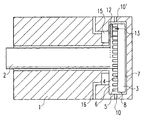
- the drawing shows in schematic simplified representation of a section through the storage unit a rotary atomizer along the axis of the drive shaft.
- the bearing unit forming the turbine engine described herein has a fixed housing 1, in which the drive shaft 2 in an air bearing formed between the housing and the shaft rotates.
- the disc-shaped Turbine wheel 3 arranged on a nearby of the disk circumference lying ring area of its facing the shaft axial end face 4 of the radially to be flowed through Wreath of turbine blades 5 are formed.
- the turbine wheel 3 rotates in a dimensioned according to the turbine wheel cylindrical Interior 6 of the housing 1 with close to the back plane end face 7 and the cylindrical peripheral surface. 8 of the turbine wheel adjacent walls.
- Radial outside the circumference of the turbine wheel 3 and in the axial Direction aligned with the turbine blades 5 opens into the Interior 6 an inlet 10 for the drive air of the turbine, from a running through the housing 1 supply channel comes.
- another air inlet may be provided.
- the housing 1 contains separate inlets for drive air and brake air (EP Application No. 02006826.8).
- the drive shaft can be designed as a hollow shaft, in the other End of the (not shown) bell cup of Rotationszerstäubers is screwed.
- turbine blades in the described closed Drive channel not only on one, but on both Provide sides of the turbine wheel. It is also possible to arrange more than one turbine on a common shaft.
- the cross-sectional area of the orifice at the air inlet 10, So at the exit point of the drive air, is preferably larger as the smallest cross section of the preceding channels of the Storage unit in which the drive air in a conventional manner through at least one bore in a ring segment-shaped Supply channel and passes from this into one or more nozzles.
- the air inlet 10 is e.g. as a Laval nozzle formed, the cross-section is initially narrowed and then expanded to the mouth opening to extended Nozzle part to produce supersonic speeds.
- Supersonic nozzles can not only be used for the radial turbine described here. but also for different types of turbine engines Performance increase be beneficial.
- Turbine wheel of two axially spaced disc elements For example, these can be performed on the perimeter be connected to axial webs, between which passage openings are released for the air flow, so the between The drive channel formed the disc elements also on the circumference the turbine wheel is partially closed. Further, it can the outlet for the drive air instead of radially inside the one Disc element at any other place and possibly also located radially outside the turbine wheel.
- the invention is moreover neither to the described tangential or radial direction of flow still on two spaced discs still on a particular shape of the blade elements limited.
- the vane elements between a closed cylindrical Area on the circumference of the turbine wheel and one of them radially spaced inner, also closed cylindrical Arrange surface so that a double-sided radially limited drive channel is formed, wherein the blade elements flows axially are and air outlets on the axially opposite End of the annular drive channel can be located.
Landscapes
- Engineering & Computer Science (AREA)
- Mechanical Engineering (AREA)
- General Engineering & Computer Science (AREA)
- Chemical & Material Sciences (AREA)
- Combustion & Propulsion (AREA)
- Electrostatic Spraying Apparatus (AREA)
- Nozzles (AREA)
- Special Spraying Apparatus (AREA)
Abstract
Description
Claims (10)
- Turbinenmotor, der als Antrieb für den Glockenteller eines Rotationszerstäubers verwendbar ist,
mit einer Lagereinheit für die Antriebswelle (2) des Motors, mit einem an der Antriebswelle (2) angeordneten Turbinenrad (3), das in einem Innenraum (6) eines Gehäuses (1) der Lagereinheit rotiert und an einer Trägerfläche (4) Schaüfelelemente (5) äufweist,
mit einem aus dem Gehäuse (1) in dessen Innenraum (6) führenden Einlass (10) für ein Antriebsgas wie insbesondere Druckluft, das durch einen die Schäufelelemente (5) enthaltenden Antriebskanal (13) strömt,
und mit einem Auslass für das aus dem Innenraum (6) abfließende Antriebsgas,
dadurch gekennzeichnet, dass der Antriebskahal (13) auf seiner der Trägerfläche (4) des Turbinenrades (3) gegenüberliegenden Seite von einem an die Schäufelelemente (5) angrenzenden Element (12) begrenzt ist. - Turbinenmotor nach Anspruch 1 dadurch gekennzeichnet, dass das Turbinenrad durch zwei einander axial gegenüberliegende, fest miteinander verbundene Scheibenelemente (3, 12) gebildet ist, die zwischen sich den die Turbinenschaufeln (5) enthaltenden Antriebskanal (13) begrenzen.
- Turbinenmotor nach Anspruch 1 oder 2, dadurch gekennzeichnet, dass das Begrenzungselement eine an dem Turbinenrad (3) und/oder an der Antriebswelle (2) befestigte und mit ihnen rotierende Scheibe (12) ist.
- Turbinenmotor nach Anspruch 2 oder 3, dadurch gekennzeichnet, dass die Scheibe (12) an die Turbinenschaufeln (5) angeklebt ist.
- Turbinenmotor nach Anspruch 2 oder 3, dadurch gekennzeichnet, dass die Scheibe (12) an die Turbinenschaufeln (5) angeschweißt ist.
- Turbinenmotor nach einem der vorangehenden Ansprüche, dadurch gekennzeichnet, dass das Begrenzungselement (12) mindestens eine Auslassöffnung für das Antriebsgas bildet oder enthält.
- Turbinenmotor nach einem der vorangehenden Ansprüche, dadurch gekennzeichnet,. dass mindestens eine Auslassöffnung für das Antriebsgas in dem Gehäuse (1) der Lagereinheit an einer von der Antriebswelle (2) radial entfernten Stelle vorgesehen ist.
- Turbinenmotor mit einer Lagereinheit für die Antriebswelle (2) des Motors, mit einem an der Antriebswelle (2) angeordneten Turbinenrad (3), das in einem Innenraum (6) eines Gehäuses (1) der Lägereinheit rotiert und Schaufelelemente (5) aufweist, mit einem aus dem Gehäuse (1) in den Innenraum (6) führenden Einlass (10) für ein Antriebsgas wie insbesondere Druckluft, und mit einem Auslass für das aus dem Innenraum (6) abfließende Antriebsgas, insbesondere nach einem der Ansprüche 1 bis 7,
dadurch gekennzeichnet, dass die Querschnittsfläche der Mündungsöffnung (10), durch die das Antriebsgas aus einem innerhalb der Lagereinheit befindlichen Zuleitungskanal in den die Schaufelelemente (5) enthaltenden Antriebskanal (13) strömt, größer ist als die Querschnittsfläche des Zuleitungskanals an seiner Stelle kleinsten Querschnitts. - Turbinenmotor nach Anspruch 8, dadurch gekennzeichnet, dass der Einlass (10) als Laval-Düse ausgebildet ist, deren Querschnitt sich nach einer Verengung bis zu der in den Antriebskanal (13) führenden Öffnung erweitert.
- Rotationszerstäuber einer Anlage für die Serienbeschichtung von Werkstücken mit einem Turbinenmotor nach einem der vorangehenden Ansprüche.
Priority Applications (1)
| Application Number | Priority Date | Filing Date | Title |
|---|---|---|---|
| EP11008307.8A EP2407247B1 (de) | 2002-07-22 | 2003-07-18 | Turbinenmotor eines Rotationszerstäubers |
Applications Claiming Priority (2)
| Application Number | Priority Date | Filing Date | Title |
|---|---|---|---|
| DE10233199A DE10233199A1 (de) | 2002-07-22 | 2002-07-22 | Turbinenmotor eines Rotationszerstäubers |
| DE10233199 | 2002-07-22 |
Related Child Applications (1)
| Application Number | Title | Priority Date | Filing Date |
|---|---|---|---|
| EP11008307.8A Division EP2407247B1 (de) | 2002-07-22 | 2003-07-18 | Turbinenmotor eines Rotationszerstäubers |
Publications (3)
| Publication Number | Publication Date |
|---|---|
| EP1384516A2 true EP1384516A2 (de) | 2004-01-28 |
| EP1384516A3 EP1384516A3 (de) | 2008-03-12 |
| EP1384516B1 EP1384516B1 (de) | 2011-11-16 |
Family
ID=29796498
Family Applications (2)
| Application Number | Title | Priority Date | Filing Date |
|---|---|---|---|
| EP11008307.8A Expired - Lifetime EP2407247B1 (de) | 2002-07-22 | 2003-07-18 | Turbinenmotor eines Rotationszerstäubers |
| EP03016336A Expired - Lifetime EP1384516B1 (de) | 2002-07-22 | 2003-07-18 | Turbinenmotor eines Rotationszerstäubers |
Family Applications Before (1)
| Application Number | Title | Priority Date | Filing Date |
|---|---|---|---|
| EP11008307.8A Expired - Lifetime EP2407247B1 (de) | 2002-07-22 | 2003-07-18 | Turbinenmotor eines Rotationszerstäubers |
Country Status (6)
| Country | Link |
|---|---|
| US (1) | US7322793B2 (de) |
| EP (2) | EP2407247B1 (de) |
| AT (1) | ATE533563T1 (de) |
| DE (1) | DE10233199A1 (de) |
| ES (2) | ES2603059T3 (de) |
| PT (1) | PT1384516E (de) |
Cited By (7)
| Publication number | Priority date | Publication date | Assignee | Title |
|---|---|---|---|---|
| DE102008057160A1 (de) * | 2008-11-13 | 2010-05-20 | Mtu Aero Engines Gmbh | Verfahren zum Austausch eines inneren Scheibenelements einer integral beschaufelten Scheibe |
| US7967552B2 (en) | 2004-09-03 | 2011-06-28 | Neil Edward Brett | Drive spindles |
| DE102012010610A1 (de) * | 2012-05-30 | 2013-12-05 | Eisenmann Ag | Verfahren zum Betreiben eines Rotationszerstäubers, Düsenkopf und Rotationszerstäuber mit einem solchen |
| CN107120769A (zh) * | 2016-02-24 | 2017-09-01 | 王建峰 | 一种雾化盘及具有该雾化盘的雾化电机 |
| KR20170106365A (ko) * | 2015-01-20 | 2017-09-20 | 듀르 시스템스 아게 | 회전식 분무기 터빈 |
| CN113578553A (zh) * | 2021-08-25 | 2021-11-02 | 重庆忠泽科技有限公司 | 一种用于钢塑复合管内壁喷涂的弥散喷头 |
| WO2023174697A1 (de) | 2022-03-15 | 2023-09-21 | Dürr Systems Ag | Turbinenantrieb für einen rotationszerstäuber und zugehöriges betriebsverfahren |
Families Citing this family (10)
| Publication number | Priority date | Publication date | Assignee | Title |
|---|---|---|---|---|
| DE10303617A1 (de) * | 2003-01-30 | 2004-10-07 | GAT Gesellschaft für Antriebstechnik mbH | Turbinenrad zum Antrieb schnell rotierender Werkzeuge |
| DE10239517A1 (de) * | 2002-08-28 | 2004-03-11 | Dürr Systems GmbH | Beschichtungseinrichtung mit einem Rotationszerstäuber und Verfahren zum Steuern ihres Betriebes |
| DE102006003799B4 (de) * | 2006-01-25 | 2010-05-06 | Daimler Ag | Brennstoffzellensystem mit Brennstoffzelle, Wasserstoffspeicher und Anodenkreislauf und dessen Verwendung |
| EP2506981B1 (de) * | 2009-12-04 | 2018-02-14 | The Regents Of The University Of Michigan | Koaxiallasergestützte kaltsprühdüse |
| USD873874S1 (en) | 2012-09-28 | 2020-01-28 | Dürr Systems Ag | Axial turbine housing for a rotary atomizer for a painting robot |
| DE102010013551B4 (de) | 2010-03-31 | 2016-12-08 | Dürr Systems Ag | Turbinenrotor und Antriebsturbine für einen Rotationszerstäuber und Rotationszerstäuber |
| JP5387765B2 (ja) * | 2010-11-29 | 2014-01-15 | 日本精工株式会社 | エアモータ及び静電塗装装置 |
| EP2774686B1 (de) * | 2011-11-04 | 2019-05-08 | NSK Ltd. | Spindelvorrichtung und elektrostatische beschichtungsvorrichtung |
| DE102014015702A1 (de) * | 2014-10-22 | 2016-04-28 | Eisenmann Se | Hochrotationszerstäuber |
| JP6762808B2 (ja) * | 2016-08-30 | 2020-09-30 | Ntn株式会社 | エアタービン駆動スピンドル |
Citations (4)
| Publication number | Priority date | Publication date | Assignee | Title |
|---|---|---|---|---|
| US3968935A (en) | 1973-05-21 | 1976-07-13 | Sohre John S | Contoured supersonic nozzle |
| GB1474134A (en) | 1973-07-17 | 1977-05-18 | Rhone Poulenc Textile | Turbine |
| EP0567436A1 (de) | 1992-04-23 | 1993-10-27 | E. Fischer Ag Sfi-Schleifspindelfabrik | Farbspritzdüse |
| EP0984136A1 (de) | 1998-09-01 | 2000-03-08 | SCHMID & WEZEL GmbH & Co. | Doppelseitige Zentrifugal- Zentripedalturbine |
Family Cites Families (42)
| Publication number | Priority date | Publication date | Assignee | Title |
|---|---|---|---|---|
| NL4075C (de) * | 1913-10-31 | |||
| DE430680C (de) | 1924-02-07 | 1926-06-23 | J G Farbenindustrie Ag | Verfahren zur Erzeugung von Mehrfarbeneffekten bzw. von Mischtoenen auf der pflanzlichen Faser |
| DE560836C (de) * | 1929-12-05 | 1932-10-07 | Wilhelm Seyerle Dr Ing | Axial beaufschlagte Turbine |
| US2411798A (en) * | 1944-07-05 | 1946-11-26 | Arthur H Matthews | Gas turbine |
| FR969291A (fr) * | 1948-07-09 | 1950-12-18 | Matemine Sa | Tuyère de détente réglable pour l'écoulement des fluides compressibles |
| GB885367A (en) * | 1959-03-14 | 1961-12-28 | Svenska Rotor Maskiner Ab | Improvements in or relating to the production of blade wheels |
| DE1426847A1 (de) * | 1965-06-08 | 1969-10-16 | Reinhardt Berta | Druckluft-Gleichdruckturbine |
| US3804335A (en) * | 1973-05-21 | 1974-04-16 | J Sohre | Vaneless supersonic nozzle |
| US4022423A (en) * | 1975-07-30 | 1977-05-10 | Kieley & Mueller, Inc. | Control valve |
| US4355949A (en) * | 1980-02-04 | 1982-10-26 | Caterpillar Tractor Co. | Control system and nozzle for impulse turbines |
| US4376135A (en) * | 1981-03-20 | 1983-03-08 | Binks Manufacturing Company | Apparatus for atomization in electrostatic coating and method |
| AU526982B2 (en) * | 1981-04-16 | 1983-02-10 | Ransburg Corp. | Coating material atomizing and dispensing system |
| DE3214314A1 (de) * | 1982-04-19 | 1983-10-20 | J. Wagner AG, 9450 Altstätten | Elektrostatische spruehvorrichtung |
| GB8320827D0 (en) * | 1983-08-02 | 1983-09-01 | Sale Tilney Technology Ltd | Coating workpieces |
| US4589597A (en) * | 1983-10-03 | 1986-05-20 | Graco Inc. | Rotary atomizer spray painting device |
| CH668008A5 (de) * | 1985-04-30 | 1988-11-30 | H U Ramseier Fa | Elektrostatische pulverbeschichtungsanlage. |
| FR2584314B1 (fr) * | 1985-07-05 | 1988-04-29 | Sames Sa | Tete atomisante rotative, notamment pour peinture electrostatique |
| US4684064A (en) * | 1985-08-19 | 1987-08-04 | Graco Inc. | Centrifugal atomizer |
| DE3609240C2 (de) * | 1986-03-19 | 1996-08-01 | Behr Industrieanlagen | Vorrichtung zum elektrostatischen Beschichten von Gegenständen |
| US4919333A (en) * | 1986-06-26 | 1990-04-24 | The Devilbiss Company | Rotary paint atomizing device |
| EP0283918B1 (de) * | 1987-03-23 | 1991-07-10 | Behr Industrieanlagen GmbH & Co. | Vorrichtung zum elektrostatischen Beschichten von Werkstücken |
| DE3720201C1 (de) * | 1987-06-16 | 1988-09-08 | Ransburg Gmbh | Spruehbeschichtungseinrichtung mit einer ringfoermigen Elektrodenanordnung fuer elektrisch leitfaehige Beschichtungsfluessigkeiten |
| JPH0195269U (de) * | 1987-12-18 | 1989-06-23 | ||
| US4927081A (en) * | 1988-09-23 | 1990-05-22 | Graco Inc. | Rotary atomizer |
| DE3920981A1 (de) * | 1989-06-27 | 1991-01-10 | Ist Molchtechnik Gmbh | Rohrleitungsmolch |
| US5078321A (en) * | 1990-06-22 | 1992-01-07 | Nordson Corporation | Rotary atomizer cup |
| RU2008435C1 (ru) * | 1991-02-11 | 1994-02-28 | Нижегородский государственный технический университет | Радиальная турбина |
| DE4121455C2 (de) * | 1991-06-28 | 1994-10-27 | Wagner Int | Einrichtung zum Speisen von Pulverbeschichtungsgeräten mit einem Pulver-Luft-Gemisch |
| US5397063A (en) * | 1992-04-01 | 1995-03-14 | Asahi Sunac Corporation | Rotary atomizer coater |
| US5288215A (en) * | 1992-11-19 | 1994-02-22 | Chancellor Dennis H | Integral motor centrifugal pump |
| US5633306A (en) * | 1992-12-03 | 1997-05-27 | Ransburg Corporation | Nonincendive rotary atomizer |
| DE4306800C2 (de) * | 1993-03-04 | 1998-07-02 | Duerr Gmbh & Co | Beschichtungsvorrichtung mit einem Rotationszerstäuber |
| US5300006A (en) * | 1993-07-02 | 1994-04-05 | Okuma Machine Tools Inc. | Automatic tool changer |
| US5683032A (en) * | 1995-06-29 | 1997-11-04 | Ford Global Technologies, Inc. | Air measuring apparatus and method for paint rotary bell atomizers |
| FR2738303B1 (fr) | 1995-08-30 | 1997-11-28 | Europ Propulsion | Turbine en materiau composite thermostructural, en particulier a petit diametre, et procede pour sa fabrication |
| JP3322100B2 (ja) * | 1995-11-09 | 2002-09-09 | 日産自動車株式会社 | 回転霧化静電塗装装置 |
| DE19611369A1 (de) | 1996-03-22 | 1997-09-25 | Duerr Gmbh & Co | Rotationszerstäuber zum elektrostatisch unterstützten Beschichten von Gegenständen mit Farben bzw. Lacken |
| DE19728155A1 (de) * | 1997-07-03 | 1999-01-07 | Lactec Gmbh | Verfahren und Vorrichtung zum Lackieren |
| DE19805938A1 (de) * | 1998-02-13 | 1999-08-19 | Lactec Gmbh | Verfahren und Vorrichtung zum Beschichten von Teilen |
| DE19959473A1 (de) * | 1999-12-10 | 2001-06-13 | Frederic Dietrich | Vorrichtung und Verfahren zum pneumatischen Fördern pulverförmiger Stoffe sowie Verwendung der Vorrichtung |
| DE10059041C2 (de) * | 2000-11-28 | 2002-11-14 | Lactec Ges Fuer Moderne Lackte | Verfahren und Vorrichtung zum Fördern von elektrisch leitfähigen Lacken zwischen unterschiedlichen Spannungspotenzialen |
| US20080236007A1 (en) | 2005-01-07 | 2008-10-02 | Kammy Au | Electronic Display Panels for Automobiles |
-
2002
- 2002-07-22 DE DE10233199A patent/DE10233199A1/de not_active Withdrawn
-
2003
- 2003-07-18 PT PT03016336T patent/PT1384516E/pt unknown
- 2003-07-18 EP EP11008307.8A patent/EP2407247B1/de not_active Expired - Lifetime
- 2003-07-18 ES ES11008307.8T patent/ES2603059T3/es not_active Expired - Lifetime
- 2003-07-18 EP EP03016336A patent/EP1384516B1/de not_active Expired - Lifetime
- 2003-07-18 AT AT03016336T patent/ATE533563T1/de active
- 2003-07-18 ES ES03016336T patent/ES2376196T3/es not_active Expired - Lifetime
- 2003-07-22 US US10/624,173 patent/US7322793B2/en not_active Expired - Lifetime
Patent Citations (4)
| Publication number | Priority date | Publication date | Assignee | Title |
|---|---|---|---|---|
| US3968935A (en) | 1973-05-21 | 1976-07-13 | Sohre John S | Contoured supersonic nozzle |
| GB1474134A (en) | 1973-07-17 | 1977-05-18 | Rhone Poulenc Textile | Turbine |
| EP0567436A1 (de) | 1992-04-23 | 1993-10-27 | E. Fischer Ag Sfi-Schleifspindelfabrik | Farbspritzdüse |
| EP0984136A1 (de) | 1998-09-01 | 2000-03-08 | SCHMID & WEZEL GmbH & Co. | Doppelseitige Zentrifugal- Zentripedalturbine |
Cited By (9)
| Publication number | Priority date | Publication date | Assignee | Title |
|---|---|---|---|---|
| US7967552B2 (en) | 2004-09-03 | 2011-06-28 | Neil Edward Brett | Drive spindles |
| DE102008057160A1 (de) * | 2008-11-13 | 2010-05-20 | Mtu Aero Engines Gmbh | Verfahren zum Austausch eines inneren Scheibenelements einer integral beschaufelten Scheibe |
| DE102012010610A1 (de) * | 2012-05-30 | 2013-12-05 | Eisenmann Ag | Verfahren zum Betreiben eines Rotationszerstäubers, Düsenkopf und Rotationszerstäuber mit einem solchen |
| US9707578B2 (en) | 2012-05-30 | 2017-07-18 | Eisenmann Se | Rotary atomizer nozzle head, and rotary atomizer with such a nozzle head |
| KR20170106365A (ko) * | 2015-01-20 | 2017-09-20 | 듀르 시스템스 아게 | 회전식 분무기 터빈 |
| CN107120769A (zh) * | 2016-02-24 | 2017-09-01 | 王建峰 | 一种雾化盘及具有该雾化盘的雾化电机 |
| CN113578553A (zh) * | 2021-08-25 | 2021-11-02 | 重庆忠泽科技有限公司 | 一种用于钢塑复合管内壁喷涂的弥散喷头 |
| WO2023174697A1 (de) | 2022-03-15 | 2023-09-21 | Dürr Systems Ag | Turbinenantrieb für einen rotationszerstäuber und zugehöriges betriebsverfahren |
| DE102022105999A1 (de) | 2022-03-15 | 2023-09-21 | Dürr Systems Ag | Turbinenantrieb für einen Rotationszerstäuber und zugehöriges Betriebsverfahren |
Also Published As
| Publication number | Publication date |
|---|---|
| EP2407247A1 (de) | 2012-01-18 |
| ATE533563T1 (de) | 2011-12-15 |
| ES2603059T3 (es) | 2017-02-23 |
| EP2407247B1 (de) | 2016-08-31 |
| EP1384516B1 (de) | 2011-11-16 |
| US20040164190A1 (en) | 2004-08-26 |
| EP1384516A3 (de) | 2008-03-12 |
| DE10233199A1 (de) | 2004-02-05 |
| US7322793B2 (en) | 2008-01-29 |
| ES2376196T3 (es) | 2012-03-09 |
| PT1384516E (pt) | 2012-02-07 |
Similar Documents
| Publication | Publication Date | Title |
|---|---|---|
| EP1384516B1 (de) | Turbinenmotor eines Rotationszerstäubers | |
| DE60130234T2 (de) | Luft/öl separator | |
| DE19615237C2 (de) | Abgasturbolader für eine Brennkraftmaschine | |
| DE69906019T2 (de) | Zentrifuge mit konischen Trennwänden | |
| DE2653504C2 (de) | ||
| DE3042017C2 (de) | ||
| EP3456945A1 (de) | Getriebe mit einem ölverteilungssystem | |
| DE102012104598A1 (de) | Abscheider und Verfahren zum Abscheiden von Flüssigkeitströpfchen aus einem Aerosol | |
| DE2031612A1 (de) | Vielstufiger Axialkompressor mit einem Luftableitsystem als Zwischen stufe | |
| EP2009288A2 (de) | Turbolader mit integriertem Separator | |
| DE10236017B3 (de) | Rotationszerstäuberturbine und Rotationszerstäuber | |
| EP2054587B1 (de) | Turbinengehäuse | |
| EP0786058B1 (de) | Automatgetriebe, insbesondere für kraftfahrzeuge | |
| DE102007003088B3 (de) | Strömungsmaschine in einem angetriebenen Rotor | |
| DE102012100438A1 (de) | Abscheider für Flüssigkeitströpfchen aus einem Aerosol | |
| EP0154205A1 (de) | Explosions-Turbinen-Motor | |
| DE102018124654B4 (de) | Einrichtung zum Abscheiden von Partikeln aus einem Gasstrom, Partikelabscheider und Kurbelgehäuseentlüftungssystem | |
| DE202015106402U1 (de) | Fluidgetriebener Antrieb und Aktuator | |
| DE10256805A1 (de) | Elektromotor, insbesondere für Elektrohandwerkzeugmaschinen | |
| WO1994003733A1 (de) | Mehrstufige ejektorpumpe | |
| EP2874558B1 (de) | Zahnärztliches präparationsinstrument | |
| DE3887678T2 (de) | Druckluftmotor mit rückdrucktreibscheibe. | |
| EP0781896B1 (de) | Turbinenrad für Impulsturbinen | |
| DE3203498A1 (de) | Wirbelkammerfilter zum ausscheiden von feststoffen aus einem gasstrom | |
| DE102017119070B4 (de) | Strahltriebwerk |
Legal Events
| Date | Code | Title | Description |
|---|---|---|---|
| PUAI | Public reference made under article 153(3) epc to a published international application that has entered the european phase |
Free format text: ORIGINAL CODE: 0009012 |
|
| AK | Designated contracting states |
Kind code of ref document: A2 Designated state(s): AT BE BG CH CY CZ DE DK EE ES FI FR GB GR HU IE IT LI LU MC NL PT RO SE SI SK TR |
|
| AX | Request for extension of the european patent |
Extension state: AL LT LV MK |
|
| RIN1 | Information on inventor provided before grant (corrected) |
Inventor name: BAUMANN, MICHAEL Inventor name: HERRE, FRANK Inventor name: KRUMMA, HARRY Inventor name: LIND, BJOERNLIND GAS BEARING TECHNOLOGY AB Inventor name: GIULIANO, STEFANO Inventor name: NOLTE, HANS-JUERGEN, DR. |
|
| RIC1 | Information provided on ipc code assigned before grant |
Ipc: F01D 15/06 20060101ALN20070328BHEP Ipc: B05B 5/04 20060101AFI20031108BHEP Ipc: B05B 3/10 20060101ALI20070328BHEP |
|
| PUAL | Search report despatched |
Free format text: ORIGINAL CODE: 0009013 |
|
| AK | Designated contracting states |
Kind code of ref document: A3 Designated state(s): AT BE BG CH CY CZ DE DK EE ES FI FR GB GR HU IE IT LI LU MC NL PT RO SE SI SK TR |
|
| AX | Request for extension of the european patent |
Extension state: AL LT LV MK |
|
| RIC1 | Information provided on ipc code assigned before grant |
Ipc: F01D 9/02 20060101ALI20080206BHEP Ipc: B05B 3/10 20060101ALI20080206BHEP Ipc: B05B 5/04 20060101AFI20031108BHEP Ipc: F01D 15/06 20060101ALN20070328BHEP |
|
| 17P | Request for examination filed |
Effective date: 20080806 |
|
| AKX | Designation fees paid |
Designated state(s): AT BE BG CH CY CZ DE DK EE ES FI FR GB GR HU IE IT LI LU MC NL PT RO SE SI SK TR |
|
| RAP1 | Party data changed (applicant data changed or rights of an application transferred) |
Owner name: DUERR SYSTEMS GMBH |
|
| 17Q | First examination report despatched |
Effective date: 20100421 |
|
| GRAP | Despatch of communication of intention to grant a patent |
Free format text: ORIGINAL CODE: EPIDOSNIGR1 |
|
| RIN1 | Information on inventor provided before grant (corrected) |
Inventor name: NOLTE, HANS-JUERGEN Inventor name: LIND, BJOERNLIND GAS BEARING TECHNOLOGY AB Inventor name: KRUMMA, HARRY Inventor name: HERRE, FRANK Inventor name: GIULIANO, STEFANO Inventor name: BAUMANN, MICHAEL |
|
| GRAS | Grant fee paid |
Free format text: ORIGINAL CODE: EPIDOSNIGR3 |
|
| GRAA | (expected) grant |
Free format text: ORIGINAL CODE: 0009210 |
|
| AK | Designated contracting states |
Kind code of ref document: B1 Designated state(s): AT BE BG CH CY CZ DE DK EE ES FI FR GB GR HU IE IT LI LU MC NL PT RO SE SI SK TR |
|
| REG | Reference to a national code |
Ref country code: GB Ref legal event code: FG4D Free format text: NOT ENGLISH |
|
| REG | Reference to a national code |
Ref country code: CH Ref legal event code: EP |
|
| REG | Reference to a national code |
Ref country code: IE Ref legal event code: FG4D Free format text: LANGUAGE OF EP DOCUMENT: GERMAN |
|
| REG | Reference to a national code |
Ref country code: DE Ref legal event code: R081 Ref document number: 50314071 Country of ref document: DE Owner name: DUERR SYSTEMS AG, DE Free format text: FORMER OWNER: DUERR SYSTEMS GMBH, 70435 STUTTGART, DE |
|
| REG | Reference to a national code |
Ref country code: PT Ref legal event code: SC4A Free format text: AVAILABILITY OF NATIONAL TRANSLATION Effective date: 20120127 |
|
| REG | Reference to a national code |
Ref country code: DE Ref legal event code: R096 Ref document number: 50314071 Country of ref document: DE Effective date: 20120223 |
|
| REG | Reference to a national code |
Ref country code: NL Ref legal event code: VDEP Effective date: 20111116 |
|
| REG | Reference to a national code |
Ref country code: SK Ref legal event code: T3 Ref document number: E 10704 Country of ref document: SK |
|
| REG | Reference to a national code |
Ref country code: ES Ref legal event code: FG2A Ref document number: 2376196 Country of ref document: ES Kind code of ref document: T3 Effective date: 20120309 |
|
| PG25 | Lapsed in a contracting state [announced via postgrant information from national office to epo] |
Ref country code: SE Free format text: LAPSE BECAUSE OF FAILURE TO SUBMIT A TRANSLATION OF THE DESCRIPTION OR TO PAY THE FEE WITHIN THE PRESCRIBED TIME-LIMIT Effective date: 20111116 Ref country code: NL Free format text: LAPSE BECAUSE OF FAILURE TO SUBMIT A TRANSLATION OF THE DESCRIPTION OR TO PAY THE FEE WITHIN THE PRESCRIBED TIME-LIMIT Effective date: 20111116 Ref country code: SI Free format text: LAPSE BECAUSE OF FAILURE TO SUBMIT A TRANSLATION OF THE DESCRIPTION OR TO PAY THE FEE WITHIN THE PRESCRIBED TIME-LIMIT Effective date: 20111116 Ref country code: GR Free format text: LAPSE BECAUSE OF FAILURE TO SUBMIT A TRANSLATION OF THE DESCRIPTION OR TO PAY THE FEE WITHIN THE PRESCRIBED TIME-LIMIT Effective date: 20120217 |
|
| REG | Reference to a national code |
Ref country code: IE Ref legal event code: FD4D |
|
| PG25 | Lapsed in a contracting state [announced via postgrant information from national office to epo] |
Ref country code: CY Free format text: LAPSE BECAUSE OF FAILURE TO SUBMIT A TRANSLATION OF THE DESCRIPTION OR TO PAY THE FEE WITHIN THE PRESCRIBED TIME-LIMIT Effective date: 20111116 |
|
| PG25 | Lapsed in a contracting state [announced via postgrant information from national office to epo] |
Ref country code: EE Free format text: LAPSE BECAUSE OF FAILURE TO SUBMIT A TRANSLATION OF THE DESCRIPTION OR TO PAY THE FEE WITHIN THE PRESCRIBED TIME-LIMIT Effective date: 20111116 Ref country code: BG Free format text: LAPSE BECAUSE OF FAILURE TO SUBMIT A TRANSLATION OF THE DESCRIPTION OR TO PAY THE FEE WITHIN THE PRESCRIBED TIME-LIMIT Effective date: 20120216 Ref country code: DK Free format text: LAPSE BECAUSE OF FAILURE TO SUBMIT A TRANSLATION OF THE DESCRIPTION OR TO PAY THE FEE WITHIN THE PRESCRIBED TIME-LIMIT Effective date: 20111116 Ref country code: IE Free format text: LAPSE BECAUSE OF FAILURE TO SUBMIT A TRANSLATION OF THE DESCRIPTION OR TO PAY THE FEE WITHIN THE PRESCRIBED TIME-LIMIT Effective date: 20111116 |
|
| REG | Reference to a national code |
Ref country code: HU Ref legal event code: AG4A Ref document number: E013396 Country of ref document: HU |
|
| PG25 | Lapsed in a contracting state [announced via postgrant information from national office to epo] |
Ref country code: RO Free format text: LAPSE BECAUSE OF FAILURE TO SUBMIT A TRANSLATION OF THE DESCRIPTION OR TO PAY THE FEE WITHIN THE PRESCRIBED TIME-LIMIT Effective date: 20111116 |
|
| PLBE | No opposition filed within time limit |
Free format text: ORIGINAL CODE: 0009261 |
|
| STAA | Information on the status of an ep patent application or granted ep patent |
Free format text: STATUS: NO OPPOSITION FILED WITHIN TIME LIMIT |
|
| 26N | No opposition filed |
Effective date: 20120817 |
|
| REG | Reference to a national code |
Ref country code: DE Ref legal event code: R097 Ref document number: 50314071 Country of ref document: DE Effective date: 20120817 |
|
| PG25 | Lapsed in a contracting state [announced via postgrant information from national office to epo] |
Ref country code: MC Free format text: LAPSE BECAUSE OF NON-PAYMENT OF DUE FEES Effective date: 20120731 |
|
| REG | Reference to a national code |
Ref country code: CH Ref legal event code: PL |
|
| PG25 | Lapsed in a contracting state [announced via postgrant information from national office to epo] |
Ref country code: LI Free format text: LAPSE BECAUSE OF NON-PAYMENT OF DUE FEES Effective date: 20120731 Ref country code: CH Free format text: LAPSE BECAUSE OF NON-PAYMENT OF DUE FEES Effective date: 20120731 |
|
| PG25 | Lapsed in a contracting state [announced via postgrant information from national office to epo] |
Ref country code: FI Free format text: LAPSE BECAUSE OF FAILURE TO SUBMIT A TRANSLATION OF THE DESCRIPTION OR TO PAY THE FEE WITHIN THE PRESCRIBED TIME-LIMIT Effective date: 20111116 |
|
| REG | Reference to a national code |
Ref country code: AT Ref legal event code: MM01 Ref document number: 533563 Country of ref document: AT Kind code of ref document: T Effective date: 20120731 |
|
| PG25 | Lapsed in a contracting state [announced via postgrant information from national office to epo] |
Ref country code: AT Free format text: LAPSE BECAUSE OF NON-PAYMENT OF DUE FEES Effective date: 20120731 |
|
| PG25 | Lapsed in a contracting state [announced via postgrant information from national office to epo] |
Ref country code: LU Free format text: LAPSE BECAUSE OF NON-PAYMENT OF DUE FEES Effective date: 20120718 |
|
| REG | Reference to a national code |
Ref country code: FR Ref legal event code: PLFP Year of fee payment: 14 |
|
| REG | Reference to a national code |
Ref country code: DE Ref legal event code: R082 Ref document number: 50314071 Country of ref document: DE Representative=s name: V. BEZOLD & PARTNER PATENTANWAELTE - PARTG MBB, DE Ref country code: DE Ref legal event code: R081 Ref document number: 50314071 Country of ref document: DE Owner name: DUERR SYSTEMS AG, DE Free format text: FORMER OWNER: DUERR SYSTEMS GMBH, 74321 BIETIGHEIM-BISSINGEN, DE |
|
| REG | Reference to a national code |
Ref country code: DE Ref legal event code: R082 Ref document number: 50314071 Country of ref document: DE Representative=s name: V. BEZOLD & PARTNER PATENTANWAELTE - PARTG MBB, DE Ref country code: DE Ref legal event code: R081 Ref document number: 50314071 Country of ref document: DE Owner name: DUERR SYSTEMS AG, DE Free format text: FORMER OWNER: DUERR SYSTEMS AG, 74321 BIETIGHEIM-BISSINGEN, DE |
|
| REG | Reference to a national code |
Ref country code: FR Ref legal event code: PLFP Year of fee payment: 15 |
|
| REG | Reference to a national code |
Ref country code: FR Ref legal event code: PLFP Year of fee payment: 16 |
|
| PG25 | Lapsed in a contracting state [announced via postgrant information from national office to epo] |
Ref country code: PT Free format text: LAPSE BECAUSE OF NON-PAYMENT OF DUE FEES Effective date: 20190118 |
|
| PGFP | Annual fee paid to national office [announced via postgrant information from national office to epo] |
Ref country code: TR Payment date: 20220708 Year of fee payment: 20 Ref country code: SK Payment date: 20220715 Year of fee payment: 20 Ref country code: PT Payment date: 20220707 Year of fee payment: 20 Ref country code: IT Payment date: 20220726 Year of fee payment: 20 Ref country code: GB Payment date: 20220722 Year of fee payment: 20 Ref country code: ES Payment date: 20220921 Year of fee payment: 20 Ref country code: DE Payment date: 20220720 Year of fee payment: 20 Ref country code: CZ Payment date: 20220708 Year of fee payment: 20 |
|
| PGFP | Annual fee paid to national office [announced via postgrant information from national office to epo] |
Ref country code: HU Payment date: 20220720 Year of fee payment: 20 Ref country code: FR Payment date: 20220720 Year of fee payment: 20 Ref country code: BE Payment date: 20220720 Year of fee payment: 20 |
|
| P01 | Opt-out of the competence of the unified patent court (upc) registered |
Effective date: 20230512 |
|
| REG | Reference to a national code |
Ref country code: DE Ref legal event code: R071 Ref document number: 50314071 Country of ref document: DE |
|
| REG | Reference to a national code |
Ref country code: ES Ref legal event code: FD2A Effective date: 20230728 |
|
| REG | Reference to a national code |
Ref country code: GB Ref legal event code: PE20 Expiry date: 20230717 Ref country code: SK Ref legal event code: MK4A Ref document number: E 10704 Country of ref document: SK Expiry date: 20230718 |
|
| REG | Reference to a national code |
Ref country code: BE Ref legal event code: MK Effective date: 20230718 |
|
| PG25 | Lapsed in a contracting state [announced via postgrant information from national office to epo] |
Ref country code: PT Free format text: LAPSE BECAUSE OF EXPIRATION OF PROTECTION Effective date: 20230727 Ref country code: GB Free format text: LAPSE BECAUSE OF EXPIRATION OF PROTECTION Effective date: 20230717 Ref country code: ES Free format text: LAPSE BECAUSE OF EXPIRATION OF PROTECTION Effective date: 20230719 Ref country code: CZ Free format text: LAPSE BECAUSE OF EXPIRATION OF PROTECTION Effective date: 20230718 |
|
| PG25 | Lapsed in a contracting state [announced via postgrant information from national office to epo] |
Ref country code: SK Free format text: LAPSE BECAUSE OF EXPIRATION OF PROTECTION Effective date: 20230718 |