EP1384030B1 - Einrichtung für in grosser höhe angebrachte lampe mit aufwärts- und abwärtsbewegungsfunktion - Google Patents
Einrichtung für in grosser höhe angebrachte lampe mit aufwärts- und abwärtsbewegungsfunktion Download PDFInfo
- Publication number
- EP1384030B1 EP1384030B1 EP02715886A EP02715886A EP1384030B1 EP 1384030 B1 EP1384030 B1 EP 1384030B1 EP 02715886 A EP02715886 A EP 02715886A EP 02715886 A EP02715886 A EP 02715886A EP 1384030 B1 EP1384030 B1 EP 1384030B1
- Authority
- EP
- European Patent Office
- Prior art keywords
- moving body
- stopper
- contact
- terminal unit
- ascending
- Prior art date
- Legal status (The legal status is an assumption and is not a legal conclusion. Google has not performed a legal analysis and makes no representation as to the accuracy of the status listed.)
- Expired - Lifetime
Links
Images


Classifications
-
- F—MECHANICAL ENGINEERING; LIGHTING; HEATING; WEAPONS; BLASTING
- F21—LIGHTING
- F21V—FUNCTIONAL FEATURES OR DETAILS OF LIGHTING DEVICES OR SYSTEMS THEREOF; STRUCTURAL COMBINATIONS OF LIGHTING DEVICES WITH OTHER ARTICLES, NOT OTHERWISE PROVIDED FOR
- F21V21/00—Supporting, suspending, or attaching arrangements for lighting devices; Hand grips
- F21V21/36—Hoisting or lowering devices, e.g. for maintenance
-
- Y—GENERAL TAGGING OF NEW TECHNOLOGICAL DEVELOPMENTS; GENERAL TAGGING OF CROSS-SECTIONAL TECHNOLOGIES SPANNING OVER SEVERAL SECTIONS OF THE IPC; TECHNICAL SUBJECTS COVERED BY FORMER USPC CROSS-REFERENCE ART COLLECTIONS [XRACs] AND DIGESTS
- Y10—TECHNICAL SUBJECTS COVERED BY FORMER USPC
- Y10S—TECHNICAL SUBJECTS COVERED BY FORMER USPC CROSS-REFERENCE ART COLLECTIONS [XRACs] AND DIGESTS
- Y10S362/00—Illumination
- Y10S362/802—Position or condition responsive switch
Definitions
- the present invention relates to equipment for a high-mounted lamp, and more particularly to equipment for a high-mounted lamp having ascending and descending functions, in which a moving body combined with the lamp ascends and descends along a wire rope connected to a main body so as to be possibly combined with the main body, and thereby contact terminals of the main body and the moving body always may maintain stable contact regardless of the rotation of the moving body.
- sodium or mercury bulbs are used in extended height applications such as: hotel lobbies, factories, or streetlights. These bulbs have a limited lifecycle of approximately 5000-6000 hours requiring frequent changing and periodic maintenance. When these lamps (i.e. chandelier)are used in a hotel, lobby or wedding hall, they require extra maintenance including cleaning, shining, polishing as well as changing the bulbs to maintain elegant appearance. Maintenance is done using a ladder, increasing the possibility of injury due to accidental fall.
- Streetlights are usually located at a height of 7 ⁇ 10m, therefore basket bracket installed crane trucks are used during maintenance of the high mounted streetlights. Furthermore, at least three workers are necessary to clean or change the high mount lamp with the crane or the ladder truck of a large size, which constitutes long hours and a very wide working area. For example, a cargo crane generally occupies one or two cranes for maintenance of a streetlight, causing traffic jam and/or accidents. Thus, the maintenance must be prompt.
- maintenance costs are increased due to the use of expensive equipments, extensive manpower, material damage and human injury with exposure to various dangers including electric shock and falling.
- a manual ascending and descending device for a high mounted lamp with a wire is fixed to the lamp, in which the wire is wound around a pulley fixed to the ground so as to ascend and descend the high mounted lamp by a handle bar connected to the pulley, and 2) an automatic ascending and descending device for a high mounted lamp, which includes a motor instead of the handle bar.
- the automatic ascending and descending device for a high mounted lamp is generally composed of a socket for fixing the high mounted lamp and fastened to the ceiling, a lamp unit inserted and electrically connected to the socket and having a light bulb mounted at the bottom of the socket, wire with one end fixed to the top of the lamp unit and the other end, with a predetermined length, wound around a drum installed at a certain position of the socket, and a motor for ascending and descending the lamp unit automatically by winding or releasing the wire according to user's request.
- Several automatic ascending and descending devices of a high mounted lamp are proposed until now, but basic structure deviates little from the above structure.
- the most important part of the high mounted lamp ascending/descending device is the electrical contact between the socket and the lamp unit. Unless the socket and the lamp unit are electrically connected accurately, electricity cannot be transmitted to the bulb and the lights will not work, which is the main function of the lamps.
- the lamp ascending/descending device revealed in this document is composed of two wires in order to prevent gyration of the lamp unit while ascending or descending. To some extent, this technique may prevent gyration of the lamp unit itself, but has drawbacks of structural complexity and material cost increase because as two sets of the motor, the drum and the wire are needed.
- Japanese Utility Laid-open Showa59-101313 discloses a male-female structure in which an upper socket is tapered at a certain angle to prevent rotation of the lamp unit so that the lamp unit may be guided and then combined into the tapered socket. But, the electrical contact is still not precise and smooth enough.
- the male-female contact points do not contact each other smoothly, so they often need to ascend and descend the lamp unit several times until the contact points are properly contacted.
- JP08192995 discloses an equipment having the pre-characterizing features of claim 1 that follows.
- the present invention is designed to overcome such drawbacks and problems of the prior art, and an object of the invention is to provide an equipment for a high mounted lamp according to claim 1 that follows.
- an equipment for a high mounted lamp having ascending and descending functions comprising a main body installed to a certain height and having a drum for winding a wire rope and motor for rotating the drum, a casing mounted under the main body and having an open bottom; an upper terminal unit installed in the casing to be spaced apart from the main body and having at least one upper contact terminal at a lower end, a moving body connected to the wire rope to be vertically movable by the motor, the moving body having a connecting unit to install a lamp thereto and a lower contact terminal mounted to an upper end thereof corresponding to the upper contact terminal and a stopper rotatably mounted to the casing to elastically maintain a horizontal state by a spring, wherein a protrusion is formed at a side of the moving body at a position partially contacted with the stopper so that the protrusion is hooked on the stopper when descending after ascending above the stopper in order to fix the height of the moving body, while the protrusion is unhooked from the
- a contact mark is mounted to a predetermined position of the wire rope and a first limit switch is installed to the main body to come in contact with the contact mark when the moving body reaches the upper terminal unit so as to drive the moving body slowly by repeatedly connecting/disconnecting power of the motor at a short interval after the first limit switch detects the contact mark during the ascent of the moving body.
- an additional contact mark of a predetermined length can be mounted to an upper end of the wire rope so that the first limit switch comes in contact with the additional contact mark from the time that the moving body approaches near the ground during the descent of the moving body and makes the moving body descend slowly and then stop by repeatedly connecting/disconnecting power of the motor.
- a guide rod can be mounted between the main body and the casing to pass through the upper terminal unit so that the upper terminal unit vertically moves along the guide rod, and a spring can be also installed to the guide rod between the upper terminal unit and the main body so as to press the upper terminal unit downward.
- a second limit switch is installed to the casing for detecting that the upper terminal unit ascends to a predetermined height in order to determine a point of time that the protrusion of the moving body deviates from the stopper, and the motor is stopped in receipt of a detect signal of the second limit switch.
- the motor which is stopped by the detect signal of the second limit switch, may be temporarily driven inversely as soon as the protrusion deviates from the stopper in order to slightly move the moving body downward.
- a third limit switch can be installed under the main body to come in contact with the upper terminal unit whether the upper terminal unit ascends so that the stopper completely deviates from the side of the moving body, and the motor is preferably driven inversely in receipt of a detect signal of the third limit switch to descend the moving body,
- a spring is installed to at least one of the upper contact terminals mounted to the upper terminal unit so as to press the corresponding upper contact terminal toward the moving body.
- FIG. 1 shows a schematic configuration of equipment for a high mounted lamp having ascending and descending functions according to an embodiment of the present invention.
- the high mounted lamp equipment of the present invention includes a main body 100 mounted to a certain height such as a ceiling of a building or a streetlight, and a moving body 400 connected to the main body 100 through a wire rope 140 to move vertically and having a lamp 10 mounted thereto.
- the main body 100 is combined to a support bracket 110, an end of which is mounted to an exterior structure installed to a certain height such as a ceiling of a building or a streetlight.
- an H beam is adopted as an example of the exterior structure.
- the moving body 400 moves vertically by the wire rope 140 according to manipulation of a user, and is possibly combined with the main body 100.
- the lamp 10 is mounted to the moving body 400, and at this time, a connecting unit 440 for hooking the lamp 10 is mounted to a lower end of the moving body 400 and a wire 14 for supplying power to the lamp 10 is connected to the moving body 400.
- a lampshade 12 around the lamp 10 for adjusting a direction of light and a stabilizer 14 may be added.
- reference numeral 900 denotes a controller for manipulating the high mounted lamp equipment of the present invention.
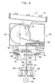
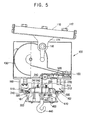
- FIGs. 2 to 5 are front and side views respectively showing inner configuration of the main body 100 and the moving: body 400 provided in the high mounted lamp equipment of the present invention.
- FIGs 2 and 4 show a state that the main body 100 and the moving body 400 are separated
- FIGs. 3 and 5 show a state that the main body 100 and the moving body 400 are combined each other.
- the main body 100 is installed to a ceiling of a factory by the support bracket 110, in which the support bracket 110 is combined to the H beam mounted to the ceiling of a factory by a bolt 112, and a side bracket 114 extended from the support bracket 110 is combined to a side of the main body 100 by another bolt 116.
- the support bracket 110 is mounted to an inclined ceiling, the main body 100 may be installed not to tilt by adjusting an angle between the main body 100 and the side bracket 114, as well shown in FIGs. 4 and 5 .
- the main body 100 has a space therein and a driving means for ascending and descending the moving body 400 is installed in that space.
- a motor 120 is mounted to an inner side of the main body 100, and a drum 130 coaxially combined to the motor 120 is also mounted in the main body 100.
- the drum 130 rotates by driving force from the motor 120 to wind or release the wire rope 140 around the drum 130.
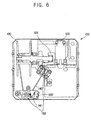
- a gearbox 125 (see FIG. 6 ) is installed between the motor 120 and the drum 130 to regulate a rotating speed of the drum 130.
- At least one guide pulley 150 (see FIG. 6 ) is installed in the main body 100.
- the guide pulley 150 guides a direction of the wire rope 140 wound around the drum 130 to be oriented vertically downward from a center of the main body 100.
- Number and shape of the guide pulley 150 may be modified as required, and not limited to a specific example.
- a casing 160 of a certain shape is fixed under the main body 100.
- the casing 160 has an open bottom so that the moving body 400 may enter into or exit from the casing 160, and an upper terminal unit 200 described below is installed in the casing 160.
- a stopper 300 described below is mounted in the casing 160, and a groove 161 is formed to the casing 160 to ensure a space where the stopper 300 may rotate.
- the stopper 300 and the groove 161 are described below in more detail.
- the upper terminal unit 200 is seated in the casing 160, and for this reason, a lower portion of the casing 160 is narrower than an upper portion thereof and the casing 160 has a projection 162 where the upper terminal unit 200 is seated.
- a guide rod 211 is mounted between the projection 162 of the casing 160 and a lower end of the main body 100, and a guide groove 210 is formed to the upper terminal unit 200 so that the guide rod 211 is inserted into.
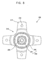
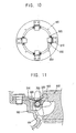
- four guide grooves 210 are formed at approximately 90°, as well shown in FIGs. 7 and 8 , which depict only the upper terminal unit 200.
- the upper terminal unit 200 has protruded support brackets 212 extended to four directions, and the guide grooves 210 are formed near an end of each protruded support bracket 212. And, a certain space 213 is formed between each protruded support bracket so that the stopper 300 is mounted and activated in the space 213.
- a center of a lower surface of the upper terminal unit 200 is flatly formed to have a disk shape with a constant diameter, and a through hole 220 is formed to a center of the upper terminal unit 200 so that the wire rope 140 may pass vertically through the upper terminal unit 200.
- An upper contact terminal 240 having certain size and area is formed on the disk-shaped flat portion of the lower surface of the upper terminal unit 200.
- the upper contact terminal 200 has two circular ring-shaped contact terminals 241, 242, which are respectively called as an inner contact terminal 241 and an outer contact terminal 242.
- Such inner and outer contact terminals 241, 242 are inserted into the upper terminal unit 200 with one end being bent, and then fixed by a combining member 260.
- the inner and outer contact terminals 241, 242 are electrically connected to a power source.
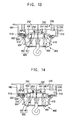
- a spring 250 may be installed to the inner and outer contact terminals 241, 242.
- This spring 250 presses the upper contact terminal 240 downward when the moving body 400 is ascended and then fixed with pushing up the upper terminal unit 200 as described below, so as to maintain contact with a lower contact terminal 420 described below more firmly.
- the spring 250 may be installed to both of the inner and outer contact terminals 241, 242, or may be installed to any one of them.
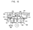
- FIGs. 13 to 15 show that the spring 250 is installed only to the inner contact terminal 241, and the spring 250 is inserted into a spring groove 252 formed at a lower surface of the upper terminal unit 200.
- An upper surface of the upper terminal unit 200 is spaced apart a predetermined distance from the main body 100, and the upper terminal unit 200 may move vertically along the guide rod 211.
- a spring 230 having certain elasticity is installed around the guide rod 211 between the main body 100 and the upper terminal unit 200 so as to elastically press the upper terminal unit 200 downward. Therefore, when the moving body 400 ascends, the upper terminal unit 200 is pushed by the lower contact terminal 420 mounted on the upper surface of the moving body 400 to move upward, and the upper terminal unit 200 is pressed by the spring 230 downward to maintain a contact state with the upper and lower contact terminals 240, 420.
- the stopper 300 is installed at an inner wall of the casing 160 in the space 213 formed between the protruded support brackets 212 of the upper terminal unit 200 so as to selectively hook or unhook the moving body 400.
- stoppers 300 are respectively combined with the brackets 310 mounted to the casing 160 at all spaces formed between protruded support brackets 212 of the upper terminal unit 200.
- the stopper 300 and the bracket 310 is connected by a hinge shaft so that the stopper 300 may rotate within a certain range
- a spring 330 is installed to the hinge shaft 330 so as to maintain the stopper 300 at a horizontal state when no external force is exerted.
- the spring 300 is fixed to the bracket 310 at one end and fixed to the stopper 300 at the other end.
- the casing 160 has sufficient space at an upper portion, but a lower portion has a narrowed width, which may interrupt rotation of the stopper 300. Therefore, a groove 161 is formed at the casing 160 below the stopper 300, that is the projection 162, so that the stopper 300 may rotate up to a certain range.
- an end of the stopper 300 preferably has a rounded shape so that the stopper 300 may be naturally pushed by a side of the moving body 400. Shapes of the stopper 300 and the groove 161 and a rotation range of the stopper 300 are well shown in FIG. 11 .
- any other structure may be adopted if it may fix the position of the moving body 400 suitably.
- a solenoid type driving unit which takes out or draws back a protrusion by electromagnetic field, may be applied instead of the stopper so that the protrusion is taken out to hook the moving body 400 when the moving body 400 is ascended and drawn back to unhook the moving body 400 when trying to descend the moving body 400.
- the moving body 400 working together with the main body 100 by the wire rope 140 may move from a position completely contacted with the upper terminal unit 200 to the ground.
- this moving body 400 has a lower terminal unit 410 at an upper surface.
- the lower terminal unit 410 includes a lower contact terminal on an upper surface in correspondence to the upper contact terminal 240 of the upper terminal unit 200.
- the lower contact terminal 420 also has circular ring-shaped inner and outer contact terminals 421, 422, similar to the upper contact terminal 240. These inner and outer contact terminals 421, 422 are inserted into the lower terminal unit 410 with end ends being bent, and an inserted portion of each contact terminal 421, 422 is combined with the lower terminal unit 410 by a separate combining member.
- a protrusion 430 is formed to an outer circumference of the moving body 400 to be in contact with the stopper 300.
- the protrusion 430 may push the stopper 300 to be rotated and act a role of fixing the position of the moving body 300 by being hooked to the stopper 300.
- the connecting unit 440 used to install a lamp is mounted under the moving body 400 and this connecting unit 440 may have a shape of hook, screw or the like. And, a wire groove 450 is formed to the moving body 400 to guide a wire connected to the lamp toward the lower contact terminal 420.
- an end of the wire rope 140 is fixed to an upper center of the moving body 400, and at this time the wire rope 140 should have so sufficient strength to endure load of the moving body during ascending and descending. And, the wire rope 140 should have a suitable length to possibly descend near the ground in consideration of surroundings in which the lamp is installed, and have flexibility so that it may be wound around the drum 130 by guidance of the guide pulley 150.
- a contact mark 141 to be detected by a first limit switch 500 described below is mounted at a predetermined position of the wire rope 140.
- the contact mark 141 is made by wrapping a surface of a part of the wire rope 140 with a lead bead or rubber packing, and comes in contact with the first limit switch 500 when the moving body 400 ascends to a predetermined height. And, if the contact mark 141 comes in contact with the first limit switch 500, the power supply to the motor 120 is connected and disconnected at a very short interval to wind up the wire rope 140 slowly.
- the time that the contact mark 141 comes in contact with the first limit switch 500 is when the lower contact terminal 420 of the moving body 400 reaches near the upper contact terminal 240 of the upper terminal unit 200, so that the moving body 400 ascends slowly from that time to contact the lower contact terminal 420 and the upper contact terminal 240 smoothly.
- Driving the motor 120 slowly as described above is realized only by connecting and disconnecting the power supply at a very short interval without using any current adjustment device. Therefore, such a driving method does not require other auxiliaries such as encoder or inverter to control rotation speed of the motor 120, which reduces manufacturing costs and makes the equipment more stable because of not using the encoder and the inverter, which are frequently malfunctioned.
- Such a contact mark may be also mounted to an uppermost portion of the wire rope 140.
- This contact mark 142 is wound around the drum 130 when the moving body 400 is at a high position, while unwound and detected by the first limit switch 500 when the moving body 400 descends to a predetermined height near the ground, and from that time the power supply to the motor 120 is connected and disconnected at a very short interval to move the lamp 10 slowly. In this case, because the moving body 400 moves more slowly at a position near the ground, it may prevent the lamp from collide with other structures installed on the ground.
- a second limit switch 510 is mounted to a certain position of the sidewall of the casing 160.
- the second limit switch 510 detects that the upper terminal 200 ascends and plays a role of releasing driving of the motor 120 and supplying power to the lamp. That is, the upper terminal unit 200 moves upward a little when the moving body 400 ascends so that the lower contact terminal 420 comes in contact with the upper contact terminal 240, and the second limit switch 510 detects the contact and stops driving of the motor 120.
- a third limit switch 520 is installed at a lower portion of the main body 100, and the third limit switch 520 detects a point of descending the moving body 400.
- the stopper 300 hooked upon the protrusion 430 should be released in order to descend the moving body 400, and for that reason the moving body 400 should be moved upward up to a predetermined height in advance.
- the upper terminal unit 200 is ascended together with pressing the spring 230 mounted to the guide rod 211.
- the third limit switch 520 transmits a signal for inversely driving the motor 120 to move the moving body 400 downward.
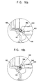
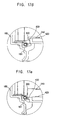
- FIGs. 16a to 16e and 17a to 17g respectively show the process that the moving body 400 ascends to be hooked by the stopper 300 and the process that the moving body 400 is unhooked from the stopper 300 to descend. Now, operational principles of each limit switch and the stopper are described in detail, referring to those figures.
- the moving body 400 In the ascending process first, the moving body 400 continuously ascends until the contact mark 141 of the wire rope 140 comes in contact with the first limit switch 500, and from that time the power supply to the motor 120 is repeatedly connected and disconnected at a very short interval so that the moving body 400 ascends slowly. If the moving body 400 ascends more, the protrusion 430 of the moving body 400 comes in contact with the stopper 300 at a horizontal state as shown in FIG. 16a . In this state, the moving body 400 ascends more as shown in FIG. 16b , so that the protrusion 430 pushes up the stopper 300 and the lower contact terminal 420 of the lower terminal unit 410 contacts with the upper contact terminal 240 of the upper terminal unit 200.
- the moving body 400 continuously ascends and pushes up the upper terminal unit 200 as shown in FIG. 16c , and the second limit switch 510 detects it just before the protrusion 430 is deviated from the stopper 300 and stops driving of the motor 120.
- the protrusion 430 becomes deviated from the stopper 300 as shown in FIG. 16d due to its inertia.
- the motor 120 is instantaneously driven inversely so that the protrusion 430 moves downward and is then hooked upon the stopper 300 as shown in FIG. 17a .
- the upper terminal unit 200 is pressed down by the spring 230 mounted to the guide rod 211 so that the upper and lower contact terminals 240, 420 are firmly contacted each other.
- the power source is supplied to the lamp 10 through the contact terminals 240, 420 according to the signal of the second limit switch 510 so as to turn on the lamp 10.
- the power source supplied to the lamp 10 is blocked as soon as a descending signal is received.
- the motor 120 is driven to draw up the moving body 400 (see FIGS. 17b ).
- the motor 120 keeps ascending the moving body 400 until the stopper 300 is entirely deviated from the side of the moving body 400, and the upper terminal unit 200 is ascended together to a position approximately contacting with the lower surface of the main body 100.
- the stopper 300 is entirely deviated from the side of the moving body 400 and recovers its horizontal state due to the spring 330.
- the upper terminals unit 200 comes in contact with the third limit switch 520 mounted to the lower surface of the main body 100, and from this time, the motor 120 is driven inversely according to a detect signal of the third limit switch 520 to move the moving body 400 downward.
- the upper terminal unit 200 is also moved downward together by restoring force of the spring 230 with guidance of the guide rod 211. Therefore, the moving body 400 descends and a lower end of the moving body 400 then comes in contact with the stopper 400 as shown in FIG. 17d .
- the motor 120 is continuously driven so that the wire rope 140 keeps unwinding from the drum 130 to move the moving body 400 downward by gravity, and therefore the side and the protrusion 430 of the moving body 400 pass over the stopper 300 and the stopper 300 is pushed to pivotally move toward the groove 161 of the casing 160.
- the upper terminal unit 200 is seated on the projection 162 of the casing 160 to stop at a predetermined position, and therefore the upper contact terminal 240 of the upper terminal unit 200 becomes separated from the lower contact terminal 420 of the lower terminal unit 410.
- the stopper 300 recovers its horizontal state owing to restoring force of the spring 330.
- the upper and lower contact terminals 240,420 are described to respectively have two corresponding circular ring-shaped contact terminals 241,242 and 421,422, This configuration is to ensure stable contact between the terminals because each circular ring-shaped contact terminal 241,242 and 421,422 is surface-contacted.
- the high mounted lamp equipment of the present invention as above may be installed to a building such as gymnasium, factory, wedding hall, hotel lobby and so on, and to a streetlight. In this case, there can be installed just one lamp or more depending on circumstance. In some cases, several thousands of lamps are installed together. Therefore, the controller 900 for manipulating the high mounted lamp equipment of the present invention is preferably configured so that a user may handle a plurality of high mounted lamp equipments at the same time. For example, it is possible that, after endowing a serial number to each lamp equipment, the user selects a desired high mounted lamp equipment and then deals with only the equipment. In addition, the controller 900 may also have a function of handling all of the high mounted lamp equipments installed in a building. Such a controller 900 can be operated in wire or wireless, and in case of a wireless controller, a transmitter should be provided to the controller 900 and a receiver for receiving a radio signal from the controller should be also provided to each high mounted lamp equipment.
- the high mounted lamp equipment of the present invention as described above may move the lamp, mounted at a high position such as a ceiling of a building or a streetlight, to the ground with only one wire rope, so giving advantages of easy repair and change.
- the high mounted lamp equipment of the present invention is structurally stable and lack of breakdown because the protrusion of the moving body may be combined and released with the main body by working together with the stopper and the stopper may support the moving body stably when being combined with the main body.
- the upper and lower terminal units may be stably surface-contacted without deviation of the terminals, and the contact between the terminals can be stably maintained by pressing the terminals with the spring.
Landscapes
- Engineering & Computer Science (AREA)
- General Engineering & Computer Science (AREA)
- Non-Portable Lighting Devices Or Systems Thereof (AREA)
- Arrangement Of Elements, Cooling, Sealing, Or The Like Of Lighting Devices (AREA)
- Lighting Device Outwards From Vehicle And Optical Signal (AREA)
Claims (8)
- Einrichtung für eine in großer Höhe montierte Lampe mit Auf und Abwärtsbewegungsfunktionen, die Folgendes umfasst:einen Hauptkörper (100), der in einer bestimmten Höhe installiert ist und eine Trommel (130) zum Wickeln eines Drahtseils (140) und einen Motor (120) zum Drehen der Trommel (130) aufweist;ein Gehäuse (160), das unter dem Hauptkörper (100) montiert ist und einen offenen Boden hat;eine obere Anschlusseinheit (200), die in dem Gehäuse (160) vom Hauptkörper (100) beabstandet installiert ist und wenigstens einen oberen Kontaktanschluss (240) am unteren Ende hat;einen bewegten Körper (400), der mit dem Drahtseil (140) verbunden ist, das von dem Motor (120) vertikal bewegt werden kann, wobei der bewegte Körper (400) eine Verbindungseinheit (440) zum Installieren einer Lampe daran und einen unteren Kontaktanschluss (420) aufweist, der an einem oberen Ende davon montiert ist, das dem oberen Kontaktanschluss (240) entspricht; undeinen Stopper (300), der drehbar an dem Gehäuse (160) montiert ist, um mit einer Feder (330) einen horizontalen Zustand zu halten,wobei ein Vorsprung (430) auf einer Seite des bewegten Körpers (400) an einer Position ausgebildet ist, die mit dem Stopper (300) in Teilkontakt kommt, so dass der Vorsprung (430) am Stopper (300) eingehakt wird, wenn nach einer Aufwärtsbewegung über den Stopper (300) hinaus eine Abwärtsbewegung erfolgt, um die Höhe des bewegten Körpers (400) zu fixieren, während der Vorsprung (430) vom Stopper (300) gelöst wird, wenn er sich über den Stopper (300) hinaus bewegt, so dass sich der bewegte Körper (400) abwärts bewegen kann, dadurch gekennzeichnet, dass die an der oberen Anschlusseinheit (200) ausgebildeten oberen Kontaktanschlüsse (240) innere und äußere kreisringförmige Kontaktanschlüsse (241, 242) aufweisen und die an dem bewegten Körper (400) ausgebildeten unteren Kontaktanschlüsse (420) innere und äußere kreisringförmige Kontaktanschlüsse (421, 422) an den entsprechenden oberen Kontaktanschlüssen (240) aufweisen.
- Einrichtung für eine in großer Höhe angebrachte Lampe mit Aufwärts- und Abwärtsbewegungsfunktionen nach Anspruch 1,
wobei eine Kontaktmarke (141) an einer vorbestimmten Position des Drahtseils (140) montiert ist und ein erster Endschalter (500) am Hauptkörper (100) installiert ist, der mit der Kontaktmarke (141) in Kontakt kommt, wenn der bewegte Körper (400) die obere Anschlusseinheit (200) erreicht, um den bewegten Körper (400) langsam durch wiederholtes Zuschalten/Abtrennen der Stromversorgung des Motors (120) in kurzen Intervallen anzutreiben, wenn der erste Endschalter (500) die Kontaktmarke (141) während der Aufwärtsbewegung des bewegten Körpers (400) feststellt. - Einrichtung für eine in großer Höhe angebrachte Lampe mit Aufwärts- und Abwärtsbewegungsfunktionen nach Anspruch 1 oder 2,
wobei eine zusätzliche Kontaktmarke (142) einer vorbestimmten Länge an einem oberen Ende des Drahtseils (140) montiert wird, so dass der erste Endschalter (500) mit der zusätzlichen Kontaktmarke (142) ab dem Zeitpunkt in Kontakt kommt, an dem sich der bewegte Körper (400) dem Boden bei der Abwärtsbewegung des bewegten Körpers (400) nähert und durch wiederholtes Zuschalten/Abtrennen der Stromversorgung des Motors (120) bewirkt, dass sich der bewegte Körper (400) langsam abwärts bewegt und dann stoppt. - Einrichtung für eine in großer Höhe angebrachte Lampe mit Aufwärts- und Abwärtsbewegungsfunktionen nach Anspruch 1, 2 oder 3,
wobei ein Führungsstab (211) zwischen dem Hauptkörper (100) und dem Gehäuse (160) montiert ist, der so durch die obere Anschlusseinheit (200) passiert, dass sich die obere Anschlusseinheit (200) vertikal entlang dem Führungsstab (211) bewegt, und
wobei eine Feder (230) an dem Führungsstab (211) zwischen der oberen Anschlusseinheit (200) und dem Hauptkörper (100) installiert ist, um die obere Anschlusseinheit (200) nach unten zu drücken. - Einrichtung für eine in großer Höhe angebrachte Lampe mit Aufwärts- und Abwärtsbewegungsfunktionen nach Anspruch 3 oder 4,
wobei ein zweiter Endschalter (510) an dem Gehäuse (160) installiert ist, um zu erkennen, wenn sich die obere Anschlusseinheit (200) bis in eine vorbestimmte Höhe nach oben bewegt, um einen Zeitpunkt zu ermitteln, an dem der Vorsprung (430) des bewegten Körpers (400) vom Stopper (300) abweicht, und
wobei der Motor (120) nach dem Empfang eines Erkennungssignals des zweiten Endschalters (510) gestoppt wird. - Einrichtung für eine in großer Höhe angebrachte Lampe mit Aufwärts- und Abwärtsbewegungsfunktionen nach Anspruch 5,
wobei der Motor (120), der durch das Erkennungssignal des zweiten Endschalters (510) gestoppt wird, vorübergehend umgekehrt angetrieben wird, sobald der Vorsprung (430) vom Stopper (300) abweicht, um den bewegten Körper (400) geringfügig nach unten zu bewegen. - Einrichtung für eine in großer Höhe angebrachte Lampe mit Aufwärts- und Abwärtsbewegungsfunktionen nach einem der Ansprüche 1 bis 6,
wobei ein dritter Endschalter (520) unter dem Hauptkörper (100) so installiert ist, dass er mit der oberen Anschlusseinheit (200) in Kontakt kommt, wenn sich die obere Anschlusseinheit (200) nach oben bewegt, so dass der Stopper (300) völlig von der Seite des bewegten Körpers (400) abweicht, und
wobei der Motor (120) nach dem Empfang eines Erkennungssignals des dritten Endschalters (520) umgekehrt angetrieben wird, um den bewegten Körper (400) nach unten zu bewegen. - Einrichtung für eine in großer Höhe angebrachte Lampe mit Aufwärts- und Abwärtsbewegungsfunktionen nach einem der Ansprüche 1 bis 7,
wobei eine Feder (250) an wenigstens einem der oberen Kontaktanschlüsse (240) installiert ist, die an der oberen Anschlusseinheit (200) montiert ist, um den entsprechenden oberen Kontaktanschluss in Richtung auf den bewegten Körper (400) zu drücken.
Applications Claiming Priority (7)
| Application Number | Priority Date | Filing Date | Title |
|---|---|---|---|
| KR2001000918U | 2001-01-12 | ||
| KR2020010000918U KR200227951Y1 (ko) | 2001-01-12 | 2001-01-12 | 자동 승하강장치가 구비된 고소 조명등. |
| KR2001018081U | 2001-06-16 | ||
| KR2020010018082U KR200248459Y1 (ko) | 2001-06-16 | 2001-06-16 | 승하강장치가 구비된 고소 조명등의 접점구조. |
| KR2020010018081U KR200248458Y1 (ko) | 2001-06-16 | 2001-06-16 | 승하강장치가 구비된 고소 조명등용 스톱퍼. |
| KR2001018082U | 2001-06-16 | ||
| PCT/KR2002/000046 WO2002055931A1 (en) | 2001-01-12 | 2002-01-11 | Equipment for highly mounted lamp having ascending and descending function |
Publications (3)
| Publication Number | Publication Date |
|---|---|
| EP1384030A1 EP1384030A1 (de) | 2004-01-28 |
| EP1384030A4 EP1384030A4 (de) | 2007-04-04 |
| EP1384030B1 true EP1384030B1 (de) | 2010-11-17 |
Family
ID=27350390
Family Applications (1)
| Application Number | Title | Priority Date | Filing Date |
|---|---|---|---|
| EP02715886A Expired - Lifetime EP1384030B1 (de) | 2001-01-12 | 2002-01-11 | Einrichtung für in grosser höhe angebrachte lampe mit aufwärts- und abwärtsbewegungsfunktion |
Country Status (7)
| Country | Link |
|---|---|
| US (1) | US7033048B2 (de) |
| EP (1) | EP1384030B1 (de) |
| JP (1) | JP2004518245A (de) |
| CN (1) | CN1279308C (de) |
| AT (1) | ATE488733T1 (de) |
| DE (1) | DE60238314D1 (de) |
| WO (1) | WO2002055931A1 (de) |
Cited By (1)
| Publication number | Priority date | Publication date | Assignee | Title |
|---|---|---|---|---|
| DE102014101729A1 (de) | 2014-01-22 | 2015-07-23 | Alfred Korsch | Vorrichtung zum Anheben und Absenken eines Beleuchtungskörpers od. dgl. relativ zu einer ortsfest anzubringenden, nach unten offenen Halterung |
Families Citing this family (28)
| Publication number | Priority date | Publication date | Assignee | Title |
|---|---|---|---|---|
| CN2859214Y (zh) * | 2005-09-16 | 2007-01-17 | 邱国平 | 一种新型可升降式吊灯 |
| US7494254B2 (en) * | 2006-02-14 | 2009-02-24 | Rogers Elizabeth M | Pull down light fixture |
| WO2007133032A1 (en) * | 2006-05-16 | 2007-11-22 | Seong-Don Choi | Electric connecting device and electric establishment with electric connecting device |
| US20080037264A1 (en) * | 2006-08-08 | 2008-02-14 | Craig Delane Bennett | Fixture lowering device |
| CN2937821Y (zh) * | 2007-01-18 | 2007-08-22 | 吴孝好 | 旋转升降式吊灯器 |
| US20080193291A1 (en) * | 2007-02-12 | 2008-08-14 | Ware Randall C | Descendable Ceiling Fixture |
| US20100227499A1 (en) * | 2009-03-09 | 2010-09-09 | Anthony Ramos | Hanging fixture maintenance device |
| GB0904522D0 (en) * | 2009-03-17 | 2009-04-29 | Bond Peter M Lord | Bonds hoisting system |
| US8337037B2 (en) * | 2010-01-20 | 2012-12-25 | Larry D. Hopkins | Mounting bracket |
| IT1399810B1 (it) * | 2010-01-28 | 2013-05-03 | Denti | Dispositivo sali/scendi perfezionato per elementi a sospensione. |
| NO331953B1 (no) * | 2011-04-14 | 2012-05-14 | Universel As | Anordning, system og anvendelser for senking og heving av minst ±n stromdrevet gjenstand |
| US8733985B2 (en) | 2012-08-10 | 2014-05-27 | GLS Innovations, L.L.C. | Horizontally and vertically mountable fixture extension that can be lowered for service |
| US9587809B2 (en) * | 2013-10-04 | 2017-03-07 | Thomas Nevitt | Light replacing apparatus for replacing bulbs in street lamps |
| CN103697339B (zh) * | 2013-12-31 | 2015-11-18 | 苏州承腾电子科技有限公司 | 一种户外led应急灯 |
| KR101479697B1 (ko) * | 2014-04-11 | 2015-01-07 | (주)오티에스 | Cctv 카메라 유지보수용 오토리프트 장치 |
| PL3115687T3 (pl) * | 2015-07-06 | 2018-11-30 | Reel Tech Co. Ltd. | Urządzenie podnoszące dla wysoko montowanego wyposażenia |
| US10773930B2 (en) | 2016-07-27 | 2020-09-15 | Jeong-Hoon SHIN | Home-delivered article loading device for drone |
| EP3450385B1 (de) * | 2017-08-31 | 2020-07-08 | Dmitrijs Volohovs | Winde |
| US10145543B1 (en) * | 2017-08-31 | 2018-12-04 | Sinowell (Shanghai) Co., Ltd. | Device for adjusting height of suspended lamp |
| US11261065B2 (en) | 2017-10-27 | 2022-03-01 | Reel Tech Co., Ltd. | Lifting apparatus for highly-mounted device |
| US11247881B2 (en) * | 2017-10-27 | 2022-02-15 | Reel Tech Co., Ltd. | Lifting apparatus for highly-mounted device and control method thereof |
| KR102050020B1 (ko) * | 2017-10-27 | 2019-11-28 | 주식회사 릴테크 | 고소 설치 기기용 승강장치 및 그 제어 방법 |
| US11072518B2 (en) | 2018-12-06 | 2021-07-27 | Dmitrijs Volohovs | Winch |
| US10533735B1 (en) | 2019-05-10 | 2020-01-14 | Alireza Sokhanvari | Breaking an electrical connection before lowering a lighting fixture or other electricity powered apparatus from a remote distance such as a ceiling |
| KR102093072B1 (ko) * | 2019-08-23 | 2020-05-29 | 진 태 임 | 자동승강 장치 |
| CN113280287B (zh) * | 2020-02-19 | 2024-05-24 | 徐文艳 | 一种室内设计用装饰灯 |
| CN111442204B (zh) * | 2020-05-15 | 2024-09-10 | 杭州索恩机械有限公司 | 一种照明装置 |
| CN118391630A (zh) * | 2024-06-24 | 2024-07-26 | 江苏轩朗照明电器有限公司 | 一种多功能led路灯照明装置 |
Family Cites Families (15)
| Publication number | Priority date | Publication date | Assignee | Title |
|---|---|---|---|---|
| US4429355A (en) * | 1978-09-18 | 1984-01-31 | Union Metal Manufacturing Company | Luminaire raising and lowering system |
| JPS636808Y2 (de) * | 1980-05-29 | 1988-02-26 | ||
| SE431175B (sv) | 1982-11-30 | 1984-01-23 | Tarkett Ab | Sett for fanerskerning |
| US4851980A (en) * | 1988-06-29 | 1989-07-25 | Meade Industrial Services, Inc. | Double drum level winding rope lift mechanism for luminaires on high lighting masts |
| JPH0294312A (ja) | 1988-09-30 | 1990-04-05 | Toshiba Lighting & Technol Corp | 昇降形照明装置 |
| DE3928359C1 (de) * | 1989-08-28 | 1991-01-24 | Maschinenfabrik Reinhausen Gmbh, 8400 Regensburg, De | |
| US5105349A (en) * | 1990-09-24 | 1992-04-14 | Falls John W | Motorized chandelier lift system |
| KR950006818Y1 (ko) * | 1993-07-07 | 1995-08-21 | 김재홍 | 회전브러시가 장착된 진공청소기 |
| KR0138345B1 (ko) | 1993-08-18 | 1998-05-15 | 김광호 | 디지탈 자동주파수조정(afc) 방법 및 장치 |
| JPH08192995A (ja) * | 1995-01-18 | 1996-07-30 | Tec Corp | 電動昇降装置 |
| DE69625197T2 (de) | 1995-06-07 | 2003-09-25 | Chromatics Color Sciences International, Inc. | Verfahren und vorrichtung zum nachweis und messen von zuständen,welche die farbe beeinflussen |
| DE69505514T2 (de) * | 1995-06-09 | 1999-06-24 | Matsushita Electric Works, Ltd., Kadoma, Osaka | Hebevorrichtung für einen Beleuchtungskörper |
| US5570546A (en) * | 1995-07-31 | 1996-11-05 | American High Mast Systems, Inc. | System for raising and lowering communications equipment |
| JPH10203787A (ja) | 1997-01-24 | 1998-08-04 | Tec Corp | 電動昇降装置 |
| KR200248028Y1 (ko) * | 1999-03-22 | 2001-10-27 | 박천돈 | 조명탑의 안전걸쇠장치 |
-
2002
- 2002-01-11 EP EP02715886A patent/EP1384030B1/de not_active Expired - Lifetime
- 2002-01-11 WO PCT/KR2002/000046 patent/WO2002055931A1/en active Application Filing
- 2002-01-11 CN CNB028036212A patent/CN1279308C/zh not_active Expired - Lifetime
- 2002-01-11 JP JP2002556546A patent/JP2004518245A/ja active Pending
- 2002-01-11 AT AT02715886T patent/ATE488733T1/de active
- 2002-01-11 DE DE60238314T patent/DE60238314D1/de not_active Expired - Lifetime
-
2003
- 2003-07-14 US US10/619,984 patent/US7033048B2/en not_active Expired - Lifetime
Cited By (2)
| Publication number | Priority date | Publication date | Assignee | Title |
|---|---|---|---|---|
| DE102014101729A1 (de) | 2014-01-22 | 2015-07-23 | Alfred Korsch | Vorrichtung zum Anheben und Absenken eines Beleuchtungskörpers od. dgl. relativ zu einer ortsfest anzubringenden, nach unten offenen Halterung |
| DE102014101729B4 (de) * | 2014-01-22 | 2016-06-16 | Alfred Korsch | Vorrichtung zum Anheben und Absenken eines Beleuchtungskörpers od. dgl. relativ zu einer ortsfest anzubringenden, nach unten offenen Halterung |
Also Published As
| Publication number | Publication date |
|---|---|
| JP2004518245A (ja) | 2004-06-17 |
| ATE488733T1 (de) | 2010-12-15 |
| US20040012969A1 (en) | 2004-01-22 |
| EP1384030A1 (de) | 2004-01-28 |
| DE60238314D1 (de) | 2010-12-30 |
| CN1279308C (zh) | 2006-10-11 |
| CN1484745A (zh) | 2004-03-24 |
| US7033048B2 (en) | 2006-04-25 |
| EP1384030A4 (de) | 2007-04-04 |
| WO2002055931A1 (en) | 2002-07-18 |
Similar Documents
| Publication | Publication Date | Title |
|---|---|---|
| EP1384030B1 (de) | Einrichtung für in grosser höhe angebrachte lampe mit aufwärts- und abwärtsbewegungsfunktion | |
| KR101056847B1 (ko) | 고소조명 승강장치 | |
| KR101184989B1 (ko) | 조명등 승강 장치 | |
| KR101133858B1 (ko) | 천장 설치형 중량물용 승강 장치 | |
| US11247881B2 (en) | Lifting apparatus for highly-mounted device and control method thereof | |
| US20220196226A1 (en) | Luminaire apparatus having air cleaner attached thereto, which is connected by wires and cables so as to be vertically movable | |
| KR101589715B1 (ko) | 고소 설치 기기용 승강장치 | |
| KR102050020B1 (ko) | 고소 설치 기기용 승강장치 및 그 제어 방법 | |
| KR200326792Y1 (ko) | 등기구 승강 장치 | |
| KR101026555B1 (ko) | 고소조명 승하강장치 | |
| KR20050082833A (ko) | 천장설치용 조명등 승강장치 | |
| KR20050082842A (ko) | 천장설치용 조명등 승강장치 | |
| CN114641446B (zh) | 智能高处安装设备升降装置及其控制方法 | |
| ES2354415T3 (es) | Equipamiento para lámpara montada en altura con función de ascenso y descenso. | |
| KR100602613B1 (ko) | 승하강수단이 구비된 조명등 | |
| JP3134683B2 (ja) | 屋外用昇降式照明器具 | |
| KR200248459Y1 (ko) | 승하강장치가 구비된 고소 조명등의 접점구조. | |
| CN110630940B (zh) | 灯具 | |
| KR100454819B1 (ko) | 승하강장치가 구비된 고소 조명등용 스톱퍼. | |
| KR960009270Y1 (ko) | 전동식 산업용 승강조명장치 | |
| KR101934868B1 (ko) | 와이어가 연결되는 결합유도돌기를 구비한 조명등 리프팅 장치 | |
| KR200248458Y1 (ko) | 승하강장치가 구비된 고소 조명등용 스톱퍼. | |
| KR20020097062A (ko) | 승하강장치가 구비된 고소 조명등의 접점구조. | |
| KR20040077642A (ko) | 등기구 승강 장치 | |
| KR101503584B1 (ko) | 일정구간만 조명을 켜서 승하강할 수 있는 조명 승강장치 |
Legal Events
| Date | Code | Title | Description |
|---|---|---|---|
| PUAI | Public reference made under article 153(3) epc to a published international application that has entered the european phase |
Free format text: ORIGINAL CODE: 0009012 |
|
| 17P | Request for examination filed |
Effective date: 20030811 |
|
| AK | Designated contracting states |
Kind code of ref document: A1 Designated state(s): AT BE CH CY DE DK ES FI FR GB GR IE IT LI LU MC NL PT SE TR |
|
| AX | Request for extension of the european patent |
Extension state: AL LT LV MK RO SI |
|
| A4 | Supplementary search report drawn up and despatched |
Effective date: 20070302 |
|
| 17Q | First examination report despatched |
Effective date: 20070730 |
|
| GRAP | Despatch of communication of intention to grant a patent |
Free format text: ORIGINAL CODE: EPIDOSNIGR1 |
|
| GRAS | Grant fee paid |
Free format text: ORIGINAL CODE: EPIDOSNIGR3 |
|
| GRAA | (expected) grant |
Free format text: ORIGINAL CODE: 0009210 |
|
| RAP1 | Party data changed (applicant data changed or rights of an application transferred) |
Owner name: SIN, JEONG-HOON |
|
| RIN1 | Information on inventor provided before grant (corrected) |
Inventor name: SIN, JEONG-HOON |
|
| AK | Designated contracting states |
Kind code of ref document: B1 Designated state(s): AT BE CH CY DE DK ES FI FR GB GR IE IT LI LU MC NL PT SE TR |
|
| AX | Request for extension of the european patent |
Extension state: RO SI |
|
| REG | Reference to a national code |
Ref country code: GB Ref legal event code: FG4D |
|
| REG | Reference to a national code |
Ref country code: CH Ref legal event code: EP |
|
| REG | Reference to a national code |
Ref country code: IE Ref legal event code: FG4D |
|
| REF | Corresponds to: |
Ref document number: 60238314 Country of ref document: DE Date of ref document: 20101230 Kind code of ref document: P |
|
| REG | Reference to a national code |
Ref country code: CH Ref legal event code: NV Representative=s name: SERVOPATENT GMBH |
|
| REG | Reference to a national code |
Ref country code: NL Ref legal event code: T3 |
|
| REG | Reference to a national code |
Ref country code: ES Ref legal event code: FG2A Effective date: 20110302 |
|
| PG25 | Lapsed in a contracting state [announced via postgrant information from national office to epo] |
Ref country code: PT Free format text: LAPSE BECAUSE OF FAILURE TO SUBMIT A TRANSLATION OF THE DESCRIPTION OR TO PAY THE FEE WITHIN THE PRESCRIBED TIME-LIMIT Effective date: 20110317 Ref country code: CY Free format text: LAPSE BECAUSE OF FAILURE TO SUBMIT A TRANSLATION OF THE DESCRIPTION OR TO PAY THE FEE WITHIN THE PRESCRIBED TIME-LIMIT Effective date: 20101117 Ref country code: SE Free format text: LAPSE BECAUSE OF FAILURE TO SUBMIT A TRANSLATION OF THE DESCRIPTION OR TO PAY THE FEE WITHIN THE PRESCRIBED TIME-LIMIT Effective date: 20101117 Ref country code: FI Free format text: LAPSE BECAUSE OF FAILURE TO SUBMIT A TRANSLATION OF THE DESCRIPTION OR TO PAY THE FEE WITHIN THE PRESCRIBED TIME-LIMIT Effective date: 20101117 |
|
| PG25 | Lapsed in a contracting state [announced via postgrant information from national office to epo] |
Ref country code: GR Free format text: LAPSE BECAUSE OF FAILURE TO SUBMIT A TRANSLATION OF THE DESCRIPTION OR TO PAY THE FEE WITHIN THE PRESCRIBED TIME-LIMIT Effective date: 20110218 |
|
| PG25 | Lapsed in a contracting state [announced via postgrant information from national office to epo] |
Ref country code: BE Free format text: LAPSE BECAUSE OF FAILURE TO SUBMIT A TRANSLATION OF THE DESCRIPTION OR TO PAY THE FEE WITHIN THE PRESCRIBED TIME-LIMIT Effective date: 20101117 |
|
| PG25 | Lapsed in a contracting state [announced via postgrant information from national office to epo] |
Ref country code: MC Free format text: LAPSE BECAUSE OF NON-PAYMENT OF DUE FEES Effective date: 20110131 Ref country code: DK Free format text: LAPSE BECAUSE OF FAILURE TO SUBMIT A TRANSLATION OF THE DESCRIPTION OR TO PAY THE FEE WITHIN THE PRESCRIBED TIME-LIMIT Effective date: 20101117 |
|
| PLBE | No opposition filed within time limit |
Free format text: ORIGINAL CODE: 0009261 |
|
| STAA | Information on the status of an ep patent application or granted ep patent |
Free format text: STATUS: NO OPPOSITION FILED WITHIN TIME LIMIT |
|
| 26N | No opposition filed |
Effective date: 20110818 |
|
| REG | Reference to a national code |
Ref country code: IE Ref legal event code: MM4A |
|
| REG | Reference to a national code |
Ref country code: DE Ref legal event code: R097 Ref document number: 60238314 Country of ref document: DE Effective date: 20110818 |
|
| PG25 | Lapsed in a contracting state [announced via postgrant information from national office to epo] |
Ref country code: IE Free format text: LAPSE BECAUSE OF NON-PAYMENT OF DUE FEES Effective date: 20110111 |
|
| PG25 | Lapsed in a contracting state [announced via postgrant information from national office to epo] |
Ref country code: LU Free format text: LAPSE BECAUSE OF NON-PAYMENT OF DUE FEES Effective date: 20110111 |
|
| PG25 | Lapsed in a contracting state [announced via postgrant information from national office to epo] |
Ref country code: TR Free format text: LAPSE BECAUSE OF FAILURE TO SUBMIT A TRANSLATION OF THE DESCRIPTION OR TO PAY THE FEE WITHIN THE PRESCRIBED TIME-LIMIT Effective date: 20101117 |
|
| REG | Reference to a national code |
Ref country code: FR Ref legal event code: PLFP Year of fee payment: 15 |
|
| PGFP | Annual fee paid to national office [announced via postgrant information from national office to epo] |
Ref country code: NL Payment date: 20160111 Year of fee payment: 15 |
|
| PGFP | Annual fee paid to national office [announced via postgrant information from national office to epo] |
Ref country code: ES Payment date: 20160113 Year of fee payment: 15 |
|
| REG | Reference to a national code |
Ref country code: FR Ref legal event code: PLFP Year of fee payment: 16 |
|
| REG | Reference to a national code |
Ref country code: NL Ref legal event code: MM Effective date: 20170201 |
|
| PG25 | Lapsed in a contracting state [announced via postgrant information from national office to epo] |
Ref country code: NL Free format text: LAPSE BECAUSE OF NON-PAYMENT OF DUE FEES Effective date: 20170201 |
|
| REG | Reference to a national code |
Ref country code: FR Ref legal event code: PLFP Year of fee payment: 17 |
|
| PGFP | Annual fee paid to national office [announced via postgrant information from national office to epo] |
Ref country code: CH Payment date: 20180115 Year of fee payment: 17 |
|
| PG25 | Lapsed in a contracting state [announced via postgrant information from national office to epo] |
Ref country code: ES Free format text: LAPSE BECAUSE OF NON-PAYMENT OF DUE FEES Effective date: 20170112 |
|
| PGFP | Annual fee paid to national office [announced via postgrant information from national office to epo] |
Ref country code: IT Payment date: 20180122 Year of fee payment: 17 |
|
| REG | Reference to a national code |
Ref country code: ES Ref legal event code: FD2A Effective date: 20181114 |
|
| PGFP | Annual fee paid to national office [announced via postgrant information from national office to epo] |
Ref country code: GB Payment date: 20190109 Year of fee payment: 18 Ref country code: FR Payment date: 20190111 Year of fee payment: 18 Ref country code: DE Payment date: 20190108 Year of fee payment: 18 |
|
| PGFP | Annual fee paid to national office [announced via postgrant information from national office to epo] |
Ref country code: AT Payment date: 20190109 Year of fee payment: 18 |
|
| REG | Reference to a national code |
Ref country code: CH Ref legal event code: PL |
|
| PG25 | Lapsed in a contracting state [announced via postgrant information from national office to epo] |
Ref country code: LI Free format text: LAPSE BECAUSE OF NON-PAYMENT OF DUE FEES Effective date: 20190131 Ref country code: CH Free format text: LAPSE BECAUSE OF NON-PAYMENT OF DUE FEES Effective date: 20190131 |
|
| PG25 | Lapsed in a contracting state [announced via postgrant information from national office to epo] |
Ref country code: IT Free format text: LAPSE BECAUSE OF NON-PAYMENT OF DUE FEES Effective date: 20190111 |
|
| REG | Reference to a national code |
Ref country code: DE Ref legal event code: R119 Ref document number: 60238314 Country of ref document: DE |
|
| REG | Reference to a national code |
Ref country code: AT Ref legal event code: MM01 Ref document number: 488733 Country of ref document: AT Kind code of ref document: T Effective date: 20200111 |
|
| GBPC | Gb: european patent ceased through non-payment of renewal fee |
Effective date: 20200111 |
|
| PG25 | Lapsed in a contracting state [announced via postgrant information from national office to epo] |
Ref country code: GB Free format text: LAPSE BECAUSE OF NON-PAYMENT OF DUE FEES Effective date: 20200111 Ref country code: DE Free format text: LAPSE BECAUSE OF NON-PAYMENT OF DUE FEES Effective date: 20200801 Ref country code: FR Free format text: LAPSE BECAUSE OF NON-PAYMENT OF DUE FEES Effective date: 20200131 |
|
| PG25 | Lapsed in a contracting state [announced via postgrant information from national office to epo] |
Ref country code: AT Free format text: LAPSE BECAUSE OF NON-PAYMENT OF DUE FEES Effective date: 20200111 |