EP1383209A1 - Connecteur coaxial angulaire - Google Patents
Connecteur coaxial angulaire Download PDFInfo
- Publication number
- EP1383209A1 EP1383209A1 EP03013484A EP03013484A EP1383209A1 EP 1383209 A1 EP1383209 A1 EP 1383209A1 EP 03013484 A EP03013484 A EP 03013484A EP 03013484 A EP03013484 A EP 03013484A EP 1383209 A1 EP1383209 A1 EP 1383209A1
- Authority
- EP
- European Patent Office
- Prior art keywords
- coaxial connector
- shell
- connector according
- metal sleeve
- plastic body
- Prior art date
- Legal status (The legal status is an assumption and is not a legal conclusion. Google has not performed a legal analysis and makes no representation as to the accuracy of the status listed.)
- Withdrawn
Links
Images


Classifications
-
- H—ELECTRICITY
- H01—ELECTRIC ELEMENTS
- H01R—ELECTRICALLY-CONDUCTIVE CONNECTIONS; STRUCTURAL ASSOCIATIONS OF A PLURALITY OF MUTUALLY-INSULATED ELECTRICAL CONNECTING ELEMENTS; COUPLING DEVICES; CURRENT COLLECTORS
- H01R24/00—Two-part coupling devices, or either of their cooperating parts, characterised by their overall structure
- H01R24/38—Two-part coupling devices, or either of their cooperating parts, characterised by their overall structure having concentrically or coaxially arranged contacts
- H01R24/40—Two-part coupling devices, or either of their cooperating parts, characterised by their overall structure having concentrically or coaxially arranged contacts specially adapted for high frequency
- H01R24/54—Intermediate parts, e.g. adapters, splitters or elbows
- H01R24/545—Elbows
-
- H—ELECTRICITY
- H01—ELECTRIC ELEMENTS
- H01R—ELECTRICALLY-CONDUCTIVE CONNECTIONS; STRUCTURAL ASSOCIATIONS OF A PLURALITY OF MUTUALLY-INSULATED ELECTRICAL CONNECTING ELEMENTS; COUPLING DEVICES; CURRENT COLLECTORS
- H01R13/00—Details of coupling devices of the kinds covered by groups H01R12/70 or H01R24/00 - H01R33/00
- H01R13/40—Securing contact members in or to a base or case; Insulating of contact members
- H01R13/405—Securing in non-demountable manner, e.g. moulding, riveting
-
- H—ELECTRICITY
- H01—ELECTRIC ELEMENTS
- H01R—ELECTRICALLY-CONDUCTIVE CONNECTIONS; STRUCTURAL ASSOCIATIONS OF A PLURALITY OF MUTUALLY-INSULATED ELECTRICAL CONNECTING ELEMENTS; COUPLING DEVICES; CURRENT COLLECTORS
- H01R13/00—Details of coupling devices of the kinds covered by groups H01R12/70 or H01R24/00 - H01R33/00
- H01R13/46—Bases; Cases
- H01R13/502—Bases; Cases composed of different pieces
- H01R13/506—Bases; Cases composed of different pieces assembled by snap action of the parts
-
- H—ELECTRICITY
- H01—ELECTRIC ELEMENTS
- H01R—ELECTRICALLY-CONDUCTIVE CONNECTIONS; STRUCTURAL ASSOCIATIONS OF A PLURALITY OF MUTUALLY-INSULATED ELECTRICAL CONNECTING ELEMENTS; COUPLING DEVICES; CURRENT COLLECTORS
- H01R2103/00—Two poles
Definitions
- the invention relates to a coaxial connector with a first receiving chamber and a second receiving chamber, both receiving chambers from one Metal sleeve are surrounded.
- An inner conductor is usually arranged in the interior of the coaxial connector, which extends from one to the other receiving chamber. At one end of the Inner conductor, for example, a cable can be connected, and into that another coaxial connector can be inserted at the other end.
- the two Metal sleeves ensure a continuous shield between the two reception chambers.
- the object of the invention is to provide a coaxial connector at the beginning mentioned type to the extent that there is a particularly low Manufacturing effort results.
- the invention provides that the first Metal sleeve consists of a first and a second half-shell, which are placed on top of each other are, and that the second metal sleeve is inserted into the first half-shell is.
- the invention is based on the basic idea of the coaxial connector in two To subdivide sub-units that can be manufactured separately. In the Assembly can then be inserted into one of the sub-units of the inner conductor which is automatically locked when the second subunit is attached.
- the two half-shells are locked together. In this way, the two half shells already fixed to each other during their assembly, so that one high position accuracy results.
- a crimp sleeve is placed on the first metal sleeve, which is at a distance from the Locking of the two half-shells is arranged and the two half-shells fixed to each other.
- the two half-shells in particular simple way through easily automatable, simple process steps to be fixed to each other: only one half shell with its retaining tab has to be attached hooked into the other half shell and the crimp sleeve over the two Half shells can be pushed and crimped.
- the second metal sleeve is crimped inside the first half shell. On in this way, the second metal sleeve in a particularly simple manner first half shell.
- a dielectric plastic body is arranged inside the second metal sleeve which has a receptacle in which an inner conductor is arranged.
- the Plastic body can be injected into the second metal sleeve in a simple manner and be anchored there. It is particularly provided that the second Metal sleeve is provided with several small openings through which through the plastic body to the outside of the second metal sleeve extends.
- a second is dielectric Plastic body is provided in the second half shell is arranged.
- the second plastic body can be together with the first Plastic body, which preferably extends into the first half shell, the Fill the receiving space in the first metal sleeve and fill it appropriately For example, form a strain relief for a cable in the inner conductor can be crimped on.
- first and the second plastic body are locked together.
- one of the Plastic body has a projection that in one recess in the other Plastic body engages. In this way, the plastic body fixed to each other, so that there is greater stability of the first metal sleeve.
- the second plastic body rests against the inner conductor so that it is firmly in its Recording is held. This enables the inner conductor in the first plastic body to lock without further measures solely by the fact that the second Half shell is placed on the first and with the second attached in it Presses the plastic body onto the inner conductor.
- the first and the second half-shell preferably overlap one another their longitudinal edges at least partially, and the second metal sleeve overlaps with the first half shell. This ensures a particularly good RF shielding, since the two metal sleeves are completely closed in the circumferential direction and there is no gap between them.
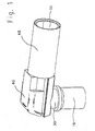
- the first and the second metal sleeve at right angles to each other are arranged, that is, a right-angled coaxial connector is formed.
- a right-angled coaxial connector is shown, the first Has receiving chamber 10 and a second receiving chamber 12. This are made of a first metal sleeve 14 and a second metal sleeve 16 enclosed.
- the first metal sleeve 14 is formed from a first half-shell 18 and one second half shell 20.
- the first half shell is in its with respect to the figures left half executed with a slightly reduced width, while the second half shell 20 is carried out continuously with the same width, namely with the width of the right half of the first half-shell 18.
- the second half-shell 20 is provided on its left half with two aprons 22, which with the in the The width of the reduced area of the first half-shell 18 overlap.
- the right half of the figures are the first half-shell 18 and the second ' Half shell 20 butt against one another, so that the cylindrical receiving space 10 is formed.
- the first half-shell 18 is at its left end with respect to the figures a recess 24 into which a retaining tab 26 on the second Half shell 20 engages.
- the recess 24 together with the retaining tab 26 forms a hinge between the two half-shells.
- the second metal sleeve 16 is inserted into the first half-shell 18 on its underside facing away from the second half-shell 20.
- the second metal sleeve 16 For fixing in the first half-shell 18 is the second metal sleeve 16 with a flanged Edge 28 provided.
- first plastic body 30 which is made of a dielectric material consists.
- the plastic body 30 is in the second metal sleeve 16 and the first Half-shell injected, both of which have small passage openings 32 are through which the first plastic body 30 to the outside of the extends second metal sleeve 16 and also the first half-shell 18.
- a receptacle 34 which is in the manner of a Stepped bore is executed and a receiving groove in the region of the half-shell 18 35 has.
- metallic inner conductor 36 In the receptacle 34 can be angled by 90 ° metallic inner conductor 36 are used, which has a locking collar 38. The end of the inner conductor pointing downward with respect to the figures is shown as Plug-in section and the end pointing to the right as crimp section 39 educated.
- a second plastic body 40 is injected into the second half-shell 20, which is also made of a dielectric material.
- the second too Plastic body 40 extends through small openings in the second half shell 20 to the outside. There are also grooves for one Strain relief provided.
- the first plastic body 30 and the second plastic body 40 are each provided with several grooves 42, which together provide a strain relief for a cable form. Furthermore, the first plastic body 30 has two projections 44 provided, which in complementary recesses 46 in the second plastic body 40th intervention.
- a crimp sleeve 48 is provided, which on the right half of the first half-shell 18 and the second half-shell 20 pushed on and there can be crimped.
- the coaxial connector described is produced in the following Way: First, the two half-shells 18, 20 are punched and deep-drawn. The second metal sleeve 16 is then inserted into the first half-shell 18 and flanged there. Then the first plastic body 30 into the second Metal sleeve 16 and the first half-shell 18 are injected, and the second Plastic body 40 is injected into the second half-shell 20.
- a cable can then be inserted into the crimp section 39 of the inner conductor 36 used and crimped there.
- Inner conductor 36 is then inserted into receptacle 34 in first plastic body 30 used that his locking collar 38 on the shoulder of the stepped bore of the receptacle 34 abuts and the crimp section lies in the receiving groove 35.
- the second half shell 20 is placed on the first half shell 18 by the Retaining tab 26 of the second half-shell 20 in the recess 24 of the first Half shell 18 is hooked.
- the second half shell 20 placed obliquely from above onto the first half-shell 18.
- the aprons 22 After hooking it in the second half shell 20 can be folded down onto the first half shell 18, the aprons 22 then with the left half of the first half shell 18 overlap and the recesses 46 of the second plastic body 40 over the Grip projections 44 of the first plastic body 30. In this way it is second half shell 20 in the longitudinal direction and in the transverse direction on the first Half shell 18 locked.
- the second plastic body is on the Crimp section 39 of the inner conductor 36 so that it is fixed in the receptacle 34 and the receiving groove 35 is locked.
- the grooves 42 engage Hold the plastic body on the cable attached in the crimp section 39 and hold it there it firmly so that a strain relief is formed.
- the crimp sleeve 48 is on the right half of the first Half-shell 18 and the second half-shell 20 pushed on and crimped there.
- the crimp sleeve 48 ensures that the second half-shell 20 in the area of their right half can no longer be lifted from the first half-shell 18; in the area of the left half this is ensured by the retaining tab 26 and the Recess 24 formed hinge that the two half-shells firmly together are connected.
- both the strain relief is over by the crimping the dielectric plastic body as well as a safe shield transmission a braid of the cable on the metal sleeve 14 ensured.
- the coaxial connector formed in this way has a particularly good RF shielding on.
- the second metal sleeve 16 is closed all around, so that Complete shielding is guaranteed here.
- the small openings 32 do not affect the RF shielding because of their diameter is smaller than the wavelength of the HF radiation.
- In the area of the first and the second half-shell 18, 20 also results in perfect RF shielding.
- the crimp sleeve 48 which is completely closed, ensures the good one Shielding.
- the coaxial connector can be plugged in Manufacture and assemble in a particularly simple manner, since there are few, easily automated Assembly steps are necessary.
Landscapes
- Coupling Device And Connection With Printed Circuit (AREA)
Applications Claiming Priority (2)
| Application Number | Priority Date | Filing Date | Title |
|---|---|---|---|
| DE10232662 | 2002-07-18 | ||
| DE10232662A DE10232662A1 (de) | 2002-07-18 | 2002-07-18 | Abgewinkelter Koaxialstecker |
Publications (1)
| Publication Number | Publication Date |
|---|---|
| EP1383209A1 true EP1383209A1 (fr) | 2004-01-21 |
Family
ID=29762047
Family Applications (1)
| Application Number | Title | Priority Date | Filing Date |
|---|---|---|---|
| EP03013484A Withdrawn EP1383209A1 (fr) | 2002-07-18 | 2003-06-26 | Connecteur coaxial angulaire |
Country Status (4)
| Country | Link |
|---|---|
| US (1) | US20040014358A1 (fr) |
| EP (1) | EP1383209A1 (fr) |
| JP (1) | JP2004055552A (fr) |
| DE (1) | DE10232662A1 (fr) |
Cited By (3)
| Publication number | Priority date | Publication date | Assignee | Title |
|---|---|---|---|---|
| EP1732172A1 (fr) * | 2005-06-06 | 2006-12-13 | John MezzaLingua Associates, Inc. | Connecteur coaxial avec isolateur dirigeant |
| EP2833483A1 (fr) * | 2013-08-02 | 2015-02-04 | Coninvers GmbH | Connecteur à fiche électrique à angle arrondi doté de deux pièces de coque de boîtier |
| US20220043230A1 (en) * | 2020-08-07 | 2022-02-10 | Neutrik Ag | Plug connector part for an optical and/or electrical plug connection |
Families Citing this family (10)
| Publication number | Priority date | Publication date | Assignee | Title |
|---|---|---|---|---|
| CN2800594Y (zh) * | 2005-05-10 | 2006-07-26 | 富士康(昆山)电脑接插件有限公司 | 电源连接器 |
| DE102006012337B3 (de) | 2006-03-17 | 2007-11-29 | Amphenol-Tuchel Electronics Gmbh | Elektrischer Steckverbinder |
| DE102007013216B3 (de) * | 2007-03-15 | 2008-06-19 | Schäfer Werkzeug- und Sondermaschinenbau GmbH | Tiefgezogenes Steckergehäuse für elektrische Geräte |
| DE102008054585B4 (de) | 2008-12-12 | 2010-11-11 | Lisa Dräxlmaier GmbH | Winkelsteckverbindung für geschirmte Kabel |
| JP5489691B2 (ja) * | 2009-12-16 | 2014-05-14 | 矢崎総業株式会社 | L字型端子の絶縁構造 |
| FR2986378B1 (fr) * | 2012-01-26 | 2014-11-28 | Radiall Sa | Ensemble et element de connexion hyperfrequence et procede de fabrication d'un tel element |
| DE102012201123B3 (de) * | 2012-01-26 | 2013-03-21 | Lisa Dräxlmaier GmbH | Gewinkelter Hochvolt-Stecker |
| US9825395B2 (en) * | 2015-05-14 | 2017-11-21 | Te Connectivity Corporation | Protective cover for a connector |
| DE102018118405B3 (de) * | 2018-07-30 | 2019-12-05 | Ims Connector Systems Gmbh | Steckverbinder sowie Steckverbindung mit einem solchen Steckverbinder |
| DE102020117663A1 (de) | 2020-07-03 | 2022-01-05 | Rosenberger Hochfrequenztechnik Gmbh & Co. Kg | Außenleiterkontaktelement, Winkelsteckverbinder und Verfahren zur Herstellung eines Winkelsteckverbinders |
Citations (6)
| Publication number | Priority date | Publication date | Assignee | Title |
|---|---|---|---|---|
| US4173386A (en) * | 1978-03-13 | 1979-11-06 | W. L. Gore & Associates, Inc. | Coaxial assembly |
| US4799900A (en) * | 1987-10-15 | 1989-01-24 | Amp Incorporated | Push on right angle connector |
| US4892491A (en) * | 1988-12-19 | 1990-01-09 | Motorola, Inc. | Coaxial connector |
| US5030122A (en) * | 1989-04-20 | 1991-07-09 | Amp Incorporated | Self terminating connector and cable assembly |
| US6217381B1 (en) * | 1998-11-17 | 2001-04-17 | Yazaki Corporation | Connector for a coaxial cable and its connecting method |
| EP1191642A2 (fr) * | 2000-09-26 | 2002-03-27 | Itt Manufacturing Enterprises, Inc. | Connecteur du type coaxial |
Family Cites Families (8)
| Publication number | Priority date | Publication date | Assignee | Title |
|---|---|---|---|---|
| US2813144A (en) * | 1950-12-20 | 1957-11-12 | Amphenol Electronics Corp | Coaxial angle connector |
| US2952823A (en) * | 1956-03-26 | 1960-09-13 | Boeing Co | High-frequency coaxial transmission line elbow fittings |
| US4655534A (en) * | 1985-03-15 | 1987-04-07 | E. F. Johnson Company | Right angle coaxial connector |
| US4775329A (en) * | 1987-06-18 | 1988-10-04 | E. I. Du Pont De Nemours And Company | Branch connector for coaxial cable |
| GB9019540D0 (en) * | 1990-09-07 | 1990-10-24 | Amp Great Britain | Coaxial electrical connectors and their manufacture |
| US5037329A (en) * | 1990-09-27 | 1991-08-06 | Gte Products Corporation | Angular connector for a shielded coaxial cable |
| US5362255A (en) * | 1993-09-14 | 1994-11-08 | Itt Corporation | Coaxial connector |
| DE10146329B4 (de) * | 2001-09-20 | 2009-02-26 | Neutrik Aktiengesellschaft | Elektrischer Kabelstecker |
-
2002
- 2002-07-18 DE DE10232662A patent/DE10232662A1/de not_active Withdrawn
-
2003
- 2003-06-26 EP EP03013484A patent/EP1383209A1/fr not_active Withdrawn
- 2003-07-15 US US10/620,264 patent/US20040014358A1/en not_active Abandoned
- 2003-07-16 JP JP2003197945A patent/JP2004055552A/ja not_active Abandoned
Patent Citations (6)
| Publication number | Priority date | Publication date | Assignee | Title |
|---|---|---|---|---|
| US4173386A (en) * | 1978-03-13 | 1979-11-06 | W. L. Gore & Associates, Inc. | Coaxial assembly |
| US4799900A (en) * | 1987-10-15 | 1989-01-24 | Amp Incorporated | Push on right angle connector |
| US4892491A (en) * | 1988-12-19 | 1990-01-09 | Motorola, Inc. | Coaxial connector |
| US5030122A (en) * | 1989-04-20 | 1991-07-09 | Amp Incorporated | Self terminating connector and cable assembly |
| US6217381B1 (en) * | 1998-11-17 | 2001-04-17 | Yazaki Corporation | Connector for a coaxial cable and its connecting method |
| EP1191642A2 (fr) * | 2000-09-26 | 2002-03-27 | Itt Manufacturing Enterprises, Inc. | Connecteur du type coaxial |
Cited By (5)
| Publication number | Priority date | Publication date | Assignee | Title |
|---|---|---|---|---|
| EP1732172A1 (fr) * | 2005-06-06 | 2006-12-13 | John MezzaLingua Associates, Inc. | Connecteur coaxial avec isolateur dirigeant |
| US7270569B2 (en) | 2005-06-06 | 2007-09-18 | John Mezzalingua Associates, Inc. | Coax connector having steering insulator |
| CN100546123C (zh) * | 2005-06-06 | 2009-09-30 | 约翰·梅扎林瓜联合公司 | 配备转向绝缘体的同轴连接器 |
| EP2833483A1 (fr) * | 2013-08-02 | 2015-02-04 | Coninvers GmbH | Connecteur à fiche électrique à angle arrondi doté de deux pièces de coque de boîtier |
| US20220043230A1 (en) * | 2020-08-07 | 2022-02-10 | Neutrik Ag | Plug connector part for an optical and/or electrical plug connection |
Also Published As
| Publication number | Publication date |
|---|---|
| US20040014358A1 (en) | 2004-01-22 |
| DE10232662A1 (de) | 2004-01-29 |
| JP2004055552A (ja) | 2004-02-19 |
Similar Documents
| Publication | Publication Date | Title |
|---|---|---|
| DE69923410T2 (de) | Abschirmende Anschlußklemme | |
| DE602005005100T2 (de) | Wasserdichter Verbinder und sein Zusammenbauverfahren | |
| DE60035383T2 (de) | Eine abgeschirmte Anschlussklemme und ein Verfahren für die Verbindung einer abgeschirmten Anschlussklemme | |
| DE2446857C2 (de) | Elektrische Steckverbindungsanordnung | |
| DE102015004485B4 (de) | Verfahren zum Herstellen einer Steckverbinderanordnung | |
| DE3823617C2 (fr) | ||
| DE1465204A1 (de) | Kupplung fuer abgeschirmte Mehrleiter-Kabel | |
| DE69836792T2 (de) | Kupplungsvorrichtung für ein Ende eines Koaxialkabels | |
| DE112018000682T5 (de) | Abschirmanschluss | |
| DE102005041294A1 (de) | Verbinder und Verfahren zum Zusammenbauen desselben | |
| DE2652250B2 (de) | Elektrische Kontaktvorrichtung | |
| EP1133013B1 (fr) | Pièce de contact pour une connexion électrique ainsi que son procédé de fabrication | |
| DE112018000673T5 (de) | Abschirmanschluss | |
| EP1383209A1 (fr) | Connecteur coaxial angulaire | |
| DE3735205A1 (de) | Mehrpolige steckbare kupplungshaelfte fuer elektrische leitungen | |
| EP0009493B1 (fr) | Connecteur éléctrique et procédé de fabrication | |
| DE3133154A1 (de) | Koaxial-abgriffverbinder | |
| DE102015003935B3 (de) | Verbinder, Verfahren und Verwendung | |
| DE19844695A1 (de) | Koaxialverbinder, Koaxialverbinderanordnung und Verfahren zu deren Herstellung | |
| DE19727265C2 (de) | Steckanschluß-Preßsitzkonstruktion | |
| DE3410461A1 (de) | Steckerbuchse mit isolierstoffummantelung sowie vorrichtung fuer ihre herstellung | |
| DE2844786A1 (de) | Einstueckiger, ummantelter kontakt | |
| DE3643087A1 (de) | Schnellkupplungsklemme fuer den klemmenpol eines elektrischen geraetes | |
| DE1615823B2 (de) | Elektrische Steckvorrichtung mit einem Steck- und einem Dosenteil | |
| DE19548168A1 (de) | Einteiliges Kontaktelement |
Legal Events
| Date | Code | Title | Description |
|---|---|---|---|
| PUAI | Public reference made under article 153(3) epc to a published international application that has entered the european phase |
Free format text: ORIGINAL CODE: 0009012 |
|
| AK | Designated contracting states |
Kind code of ref document: A1 Designated state(s): AT BE BG CH CY CZ DE DK EE ES FI FR GB GR HU IE IT LI LU MC NL PT RO SE SI SK TR |
|
| AX | Request for extension of the european patent |
Extension state: AL LT LV MK |
|
| 17P | Request for examination filed |
Effective date: 20040514 |
|
| 17Q | First examination report despatched |
Effective date: 20040618 |
|
| AKX | Designation fees paid |
Designated state(s): AT BE BG CH CY CZ DE DK EE ES FI FR GB GR HU IE IT LI LU MC NL PT RO SE SI SK TR |
|
| STAA | Information on the status of an ep patent application or granted ep patent |
Free format text: STATUS: THE APPLICATION IS DEEMED TO BE WITHDRAWN |
|
| 18D | Application deemed to be withdrawn |
Effective date: 20050721 |